Eizo DuraVision DX0211-IP Installation Manual
Ip decoding box
Hide thumbs
Also See for DuraVision DX0211-IP:
- Instruction manual (52 pages) ,
- Technical brief (12 pages) ,
- Instruction manual (18 pages)
Table of Contents
Advertisement
Quick Links
Installation Manual
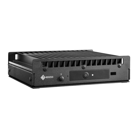
IP Decoding Box
Software Version 5.2
Important
Please read this "Installation Manual", "Instruction Manual", and
"Setup Manual" carefully to familiarize yourself with safe and effective
usage.
• For the latest product information including the "Installation Manual",
refer to our web site :
www.eizoglobal.com
Advertisement
Table of Contents

Subscribe to Our Youtube Channel
Related Manuals for Eizo DuraVision DX0211-IP


Summary of Contents for Eizo DuraVision DX0211-IP
- Page 1 Installation Manual IP Decoding Box Software Version 5.2 Important Please read this “Installation Manual”, “Instruction Manual”, and “Setup Manual” carefully to familiarize yourself with safe and effective usage. • For the latest product information including the “Installation Manual”, refer to our web site : www.eizoglobal.com...
- Page 2 EIZO Corporation is under no obligation to hold any submitted material or information confidential unless prior arrangements are made pursuant to EIZO Corporation’s receipt of said information. Although every effort has been made to ensure that this manual provides up-to-date information, please note that EIZO monitor specifications are subject to change without notice.
-
Page 3: Table Of Contents
CONTENTS CONTENTS ............. 3 Chapter 5 Live Image Screen Settings ... 49 Chapter 1 Product Overview ......4 5-1. Setting Display Positions of Camera Video Images ..........49 1-1. Features ............4 5-2. Setting Display Methods of Camera 1-2. System Configuration ........5 Video Images ..........51 1-3. -
Page 4: Chapter 1 Product Overview
Utilizes SSL and TLS, which are secure protocols. Communication between network cameras and web pages is encrypted using SSL and HTTPS. Purchase an Enterprise License to use LDAP authentication. For details, contact your dealer or local EIZO representative. Chapter 1 Product Overview... -
Page 5: System Configuration
● Support • A 2-year long-term warranty for 24-hour continuous use ● Operation • Operations can be performed by using a keyboard or mouse 1-2. System Configuration This system can communicate with network cameras, display video on the monitor that is connected to this product, and operate the network cameras. -
Page 6: Supported Network Cameras
1-3. Supported Network Cameras This product supports ONVIF Profile S network cameras. Attention • Supported network cameras vary depending on the product's software version. Check the software version of the product you are using, then check our website (www.eizoglobal.com) for details on supported network cameras. For information on how to check the software version, refer to “2-2. -
Page 7: Chapter 2 Before Configuration
Chapter 2 Before Configuration System settings can be made from the screen (application screen) displayed on the monitor connected to the product or from the web browser of a computer connected to the same network. 2-1. Logging In to the System To configure this product, you need to log in to the system. - Page 8 Select (Login) under “System”. The login screen is displayed. Enter “Username : ” and “Password : ”. Select “Login”. The display returns to the live image screen. Select (Settings). The setting screen is displayed. Chapter 2 Before Configuration...
-
Page 9: Configuring From A Web Browser
Entering characters • When entering using a USB keyboard Typed characters are entered in the text box. • When entering using a USB mouse Clicking an item that requires characters to be input, such as a text box, will display a software keyboard. When the focus is moved out of the software keyboard, the software keyboard is hidden. -
Page 10: Setting Screen
2-2. Setting Screen The setting screen is comprised of “Basic Information”, “System Settings”, and “Live Image Screen Settings”. ● Basic Information Information on various settings of this product is displayed in a list. Clicking on an item tab at the top of the screen will display each setting item. System Information Displays the current status. -
Page 11: Chapter 3 System Settings
Chapter 3 System Settings Perform settings for the date and time of the system, network settings, and maintenance. These operations can be performed from the application screen or from the web browser. This chapter explains the procedure using the web browser. However, except for a few functions, the same functions can be used with either method. - Page 12 Set the following items. Network Settings Item Detail Setting range IP Setting Method Select “IP Setting Method”. DHCP / Manual IP Address When “Manual” is selected under “IP Setting Method”, “IP 0.0.0.0 to Subnet Mask Address”, “Subnet Mask”, and “Gateway” can be set. 255.255.255.255 Gateway Attention...
-
Page 13: Performing Communication Settings
3-2. Performing Communication Settings The communication settings are used to configure the web interface function and detection of communication errors. Select “Communication” of “System”. The “Communication” screen is displayed. Set the following items. Item Detail Setting range Comm. Error Detection Set the message display timing when the reception of video On / Off image data stops. - Page 14 Select “Apply”. The setting complete screen is displayed. Select “OK”. Attention • When “Web Interface” is set to “Off”, the settings cannot be configured from the web browser. • When “Web Interface” is set to “Off” and “Apply” is selected, the following warning message is displayed. Chapter 3 System Settings...
-
Page 15: Setting The Current Date And Time
3-3. Setting the Current Date and Time Attention • Set the correct dates. Incorrect dates may result in failure of secure communication during certificate validation. If you use SSL for communication with the camera or LDAP setting, avoid the state of power turned off for a long time of period or make sure correct time is set using NTP. - Page 16 Select “Apply”. The setting complete screen is displayed. Select “OK”. Note • When “Synchronize with PC” is selected for “Procedure”, the current date and time information of the computer is transmitted to this product. • If the system is not connected to the power supply for one week or longer, the date and time displayed on this product will become incorrect.
-
Page 17: Other System Settings
3-4. Other System Settings Perform the following settings: “Language”, “Resolution”, “Multi-Monitor”, “Key Lock”, “USB Lock”, “Remote Controller Lock”, “Power Indicator”, and “Keyboard Layout”. Select “Other” under “System”. The “Other” screen is displayed. Set the following items. Item Detail Setting range Language Set the display language of the menu and the setting 日本語... -
Page 18: Initializing The System
3-5. Initializing the System All settings are returned to default except for system logs, operation logs, the current time, time zone settings, license activation information, and the software version. Select “Maintenance” of “System”. The “Maintenance” screen is displayed. Select “Start” under “Factory Reset”. A confirmation message is displayed. -
Page 19: Restarting The System
3-6. Restarting the System Select “Maintenance” of “System”. The “Maintenance” screen is displayed. Select “Start” under “Restart”. A confirmation message is displayed. Select “OK”. The system will restart. Chapter 3 System Settings... -
Page 20: Updating Software
3-7. Updating Software The software version can be upgraded. Download the upgrade file from the EIZO website (www. eizoglobal.com) ahead of time. Attention • This function can be used only when using the web browser. Select “Maintenance” of “System”. The “Maintenance” screen is displayed. - Page 21 Select “OK”. A “Software is being updated” message is displayed. Select “OK”. Note • It takes approximately five minutes to update the software. • The red LED blinks while the software is updating. Chapter 3 System Settings...
-
Page 22: Saving Settings Data
3-8. Saving Settings Data Settings data can be exported to a file. The exported file can be used to transfer settings data. Attention • This function can be used only when using the web browser. Select “Maintenance” of “System”. The “Maintenance” screen is displayed. Select “Save Settings Data”... -
Page 23: Loading System Settings Data
3-9. Loading System Settings Data Load settings data from a file. Attention • This function can be used only when using the web browser. Note • Regardless of the software version, it is possible to switch the LDAP settings. Select “Maintenance” under “System”. The “Maintenance”... - Page 24 Enter the password that was specified when saving the settings data in “Password”. Select the data to be loaded. Place a check mark in the check box. Select “Execute”. When loading is completed, a message is displayed. Select “OK”. Attention •...
-
Page 25: Performing License Activation
3-10. Performing License Activation The software edition can be changed. Usable functions are added for Enterprise Edition. For details, contact your dealer or local EIZO representative. Attention • This function can be used only when using the web browser. Select “Maintenance” of “System”. -
Page 26: Setting Event Rules
3-11. Setting Event Rules Actions to be executed when “Alert request received”, “Timer expired”, and “Video output status change” events occur can be set. Note • A total of 16 individual Event Rules can be set. Select “Event Rules” of “System”. The “Event Rules”... - Page 27 Set Event Rules. Item Detail Setting range Name Enter the name of the Event Rule. Alphanumeric, kana , and kanji (Up to 24 characters) Status Select whether to enable or disable the Event Rule. Active / Inactive Event Select an event to trigger an action. Alert request received / Timer The items that can be set differ depending on the event.
-
Page 28: Performing Certificate Settings
3-12. Performing Certificate Settings Select “Certificate” of “System”. The “Certificate” screen is displayed. Perform certificate settings. Server Certificate The Server Certificate is used when accessing this product from the web browser via HTTPS. Attention • A Certificate Signing Request (CSR) cannot be created with this product. •... - Page 29 Root Certificate The Root Certificate is used when performing an HTTPS connection with network cameras from this product, or when performing an LDAPS connection to the LDAP server. Attention • Root Certificate registration is only possible via web browser. • A Root Certificate is not pre-installed in this product. Select “Register”, and the select “Root Certificate”.
-
Page 30: Setting The Remote Control Id
3-13. Setting the Remote Control ID This function is for use with models equipped with a remote control. When using multiple units of this product, the product operated by a remote control can be limited by specifying the ID shared by the product and remote control. With the factory values, all products that receive the remote control signal will operate accordingly. -
Page 31: Setting The Remote Control Id
● Setting the remote control ID Press and hold for more than 3 seconds. With pressed, enter the ID (0 to 99) you want to set with the number buttons. Note • If the ID you want to set is a single digit number, enter 0 before it. (Ex: To set “3”, enter “03”.) Release Note... -
Page 32: Saving Logs
3-15. Saving Logs Save operation logs and system logs. Use these logs to check the current or past conditions of the system or to find out the cause when a problem occurs. Attention • This function can be used only when using the web browser. Select “Log Display”... -
Page 33: Performing Camera Connection Confirmation
3-16. Performing Camera Connection Confirmation The connection status of the network cameras can be confirmed. Attention • This function can be used only when using the web browser. Select “Connection Confirmation” of “Troubleshooting”. The “Connection Confirmation” screen is displayed. Select “Camera Name”. Select “Run”... -
Page 34: Confirming Network Connection Status
3-17. Confirming Network Connection Status Select “Network Connection Status” of “Troubleshooting”. The “Network Connection Status” screen is displayed. Select “Current Status”. The connection status is displayed in the lower area. Note • Select “Reconnect” to reset the network status. The connection status is not displayed. Chapter 3 System Settings... -
Page 35: Chapter 4 Management Of Network Cameras
Chapter 4 Management of Network Cameras This section describes the procedure for network camera registration and function settings, and to reflect them on the system. These operations can be performed from the application screen or from the web browser. This chapter explains the procedure using the web browser. However, except for a few functions, the same functions can be used with either method. - Page 36 Set each item and select “OK”. Item Detail Setting range Camera Name Enter the camera name. If “Obtain Camera Name” is Alphanumeric, selected, the camera name is automatically obtained from kana , and the network camera.* kanji (Up to 24 •...
- Page 37 *1 This can be obtained only when “IP Address”, “Port”, “Username”, and “Password” are input. *2 If “Protocol” is “DirectUri,” the “Obtain Camera Name” button is not displayed. *3 This can be input only when displayed on the web browser. *4 When “Protocol”...
-
Page 38: Changing Network Camera Information
4-2. Changing Network Camera Information Select “Camera Registration”. A screen is displayed to show a list of camera registration information. Select the position number of the camera to be changed. Place a check mark on the check box of the position number of the camera to be changed. Select “Manual Registration”. - Page 39 Select “Apply”. A confirmation message is displayed. Select “OK”. Note • If there is a failure in obtaining “Obtain Camera Name” or “Obtain Profile” information, the following message is displayed. Try obtaining the information again. Chapter 4 Management of Network Cameras...
-
Page 40: Auto Discovery Of Network Cameras
4-3. Auto Discovery of Network Cameras Network cameras installed on the same network as this product can be automatically detected and registered. Select “Camera Registration”. A screen is displayed to show a list of camera registration information. Select “Auto Discovery” in the lower part of the screen. Select “Protocol”. -
Page 41: Deleting Network Cameras
4-4. Deleting Network Cameras Select “Camera Registration”. A screen is displayed to show a list of camera registration information. Select the camera to be deleted. Place a check mark on the check box of the position number of the camera to be deleted. Select “Delete”... -
Page 42: Exporting Network Camera Information
4-5. Exporting Network Camera Information The list of camera registration information can be saved in a CSV file. The exported file can be used when transferring network camera information. Attention • This function can be used only when using the web browser. Select “Camera Registration”. -
Page 43: Importing Network Camera Information
4-6. Importing Network Camera Information A CSV file that contains additional camera candidates can be imported and used for registration. Attention • This function can be used only when using the web browser. Select “Camera Registration”. A screen is displayed to show a list of camera registration information. Select “Load Camera Information”. - Page 44 Select “Apply”. A setting confirmation dialog box is displayed. Select “OK”. Note • Up to 255 candidate cameras can be read. • The CSV files that can be read are as follows. - CSV files exported from the web browser - CSV files created by the user •...
-
Page 45: Setting Network Camera Time
4-7. Setting Network Camera Time Adjust the time of the network camera to the time of this product. Attention • Cannot be set if the camera does not support this function. • Can only be set when “Protocol” is “Panasonic” or “ONVIF” during camera registration. Select “Camera Function Settings”. -
Page 46: Setting Quality Of Transmission Video Images
4-8. Setting Quality of Transmission Video Images Set the quality of video images transmitted from the network cameras. Note • This product supports H.264, H.265 (Panasonic only), and MJPEG video compression formats. Attention • When devices such as recorders are connected to a network camera, the display and recording of such devices may be affected. - Page 47 Set the following items under “Video Settings”. Protocol Item Detail Setting range Panasonic AXIS ONVIF Media Profile Select the profile. EIZO_Profile / Profile √ of each camera Encoder Select the encoder settings. According to the √ camera specifications Compression Format Select the compression format. H.264 / H.265 / √...
- Page 48 Note • If “Protocol” of the network camera is set to “DirectUri”, setting contents are displayed. • The following settings are possible in “Other” when “Protocol” is “Panasonic” during camera registration. - Pan/Tilt-flip - Upside-down - Lamp Display Select “Apply”. The setting complete screen is displayed.
-
Page 49: Chapter 5 Live Image Screen Settings
Chapter 5 Live Image Screen Settings In the live image screen settings, display settings such as changing the live image screen layout are performed. 5-1. Setting Display Positions of Camera Video Images Set the display position for video images from the network camera. You can switch the display positions of the source and destination camera images by dragging and dropping the camera name. - Page 50 Select the layout of the live image screen. Select one from the “Layout” list box. Note • When a layout is selected, the display on the page changes to the selected state. You can set the layout while imagining the display status. •...
-
Page 51: Setting Display Methods Of Camera Video Images
5-2. Setting Display Methods of Camera Video Images Perform settings for whether to display or hide the camera name, specifying the screen switching interval, and aspect ratio. Select “Other Display Settings” of “Display”. The “Other Display Settings” screen is displayed. Set the following items. -
Page 52: Setting Custom Screen Layouts
5-3. Setting Custom Screen Layouts Set the display layout when “Custom Screen” is selected in “Layout” for the Live Image Screen. Select “Custom Scr. Settings” of “Display”. The “Custom Scr. Settings” screen is displayed. Note • Click in the display position frame to fix the display position of any camera image. The display position for the specified camera image is maintained even if the pages are switched. -
Page 53: Setting The Display Methods Of Live Image Screens
5-4. Setting the Display Methods of Live Image Screens Display settings such as changing the live image screen layout are performed. Select “Live Image Screen Settings” of “Live Image Screen”. The “Live Image Screen Settings” screen is displayed. Select each setting item from the list box. Item Detail Setting range... -
Page 54: Setting Current Monitor Display Status
5-5. Setting Current Monitor Display Status Select “System Status Settings” of “Live Image Screen”. The “System Status Settings” screen is displayed. Click ▼ next to “Current Status” to select the status from the displayed list. Item Detail Live Image Screen The monitor screen shows the Live Image Screen Quick Shutdown The power is off... -
Page 55: Chapter 6 Management Of The User Account
Chapter 6 Management of the User Account Perform procedures such as registering, changing, and deleting user accounts (username, user level, and password) used to access the system, and for configuring Auto Login settings. Attention • A maximum of ten persons can be registered for the user account. User information for a new user cannot be registered when there are already 10 users registered. - Page 56 Select “Add”. A dialog box for setting the user account is displayed. Set the user account. Item Description Username Enter a username. Enter the username with alphanumerics excluding “ : ”. User Level Select “LIVE”, “CAMERA CONTROL”, and “ADMIN”. The operable range of this product differs by each level. Password Specify the password.
-
Page 57: Changing The User Account
6-2. Changing the User Account Attention • This function cannot be used if “LDAP” is selected in “User Account”. For details, refer to “6-5. Performing LDAP Settings” (page 60). Select “Local User” of “User”. The “Local User” screen is displayed. Select a user to be changed from “User List”. -
Page 58: Deleting The User Account
6-3. Deleting the User Account Attention • This function cannot be used if “LDAP” is selected in “User Account”. For details, refer to “6-5. Performing LDAP Settings” (page 60). Select “Local User” of “User”. The “Local User” screen is displayed. Select a user to be deleted from “User List”. -
Page 59: Configuring Auto Login Settings
6-4. Configuring Auto Login Settings Attention • This function cannot be used if “LDAP” is selected in “User Account”. For details, refer to “6-5. Performing LDAP Settings” (page 60). • Once the Auto Login settings are configured, unauthorized operation becomes easy for a malicious third party. Restrict the configuration to the application in an environment where sufficient security is ensured. -
Page 60: Performing Ldap Settings
6-5. Performing LDAP Settings It is possible to log in to this product using a user account on the LDAP server when using direct service (LDAP) in User Management. Attention • This function can only be used when the software edition is “Enterprise”. For information on software editions, refer to “3-10. - Page 61 Perform LDAP settings. LDAP Item Detail Setting range Server Address Enter the IP address of the LDAP server. 0.0.0.0 to 255.255.255.255 Port Enter the port number. 1 to 65535 Base DN Enter the identification name of the branch to search. Alphanumerics and symbols Ex: ou=ldap,dc=example,dc=com (up to 255 characters)
-
Page 62: Chapter 7 Troubleshooting
Chapter 7 Troubleshooting 7-1. Imaging Problems Problem Possible cause and remedy 1. The screen is not displayed on the monitor • Check that the power supply to the monitor is turned • Is the HDMI cable correctly connected? Is the input signal on the monitor set to the HDMI input? 2. - Page 63 Problem Possible cause and remedy 5. An error message “E**-**” is displayed on the • When Communication failed (“E01-**”) camera image display area - A number of devices exceeding the allowable number of devices for simultaneous connection may be connected to the network camera. Disconnect other network devices accessing the camera or reduce the resolution of the camera.
-
Page 64: Setting Problems
7-2. Setting Problems Problem Possible cause and remedy 1. Cannot log in • Enter the user name and password again. • Reset the account information using the Reset button and log in as the default setting account. (See “Setup Manual”) 2. -
Page 65: List Of Functions
List of Functions Basic Information ..........................page 10 System Information Camera / Display Position Date and Time Network Communication Certificate Other Event Rules Remote Controller User Account System Settings Camera Registration Manual Registration ..................page 35 / page 38 Delete ...........................page 41 Save Camera Information ..................page 42 Load Camera Information... -
Page 66: Appendix
If the open source software contains a product for which usage us granted under a GPL (GNU GENERAL PUBLIC LICENSE) license, EIZO Corporation will, in line with the GPL usage license conditions, provide the source code for corresponding GPL software via a medium, such as CD-ROM, at a cost to individuals and organizations who make contact via the following contact information for a minimum period of three years after purchase of the product. - Page 67 03V27691C1 IM-DX0211-IP Copyright © 2019 - 2020 EIZO Corporation. All rights reserved. 3rd Edition-February, 2020...
Need help?
Do you have a question about the DuraVision DX0211-IP and is the answer not in the manual?
Questions and answers