HWH 2000 Series Operator's Manual
Computer-controlled leveling system
Hide thumbs
Also See for 2000 Series:
- Operator's manual (52 pages) ,
- Operator's manual (21 pages) ,
- Operator's manual (42 pages)
Table of Contents
Advertisement
Quick Links
OPERATOR'S MANUAL
HWH COMPUTER-CONTROLLED
2000 SERIES LEVELING SYSTEM
UNDERSTAND OPERATOR'S MANUAL BEFORE USING. BLOCK FRAME AND TIRES
Ph: 800/321-3494 (or) 563/724-3396 | Fax: 563/724-3408
AP37519
H H
W
CORPORATION
R
FEATURING:
Touch Panel Leveling Control
BI-AXIS Hydraulic Leveling
R
Straight-Acting Jacks
Multiple Room Extensions (with Air Seals)
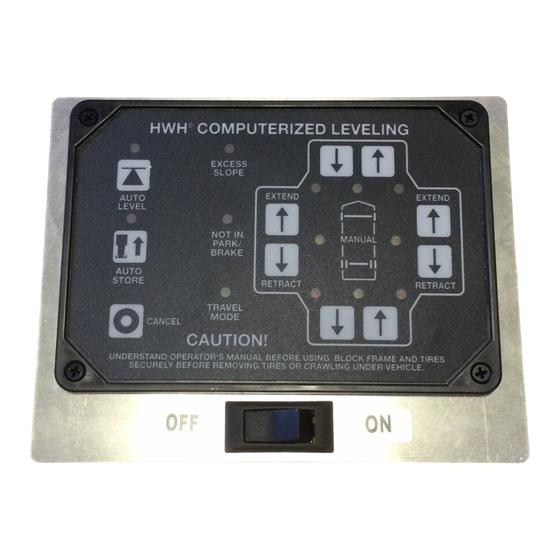
HWH COMPUTERIZED LEVELING
EXCESS
ON
SLOPE
LEVEL
NOT IN
PARK/
STORE
BRAKE
TRAVEL
MODE
OFF
CAUTION!
SECURELY BEFORE REMOVING TIRES OR CRAWLING UNDER VEHICLE.
HWH CORPORATION
(On I-80, Exit 267 South)
2096 Moscow Road | Moscow, Iowa 52760
www.hwh.com
R
ML37520/MP05.9991
12JUL06
Advertisement
Table of Contents

Related Manuals for HWH 2000 Series


Summary of Contents for HWH 2000 Series
- Page 1 CORPORATION OPERATOR’S MANUAL HWH COMPUTER-CONTROLLED 2000 SERIES LEVELING SYSTEM FEATURING: Touch Panel Leveling Control BI-AXIS Hydraulic Leveling Straight-Acting Jacks Multiple Room Extensions (with Air Seals) HWH COMPUTERIZED LEVELING EXCESS SLOPE LEVEL NOT IN PARK/ STORE BRAKE TRAVEL MODE CAUTION! UNDERSTAND OPERATOR’S MANUAL BEFORE USING. BLOCK FRAME AND TIRES SECURELY BEFORE REMOVING TIRES OR CRAWLING UNDER VEHICLE.
-
Page 2: How To Obtain Warranty Service
HWH CORPORATION personnel will contact you to the problem quickly. If the dealer has difficulty solving determine whether or not your claim is valid. If it is, HWH the problem, he should immediately contact the Customer CORPORATION will authorize repair or replacement of the Service Department, at HWH CORPORATION. -
Page 3: Control Identification
CONTROL IDENTIFICATION HARD RESET SWITCH (SEE HWH LIGHTED RESET SWITCH) "EXCESS SLOPE" MASTER WARNING LIGHT LEFT SIDE (RAISE) LIGHT (EXTEND) BUTTON "NOT IN PARK" LIGHT FRONT RETRACT (LOWER) BUTTON LEVELING SYSTEM FRONT EXTEND ACTIVE LIGHT HWH COMPUTERIZED LEVELING (RAISE) BUTTON... - Page 4 CONTROL IDENTIFICATION ROOM EXTENSION OPERATOR’S PANEL PUMP ON INDICATOR READY TO OPERATE LIGHT (RED) LIGHT (AMBER) CORPORATION HYDRAULIC ROOM EXTENSION EXTEND ROOM CONTROL KEY SWITCH SWITCH CAUTION! UNDERSTAND OPERATOR’S MANUAL BEFORE USING. KEEP PEOPLE AND OBSTRUCTIONS RETRACT CLEAR OF ROOM WHEN OPERATING. CONTROL FUNCTIONS KEY SWITCH: The KEY SWITCH controls power to the ROOM...
-
Page 5: Pump Run Time
For cold weather information see "COLD WEATHER OPERATIONS" below. The HWH systems with a computer processor monitor the pump run time and will turn the pump off if the run time exceeds a specified time. This time can vary with different systems. Due to available electronics or system design, the pump run time programs will also vary. -
Page 6: General Instructions
The HWH lighted reset switch is located on the vehicle A network problem with one room will not inhibit the use of overhead panel. If there is a failure at any time in the HWH the other rooms or leveling system after the reset switch is CAN network, the network will shut down. - Page 7 OPERATING PROCEDURES PREPARATION FOR TRAVEL Before traveling the red jack warning lights must be off and If the jacks and room extension are fully retracted but a red the "TRAVEL MODE" light must be on. If lights are not correct WARNING light is lit or the green "TRAVEL MODE"...
- Page 8 DO NOT FORCE THE ROOM. DO NOT REVERSE DIRECTION OF THE ROOM. BINDING OF ROOM CAN NOTE: Make sure there is adequate clearance to fully CAUSE ROOM DAMAGE. CONTACT HWH CORPORATION extend the room and that all storage doors are closed. CUSTOMER SERVICE FOR ASSISTANCE.
- Page 9 DIRECTION OF THE ROOM. BINDING OF ROOM CAN The air seal will deflate. The READY TO OPERATE light CAUSE ROOM DAMAGE. CONTACT HWH CORPORATION will flash. When the amber light is on steady the room can CUSTOMER SERVICE FOR ASSISTANCE.
- Page 10 OPERATING PROCEDURES JACK RETRACTION EXTENDED POSITION STORE/TRAVEL POSITION JACK POSITIONS CAUTION: CAUTION: THE OPERATOR MUST BE SURE THAT DO NOT RELY SOLELY UPON THE THERE ARE NO OBJECTS UNDER THE VEHICLE AND WARNING LIGHTS. IT IS THE OPERATOR’S THAT ALL PEOPLE ARE CLEAR OF THE VEHICLE. RESPONSIBILITY TO CHECK THAT ALL JACKS ARE IN THE STORE/TRAVEL POSITION BEFORE TRAVELING.
- Page 11 OPERATING PROCEDURES MANUAL JACK RETRACTION (4 Jack Systems with Valve Release Nuts) NOTE: Use the Valve Release Nuts for retracting only if NOTE: Prior to APRIL 2002 a 1/4" Nut Driver was sent the "STORE" button on the control panel will not retract with the Operators Manual.
-
Page 12: Maintenance
Dexron automatic transmission fluid contains red dye and can cause staining should a leak occur. DO NOT USE All jacks and any HWH room extension cylinders should be brake fluid or hydraulic jack fluid. Use of these can damage completely retracted before checking the oil level. The oil seals. - Page 13 Move the adjustment for that light very, very, slightly in qualified RV repair center, your vehicle or coach the OPPOSITE direction that is given in the above manufacturer, or HWH CORPORATION for service or repair. instructions for LED’s A, B, C, and D. This will allow MP45.3259 07MAY09 MP44.1501...
- Page 14 BREATHER CAP - DIPSTICK - 1/4" NUT DRIVER 1 1/2" DIAMETER VALVE RELEASE SOLENOID VALVE NOTE: DO NOT turn the valve release nut more than 4 and 1/2 (four and one half) turns counter clockwise. Damage to the valve may result. VALVE RELEASE PLASTIC PLUG 2 1/4"...
Need help?
Do you have a question about the 2000 Series and is the answer not in the manual?
Questions and answers