Table of Contents
Advertisement
Quick Links
AUDIO- & ALARMMANAGEMENT
PSS-224 C
PEU-056B
PMS-024
PCM-100B
PIC-208B
PRC-008B/108A/408A
COMPLIANT TO:
VDE-0833-4 / VDE 0828 / EN 60849
IEC 60849
OPERATING INSTRUCTIONS / BEDIENUNGSANLEITUNG
3000
PRM-108/208A
PEM-008A
PZM-310
PBA-/PWS-/PAS-300A
PSB-025/PRB-025
PCF-008
PSU-048/24 – 240/24
Config-Software
- ENGLISH
- DEUTSCH
Advertisement
Table of Contents

Related Manuals for RCS AUDIO-SYSTEMS VARES 3000


Summary of Contents for RCS AUDIO-SYSTEMS VARES 3000
- Page 1 3000 AUDIO- & ALARMMANAGEMENT PSS-224 C PRM-108/208A PEU-056B PEM-008A PMS-024 PZM-310 PCM-100B PBA-/PWS-/PAS-300A PIC-208B PSB-025/PRB-025 PRC-008B/108A/408A PCF-008 PSU-048/24 – 240/24 Config-Software COMPLIANT TO: VDE-0833-4 / VDE 0828 / EN 60849 IEC 60849 - ENGLISH OPERATING INSTRUCTIONS / BEDIENUNGSANLEITUNG - DEUTSCH...
- Page 2 SAFETY INSTRUCTIONS CAUTION / ACHTUNG Caution: to reduCe the risk of eleCtriC shoCk do not remove Cover (or BaCk) no user-serviCeaBle parts inside refer ser- viCiing to qualified personnel. aChtung: Zur vermeidung von stromsChlägen gehäuseaB- deCkung oder rüCkseite niCht entfernen. keine vom Benut- Zer Wartenden teile im inneren.
-
Page 3: Table Of Contents
INDEX / INTRODUCTION CONTENTS / INHALT SYSTEM-FEATURES / SYSTEM MERKMALE ............SYSTEM OVERVIEW / SYSTEM-ÜBERSICHT . - Page 4 FEATURES Advantages Die Vorteile of voice alarming systems von Sprachalarmierung Lifesaving in the case of an emergency! Lebensrettend im Notfall! In the case of an alarm, an electroacoustic emer- Ein elektroakustisches Notfallwarnsystem kann gency warning system may avoid panic by un- im Al armierungsfall durch verständliche Laut- derstandable speaker announcements, which sprech er durch sagen Panik vermeiden, wodurch...
- Page 5 SYSTEM OVERVIEW The Control-Center: PSS-224 C Die Steuerzentrale: VARES-3000 PSS-224 C CONTROL-CENTER System-components regarding usage as System-components regarding usage as »DIGITAL CALL SYSTEM« »VOICE ALARMING SYSTEM« COMPLIANT TO DIN EN 60849 / IEC 60849 System-Komponenten bei Lösung als System-Komponenten bei Lösung als »DIGITALES RUFSYSTEM« »SPRACHALARMIERUNGS-SYSTEM« GEMÄSS VDE 0833-4 / VDE 0828 / EN 60849 PSS-224 C PSS-224 C CONTROL-CENTER CONTROL-CENTER...
- Page 6 PSS-244B CONTROL-CENTER MODEL NO.: PSS-224C VARES-3000 Control-Center RCS AUDIO-SYSTEMS GMBH REAR VIEW PSS-224 C RÜCKANSICHT 1. Empty Slots 1. Leerschächte 7 empty slots for mounting the relay cards PRC-008 A, Leerschächte zum Einbau von Relaiskarten PRC-008x, PRC-108 A or PRC-408 A.
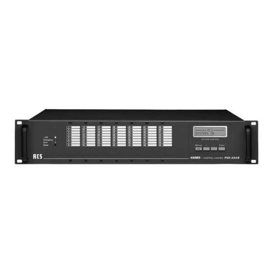
- Page 7 PSS-224 C CONTROL-CENTER MODEL NO.: PSS-224C RES-3000 Control-Center S AUDIO-SYSTEMS GMBH 1 2 3 4 7 8 9 BELEGUNG DER ANSCHLUSSSTECKER BUS CONNECTOR PINNING WITH BUS ASSIGNMENT MIT BUSBELEGUNG 1. PSU 1. PSU Anschluss für +24V Versorgungsspannung vom Schalt- Connector for +24V supply voltage from the switching netzteil (PSU-xxx/24) power supply (PSU-xxx/24) 2.
- Page 8 PSS-244B CONTROL-CENTER SETTING IN OPERATION INBETRIEBNAHME The basic device is delivered without any modules or relay- Das Grundgerät wird ohne Module oder Relaiskarten gelie- cards. In order to insert the different types of relay-cards or fert. Zum Einbau von ver-schiedenen Arten von Relaiskarten additional modules such as the chime-module, the cabinet oder Zusatzmodulen wie z.
- Page 9 PSS-224 C CONTROL-CENTER FRONTPANEL DISPLAYS DIE ANZEIGEN AN DER FRONTSEITE On the left side three LED’s can be spotted. The green LED An der linken Seite findet man drei Leuchtdioden. Die grüne indicates whether the main power is working. The red emer- LED zeigt an, ob die 24V Versorgungsspannung vorhanden gency LED lights up, when the main alarm is activated.
-
Page 10: Peu-056B
PEU-056B EXTENSION UNIT REARVIEW PEU-056B RÜCKANSICHT PEU-056B 1. Empty slot 1. Leerschächte These are empty slots to build in further relay cards, i.e. Leerschächte zum Einbau von Relaiskarten PRC-008x, PRC-008x, PRC-108x, PRC-408x or PRC-508x PRC-108x, PRC-408x oder PRC-508x. 2. Extension connector 2. Erweiterungsanschluss The ribbon cable PFK-200 is to be inserted into this jack In diese Buchse wird das Flachbandkabel PFK-200 ein- in order to connect up to three extension units PEU-056B gesteckt, um die bis zu drei Erweiterungsgeräte PEU-... -
Page 11: Pps-024B
PPS-024B PROGRAM SELECTOR FUNCTIONAL DESCRIPTION FUNKTIONSBESCHREIBUNG PPS-024B 24 differently programmed background-music zones may Mit dem PPS-024B lassen sich 24 verschieden program- be switched on and off manually with the PPS-024B. Each mierte Hintergrundmusikzonen von Hand ein- oder aus- relay can be allocated individually to one button on the PPS- schalten. Dabei kann jedem Relais eine Taste der PPS-024B 024B. -
Page 12: Phm-802A
PHM-802A AMPLIFIER MONITORING OPERATING ELEMENTS BEDIENELEMENTE PHM-802A 1. Control Key 1. Funktionstasten When pressing this key, you can operate through the dis- Durch Drücken dieser Tasten bewegen Sie sich durch play-menu. das Display-Menü. 2. Display 2. Anzeige The display shows the functions of the clock with its pre- Das Display zeigt die Funktionen der Verstärkerüberwa- programmed settings. - Page 13 PHM-802A AMPLIFIER MONITORING All devices connected to the BUS are to be regarded as angeschlossenen Geräte sind als gleichwertig zu betrachten equal and therefore can be wired in random order. The PSS- und können daher in beliebiger Reihenfolge verdrahtet wer- 224 C may also be located in the center of the remote micro- den. Das PHM-802x kann also auch in der Mitte zwischen phones.
- Page 14 PHM-802A AMPLIFIER MONITORING 10. Das Drücken der MENUE-Taste beendet das Hauptme- nü, die Menü-LED erlischt und das PHM-802x befindet sich wieder im Ruhezustand. 11. Die Tastensperre wird wie folgt aktiviert: Tasten + und ENTER drücken und 5s lang halten – nach Signalton ist die Tastatur gesperrt, Schlüssel-Symbol im Display. WICHTIGE HINWEISE ZUR MANUELLEN BEDIENUNG: • Die direkte Bedienung des Gerätes ohne „ConfigV3000“...
- Page 15 PHM-802A AMPLIFIER MONITORING ÜBERWACHUNG DER FUNKTIONEN DES PHM-802X • Auftretende Fehler werden durch einen Beeper, das Fehlerrelais und die blinkende Displaybeleuchtung si- gnalisiert. • Sind alle aufgetretenen Fehler behoben, setzt das Gerät seine eigene Fehleranzeige automatisch zurück (Beeper aus, Fehlerrelais aus), die aufgetretenen Fehler bleiben aber solange im Gerät gespeichert, bis sie von der PSS- 224 C abgeholt werden oder das Gerät neu gestartet wird.
-
Page 16: Ptc-240B
PTC-240B MAIN CLOCK OPERATING ELEMENTS BEDIENELEMENTE 1. Control Key 1. Funktionstasten Pressing these keys help to move through the display- Durch Drücken dieser Tasten bewegen Sie sich durch menu. das Display-Menü. 2. Display 2. Anzeige The display shows the functions of the clock and the pro- Das Display zeigt die Funktionen der Uhr und Ihrer grammed events. - Page 17 PTC-240B MAIN CLOCK SETTING UP THE MAIN CLOCK EINRICHTUNG DER HAUPTUHR (WITH SLAVE CLOCK LINES (INITIAL SETUP) MIT 2 NEBENUHR-LINIEN (ERSTEINRICHTUNG) Requirement: all slave clocks of one line show the exact Voraussetzung: Alle Nebenuhren einer Linie zeigen die gleiche same time (e.g. 12:00 h)! Uhrzeit (z.B.
- Page 18 PTC-240B MAIN CLOCK OPERATING THE PTC-240 B BEDIENUNG DER PTC-240B EXAMPLE OF MANUALLY ADJUSTING THE SIDE CLOCKS AM BEISPIEL DES MANUELLEN NACHSTELLENS DER NEBENUHREN Operation o f the main clock on the device can be done with Die Bedienung der Hauptuhr direkt am Gerät erfolgt mit 4 4 buttons;...
- Page 19 PTC-240B MAIN CLOCK IMPORTANT ADVICE REGADING MANUAL OPERATION: WICHTIGE HINWEISE ZUR MANUELLEN BEDIENUNG: • Operation of the device without ConfigV3000 is a special • Die direkte Bedienung des Gerätes ohne „ConfigV3000“ operational state. Dependent upon the activated menu, stellt einen besonderen Betriebszustand dar. In Abhängig- some of the functions of the main clock are not going to keit vom gerade aktiven Menüpunkt werden bestimmte be carried out temporarily.
-
Page 20: Prr-077A
PRR-077A DCF-RECEIVER SETTING IN OPERATION INBETRIEBNAHME This module works independently. It syn- Das Modul arbeitet selbständig. Es synchro- chronizes its internal clock with the DCF-time nisiert seine interne Uhr mit der DCF-Zeit in Frankfurt and maintains this information. It aus Frankfurt und hält diese Information zur works passively, which means that a device Abholung bereit. - Page 21 PRR-077A DCF-RECEIVER DISPLAY LED ANZEIGE LED The red LED indicates the operational status of the DCF- Die rote LED zeigt den Betriebszustand des DCF-Moduls module as follows: wie folgt an: 1. Rotes Dauerlicht: 1. Continuous red light: • D CF-Modul hat Betriebsspannung, aber kein DCF- •...
-
Page 22: Ptc-008B/108B
PTC-008B/108B RELEAY CARD SETTING IN OPERATION INBETRIEBNAHME The order of assembly of the Bestückungsreihenfolge relay cards has to be in ascen- der Relaiskarten ist zwingend ding order starting from “1” on aufsteigend mit „1“ beginnend, the front from left to right! On the frontseitig von links nach rechts back-side all of the slots are numbered as well. The exact einzuhalten. -
Page 23: Plc-400A
PLC-400A DISPLAY- & BUTTON MODULE SETTING IN OPERATION INBETRIEBNAHME The PLC-400x displays all system Das PLC-400x ermöglicht das information such as system-time, Anzeigen von Systeminformati- RCS VARES‐3000 errors, etc. Using the 4 buttons onen wie z.B. System-zeit, Feh- SYSTEM: OK you may maneuver through the lern, usw. Mittels der 4 Tasten system-menu. - Page 24 PRC-SERIES RELAY CARD PRC-008C/308B PRC-408A SETTING IN OPERATION INBETRIEBNAHME The relay cards mounting order must be followed precisely. Die Bestückungsreihenfolge der Relaiskarten ist zwingend You have to start with position 1 on the front panel from the aufsteigend mit „1“ beginnend, frontseitig von links nach left to the right side. On the rear panel the mounting positions rechts einzuhalten.
- Page 25 PRC-SERIES RELAY CARD 11. Fix it with the enclosed blind cover for cards and the 11. Mit der beiliegenden Kartenblende und den Linsenkopf- rounded head screw M3x6. schrauben M3x6 befestigen. 12. Insert possibly earlier removed relay cards again. 12. Evtl. vorher entfernte darüberliegende Relaiskarten wie- der einsetzen. 13. Screw possibly removed front panel and handles back 13. Evtl. vorher entfernte Frontplatte und Bügelgriffe wieder anschrauben. 14. Close cabinet cover. 14. Gehäusedeckel schließen. In case you would like to mount multiple cards, it is ea- Wenn mehrere Karten montiert werden sollen, ist es sier to remove the front plate circuit card after removing einfacher, nach entfernter Frontplatte die Frontplatinen-...
-
Page 26: Pax-404A
PAX-404A AUDIOMODULE SETTING IN OPERATION INBETRIEBNAHME The PAX-404A enables you to Die PAX-404A ermöglicht vier allocate four different inputs to verschiedene Eingänge auf vier four different outputs. verschiedene Ausgän-ge Zuzu- ordnen. Prior to using the PAX-404A, the module has to be registered Vor Benutzung der PAX-404A muss das Modul auf der Kon- on the configuration site ConfigV3000 in order to send it to figurationsseite in ProLi-neConfig eingetragen und zur PSS- the PSS-224x. Only then all module related settings will be 224x gesendet werden. Erst dann werden alle das Modul... -
Page 27: Pcm-100C
PCM-100C CHIME AND ALARM MODULE SETTING IN OPERATION INBETRIEBNAHME The PCM-110 C module generates an Das Modul PCM-100C erzeugt einen alarm signal according to the DIN 33404 Alarmton nach DIN 33404 sowie 7 ver- as well as 7 different chime sounds. It is schiedene Gongarten. Es wird direkt in directly built into the PSS-224 C and the die PSS-224 C eingebaut, der Options- optional pit is not needed for that. -
Page 28: Pic-208B
PIC-208B INPUT MODULE SETTING IN OPERATION INBETRIEBNAHME The PIC-208B enables 8 diffe- Das PIC-208B ermöglicht acht rent allocations of the program- verschiedene Zuordnungen pro- med line states including the grammierter Linienzu-stände chime selection, provided that a incl. Gongauswahl, sofern ein chime module is installed and registered. - Page 29 PIC-208B INPUT MODULE UTILIZATION AS NORMAL INPUT NUTZUNG ALS NORMALEINGANG The input with the lowest number has the highest priority Der Eingang mit der niedrigsten Nummer hat bei Nutzung als when used as a normal input within the inputs of the same Normaleingang die höchste Priorität innerhalb der Eingänge type.
-
Page 30: Pmm-132A
PMM-132B TEXT- & SIGNAL MEMORY SETTING IN OPERATION INBETRIEBNAHME The text module PMM-132x re- Das Textmodul PMM-132x er- plays alert signals and text mes- möglicht das Abspielen von sages in different zones. The Aufmerksamkeitssignalen module is used additionally as Textnachrichten in verschiedene a signal generator for different monitoring functions of the Zonen. - Page 31 PMM-132B TEXT- & SIGNAL MEMORY 6. Connect the other end of the NF-cable onto the multi-pin 6. Das andere Ende der NF-Leitung an der Stiftleiste „NF- connector NF-bus and connect the ground cable onto 1. Bus“, die Masseleitung auf 1 anstecken. 7. Gehäusedeckel schließen. 7. Close cabinet cover. 8. gewünschte Einstellungen in ConfigV3000 eintragen und 8.
- Page 32 PMM-132B TEXT- & SIGNAL MEMORY INHALTSVERZEICHNIS CF-KARTE (WERKSEINSTELLUNGEN) Dateiname Inhalt Dauer Name im ConfigV3000 00.mp3 Sinuston 20Hz -6dB 10s 20Hz 01.mp3 Sinuston 25Hz -6dB 10s 25Hz 02.mp3 Sinuston 31,5Hz -6dB 10s 31,5Hz 03.mp3 Sinuston 40Hz -6dB 10s 40Hz 04.mp3 Sinuston 50Hz -6dB 10s 50Hz 05.mp3 Sinuston 63Hz -6dB 10s 63Hz 06.mp3 Sinuston 80Hz -6dB 10s 80Hz 07.mp3...
- Page 33 PMM-132B TEXT- & SIGNAL MEMORY ADD CUSTOM TEXTS INDIVIDUELLE TEXTE HINZUFÜGEN Please regard the following: Hierbei ist folgendes zu beachten: 1. Prior to removing the CF-card, please turn off the text 1. Vor Ausbau der CF-Karte Textmodul abschalten (Ausbau module (removal of CF-card under voltage may cause der CF-Karte unter Spannung kann zur Beschädigung damage to the card or to the module!) An activated text der Karte oder des Moduls führen!). Ein eingeschaltetes...
- Page 35 PTM-101X/201X ALL CALL MIC OPERATING ELEMENTS BEDIENELEMENTE 1. Push the talk button 1. Talk-Taste Through pressing this button and keeping it pressed, the Durch Drücken und halten dieser Taste werden die vor- pre-selected relay-groups are activated and the micro- gewählten Relaisgrup-pen aktiviert und das Mikrofonsi- phone signal is interconnected.
-
Page 36: Prm-108B/Pdm-208B
PRM-108B/PDM-208B REMOTE MIC OPERATING ELEMENTS PRM-108B/PDM-208B BEDIENELEMENTE PRM-108B/PDM-208B 1. Group and function buttons 1. Gruppen- und Funktionstasten By pressing these buttons relay groups are chosen or Durch Drücken dieser Tasten werden Relaisgruppen aus- direct relay functions are activated. gewählt oder eine Relaisfunktion direkt aktiviert. - Page 37 PRM-108B/PDM-208B REMOTE MIC SETTING IN OPERATION INBETRIEBNAHME Die Sprechstelle wird über das Sprechstellenkabel PMC-xxx This remote microphone is connected to the BUS with the mit dem Bus verbunden. Über das Sprechstellenkabel er- PMC-xxx desktop microphone cable. Power supply is car- folgt auch die Stromversorgung. ried out through the remote microphone cable. Ist der Bus sehr lang, so kann die Sprechstelle auch direkt In case the BUS should be very long, the remote microphone an ihrer Anschlussdose mit 24V versorgt werden. Nach dem can be supplied with 24 V power directly on its connector...
-
Page 38: Pem-008B
PEM-008B MIC EXTENSION UNIT PEM-008 SETTING IN OPERATION INBETRIEBNAHME Up to 7 pieces PEM-008B can be connected to one remote An eine Sprechstelle können bis zu 7 Stück PEM-008B an- microphone. Thereby it is important to pay attention to the gebaut werden. - Page 39 PEM-008B MIC EXTENSION UNIT 8. Adjust the components of the device and tighten nut 8. Gerätekomponenten ausrichten und Muttern maßvoll an- screws ziehen. 9. Readjust previously removed side angle onto the left side 9. demontierten Seitenwinkel wieder an die linke Seite des of the PEM-008x PEM-008x anlegen. 10. Adjust angle and tighten screws 10. Winkel ausrichten und Schrauben maßvoll anziehen. 11. Screw the synthetic side plate back on 11. Kunststoff-Seitenteil wieder anschrauben. 12. Connect internal BUS-cable PFK-101 (see section cable 12. internes Buskabel PFK-101 anstecken (siehe Abschnitt PFK-101) „Kabel PFK-101“).
-
Page 40: Pzm-310B
PZM-310B TEN KEYS PAD FUNCTIONAL DESCRIPTION FUNKTIONSBESCHREIBUNG With the ten keys pad programmed individual lines and Mit der Zehnertastatur lassen sich vorher programmierte ein- groups can be selected before. In ConfigV3000 a code up zelne Linien und Grup-pen anwählen. In ConfigV3000 kann to with 3 digits for each line can be deposited from 1 to 999 ein bis zu 3-stelliger Code von 1 bis 999 (z.B. Zimmernum- (e.g. room number). If different lines have the same code,... - Page 41 PZM-310B TEN KEYS PAD PZM-310B INSTALLATION OF THE MODULE EINBAU EINES PZM-310X The following work procedures are to be accomplished: Bei der Montage des Moduls ist folgende Vorgehensweise angebracht: 1. Substation PDM-208B from the external bus take off 1. Sprechstelle PDM-208x vom externen Bus abziehen 2. Base plate of the remote microphne and the PZM-310x 2. Bodenplatte der Sprechstelle und des PZM-310x ab- unscrew schrauben 3. Bodenplatte der PZM-310x in die der Sprechstelle ein-...
-
Page 42: Psm-108A
PSM-108A MIC FAULT INDICATOR PSM-108A SETTING IN OPERATION INBETRIEBNAHME You can add a PSM-108x to a remote microphone. It is not An eine Sprechstelle kann ein PSM-108x angebaut werden. necessary to regard the internal settings of the BUS-address, Eine Einstellung der in-ternen Bus-Adressen ist nicht zu be- because the module has a fixed address. Both of the basic achten, da das Modul eine feste Adresse Besitzt. Die Ba- devices PRM-108x and PDM-208x always have the same sisgeräte PRM-108x oder PDM-208x haben immer die feste internal BUS-address “0”. -
Page 43: Pmo-400B
PMO-400B MICROPHONE MONITORING PMO-400B SETTING IN OPERATION INBETRIEBNAHME With this module the acoustic noise of the remote micro- Das Modul ermöglicht in Verbindung mit dem Modul PMO- phones PRM-108B or PDM-208B can be monitored in con- 200x bzw. PMO-350A eine Schallüberwachung der Sprech- nection with the module PMO-200x and PMO-350A. You stellen PRM-108B bzw. PDM-208B. Bei den Sprechstellen simply need to exchange the base-plate of the remote mi- muss lediglich das Bodenblech getauscht werden crophones. -
Page 44: Pfm-308B
PFM-308B FIRE BRIGADE REMOTE MIC OPERATING ELEMENTS PFM-308B BEDIENELEMENTE PFM-308B 1. Group and function buttons 1. Gruppen- und Funktionstasten By pressing these buttons relay groups are chosen or Durch Drücken dieser Tasten werden Relaisgruppen aus- direct relay functions are activated. gewählt oder eine Relaisfunktion direkt aktiviert. - Page 45 PFM-308B FIRE BRIGADE REMOTE MIC This remote microphone has highest priority within the VARES Die Sprechstelle hat im VARES-System oberste Priorität system contrary to all other connected devices. If there are gegenüber allen anderen angeschlossenen Geräten. Wenn more than one fire brigade remote microphone within the sy- sich im System mehrere Notfall-/Feuerwehrsprechstellen stem, the one remote microphone with the lowest address befinden, so hat die Sprechstelle mit der kleinsten Adresse...
-
Page 46: Pfm-330B
PFM-330B FIRE BRIGADE WALL MIC OPERATING ELEMENTS PFM-330B BEDIENELEMENTE PFM-330B 1. Group- and control keys 1. Gruppen- und Funktionstasten When pressing this button, relay groups are selected or Durch Drücken dieser Tasten werden Relaisgruppen aus- one relay function is activated directly. gewählt oder eine Relaisfunktion direkt aktiviert. - Page 47 PFM-330B FIRE BRIGADE WALL MIC SETTING IN OPERATION INBETRIEBNAHME This remote microphone is connected to the remote micro- Die Sprechstelle wird über einen festen Anschluss mit dem phone BUS through a fixed connector. Power supply is car- Sprechstellen-BUS ver-bunden. Über das Sprechstellenka- ried out through remote microphone cable. bel erfolgt auch die Stromversorgung. If the BUS is rather long, you should use a cable with a high- Ist der Bus sehr lang, so sollte ein Kabel mit höherem Leiter- er conductor cross-section.
- Page 48 PFM-330B FIRE BRIGADE WALL MIC PIN ASSIGNMENT PINBELEGUNG PIN assignment PIN Belegung 1 Audio Hot 1 Audio Hot Audio Cold Audio Cold 3 Shield / GND 3 Shield / GND 4 RS-485 A 4 RS-485 A 5 RS-485 B 5 RS-485 B Busy Busy 8 +24V...
- Page 49 SOFTWARE CONFIGV3000 (V2) CONFIGV3000 SOFTWARE (V2) for WindoWs...
- Page 50 SOFTWARE CONFIGV3000 (V2) SETTING IN OPERATION INBETRIEBNAHME Before installing ConfigV3000 software the Configuration Vor der Installation der ConfigV3000-Software muss der Program Adaptor PCA-500 has to be installed: Configuration Program Adaptor PCA-500 installiert werden: 1. Plug in the USB connector into the USB port on the 1. Verbinden Sie das USB-Kabel auf der einen Seite mit Adapter and connect the USB connector on the other dem USB/RS485-Adapter und auf der anderen Seite mit...
-
Page 51: Software
SOFTWARE CONFIGV3000 (V2) Connect the PCA-500 to one bus socket or to one bus Verbinden Sie den PCA-500 mit einer Bus-Anschlussdose connector. To the bus at least one PSS-224A/B and oder der Bus-Anschlussbuchse. Am Bus sollten mindestens one remote microphone have to be connected. ein PSS-224A/B und eine Sprechstelle angeschlossen sein. - Page 52 SOFTWARE CONFIGV3000 (V2) PROJECT/DEVICE OVERVIEW PROJEKT-/GERäTEÜBERSICHT After the PSS-224 Configuration window is closed, a new Nachdem das VARES Konfigurations-Fenster geschlossen window appears. It shows the actual project file. Here all wurde, wird ein neues Fenster sichtbar: Es zeigt die aktuelle identified devices are listed. These devices can be configured Projektdatei und listet alle Geräte auf, die jetzt zum Konfigu- now.
- Page 53 SOFTWARE CONFIGV3000 (V2) microphones. Durch Anklicken des Buttons „ALARM“ öffnet sich ein wei- teres Fenster. Markieren Sie hier die Relais, die beim Wählen Clicking on button “Emergency” opens another window. Mark der Alarmtaste anziehen sollen. here all relays you want to be activated when the “ALARM” tact switch is activated on the remote microphones. Durch Anklicken des Buttons „Musikschaltfelder“ öffnet sich das Fenster in dem die jeweiligen Tasten der Musikschalt- By clicking the button „music switch bays“ the window in felder ausgewählt werden können.
- Page 54 SOFTWARE CONFIGV3000 (V2) After all markings are done and confirmed with “O.K.”, the Nachdem alle Markierungen vorgenommen sind und mit window Speaker Line Programming opens again. „O.K.“ bestätigt sind, landet man wieder im Fenster Laut- sprecherlinien-Programmierung. Click here on “Send” for transmitting all settings to Klicken Sie jetzt auf „Senden“ um die Daten an die PSS- the PSS-224A/B. Confirm the message “Overwrite 224A/B zu übertragen. Bestätigen Sie die Meldung „Spei- Memory” with “Yes” and later click on “O.K.” again.
- Page 55 SOFTWARE CONFIGV3000 (V2) Clicking on tact switch buttons of the different blocks will Durch Anklicken der Tasten der einzelnen Tastenblöcke ge- open another new window. langt man in ein neues Fenster. Mark here all relays you want to be activated when the tact Markieren Sie hier die Relais, die beim Wählen der ersten switch of this block is activated on the remote microphones.
- Page 56 SOFTWARE CONFIGV3000 (V2) Ist keine Taste an der Sprechstelle aktiviert wird Hauptalarm ausgelöst. Achtung: This function is meant only for responsible personnel, since Achtung: the alarm is spent during faulty operation only over a line, Diese Funktion ist nur für zuständiges Personal gedacht, da instead of the complete building.
-
Page 57: Remote Microphone
SOFTWARE CONFIGV3000 (V2) First select in the window „equipment“ PSS-224A/B. After- Zuerst wählt man im Feld „Gerät“ PSS-224A/B aus. Danach wards one receives the data through presses the buttons empfängt man die Daten durch drücken des Buttons „Emp- „receiving “. Here the current attitudes appear, the firmware fangen“. Hier erscheinen nun die aktuellen Einstellungen, die version and the arisen errors. Firmware Version und die aufgetretenen Fehler. In the field „bus monitoring “can be deactivated and acti- Im Feld „Bus Überwachung“ kann die Überwachung für jede vated the monitoring for each substation individually (ac- Sprechstelle einzeln de– und aktiviert werden (dementspre-... - Page 58 SOFTWARE CONFIGV3000 (V2) ADDITIONAL FUNCTIONS ZUSäTZLICHE FUNKTIONEN There are some buttons and menus we have not talked about Es gibt noch ein paar Buttons und Menüs, die noch nicht yet. Here is a short description: erwähnt worden sind. Hier eine kurze Beschreibung: • Button “Configuration” opens the start window for the • Der Button „Konfiguration“ öffnet das Startfenster für system configuration.
- Page 59 SOFTWARE CONFIGV3000 (V2) FIRMWARE UPDATE WITH DEM PA-001 AND PO- DURCHFÜHRUNG EINES FIRMWARE-UPDATES MIT NYPROG2000 DEM PPA-001 UND PONYPROG2000 The PPA-001 is necessary when burning a firmware update Der PPA-001 ist zum Brennen eines Firmware-Updates der of the PPS-224A/B, PRM-108A and PDM-208A. It is con- Geräte PSS-224A/B, PRM-108A und PDM-208A erforder- nected to the parallel port LPT-1 on the computer (printer lich. Er wird am PC an die parallele Schnittstelle LPT-1 ange- port) and to the “remote” jack on the device. Prior to shutting schlossen (Druckerport) und geräteseitig an die „Remote“-...
- Page 60 SOFTWARE CONFIGV3000 (V2) FIRMWARE-UPDATE MIT PONYPROG2000 FIRMWARE-UPDATE MIT PONYPROG2000 AB VERSION 2.06F BETA AB VERSION 2.06F BETA: • Connect the programming adapter to your computer • Programmieradapter am PC anschließen • Start your computer • PC hochfahren • Start PonyProg (previous installation of this program is • PonyProg starten (Installation des Programms vorraus- required) gesetzt) • In the “setup” menu please click on “interface setup”...
- Page 61 NOTES...
- Page 62 NOTES...
- Page 63 NOTES...
- Page 64 Hardware and Software specifications subject to change without notice. Techische Änderungen in Hardware und Software vorbehalten. © Copyright by RCS AUDIO-SYSTEMS GmbH. RCS15.06.2012 Publication and duplication of the contained data only allowed with our strict permission. Veröffentlichung und Vervielfältigung der enthaltenen Daten, auch auszugsweise, nur mit unserer ausdrücklichen Genehmigung.
Need help?
Do you have a question about the VARES 3000 and is the answer not in the manual?
Questions and answers