Table of Contents
Advertisement
Quick Links
Advertisement
Table of Contents

Related Manuals for KVM-TEC Master Line MVX Series


Summary of Contents for KVM-TEC Master Line MVX Series
- Page 1 Check out our Installation Channel: kvm-tec User Manual Masterline MVX 6701 SET 6701L CPU/LOCAL 6701R CON/REMOTE Masterline fiber MVX-F 6801 SET 6801L CPU/LOCAL 6801R CON/REMOTE kvm-tec = C www.kvm-tec.com connect collaborate communicate control...
- Page 2 2.6 Removing a CATx cable 3.9.2 Enable or disable the USB Compatibility Mode 2.7 Removing a fiber cable 3.9.3 Setting the audio volume 3.9.4 Setting the Baud Rate 3. Extender menu/settings 3.9.5 Show the last received image 2 | kvm-tec kvm-tec | 3...
-
Page 3: Table Of Contents
4.4 Viewing the status of all remote units 4.5 Viewing the status of all local units 4.6 set up dual-head or multi-head systems 4.7 Enable user groups and rights and login access 4.8 Auto-connect to a free computer after an interruption 4 | kvm-tec kvm-tec | 5... - Page 4 • Prior to connecting to the mains, make sure your local mains voltage matches the rating indicated on the product. • The product must be connected to a permanent and earthed AC wall socket. 6 | kvm-tec kvm-tec | 7...
- Page 5 97,5 x 41 x 103,5 mm / 3.83x 1.57 x 4.7 inch ” Weight: local unit 302g/0.66lbs. remote 291g/0.64lbs Expected product life: 82 820 hours / 9.5 years laser MVX1-f: Class 1 laser Product 1 according to DIn 40008/En and VDE 0837 8 | kvm-tec kvm-tec | 9...
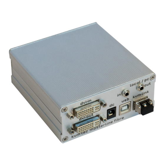
- Page 6 USB connection dvi-out DVI-D connection to monitor Connection for 12 V power supply dvi-out DVI connection to monitor Power/Status lED Displays the status of the extender Power/Status lED Displays the status of the extender 10 | kvm-tec kvm-tec | 11...
- Page 7 1 x SFP Module Multimode up to 500m/1640 ft. RJ45 Socket lEDs * alternativ with Single-Mode up to 20km/12mi Itemnr6831 Yellow Yellow Slow Green Green V. fast * MVX only ** Rem. Only Table 1: Meaning of LED indicators 12 | kvm-tec kvm-tec | 13...
- Page 8 The following mounting kits are available: Rack Mounting Kit RMK-f - Part no. 6130 The rack mounting kit RMK-f is for mounting kvm-tec Smartline SVX and Masterline MVX extenders. It consists of a19“ rack shelf and an alu-faceplate. Rack Mounting Kit RMK-fn - Part no. 6131 The rack mounting kit RMK-fn is for assembling kvm-tec Smartline SVX and Masterline MVX extenders.
- Page 9 Almost done! now connect the audio cable local Audio / out to the PC Audio in and Remote Audio / out with the audio cable to the microphone. HAVE FUN - your kvm-tec Extender is now in use for many years ( MTBF approx 10 years) 6. Audio to PC 5.
- Page 10 Almost done! Now connect the audio cable Local Audio / out to the PC Audio in and Remote Audio / out with the audio cable to the microphone HAVE FUN - your kvm-tec Extender is now in use for many years ( MTBF approx 10 years) 6. Audio to PC 5.
- Page 11 2. Pull the metal latch of the SfP module forwards until it is at a right angle. 2.7 REMoVING A FIbER CAblE 3. Replace the SfP module with the other module. Put the metal latch back in position. Only use SFP modules from kvm-tec, or recommended by kvm-tec. To remove a fiber cable: •...
- Page 12 Overview of all upgrades DDC Option DDC Option Fixed ice position 1020 x 1080 W network Settings network Settings G ExtenderSettings Settings Extender Switching list list of all extenders in the switching system Exit Exit 22 | kvm-tec kvm-tec | 23...
- Page 13 3.3 DETERMINE ThE CURRENT FIRMWARE VERSIoN 3.4 PERFoRMING A FIRMWARE UPDATE To view the firmware version: The latest version of the firmware can be downloaded from http://www.kvm-tec.com/en/ • Make sure the main menu is open. The currently installed firmware versions of the remote support/firmware-download.html.
- Page 14 3. make sure that the update file is directly on the stick and that it is not in any never unplug or plug in the devices during the update. subdirectory 4. the USB stick must be formatted with fAT-32 26 | kvm-tec kvm-tec | 27...
- Page 15 3. extender menu/settings 3. extender menu/settings Plug in the USB stick and wait for a moment Wait until all 4 phases have been completed. 28 | kvm-tec kvm-tec | 29...
- Page 16 The information is then sent to the marked units. During this process the devices can still be in LEDs are then green) operation. As soon as all updates have been transmitted, the marked devices can be restarted and start with the new firmware. 30 | kvm-tec kvm-tec | 31...
- Page 17 The information is then sent to the marked units. During this process the devices can still be in operation. As soon as all updates have been transmitted, the marked devices can be restarted The kvm-tec feature „USB save“ prevents the intrusion of viruses via the USB interface. and start with the new firmware.
- Page 18 • Press 4 through 8 to use a predefined resolution which is saved. 3. Press ESC to go back to the main menu. 3.8 ChANGING ThE NETWoRK SETTINGS See chapter „Switching Menu Settings“. 34 | kvm-tec kvm-tec | 35...
- Page 19 • Press K for automatic adjustment and positioning of the image area. • Press I to reset parameters to default values. • Press S to save the settings and exit the menu. • Press Q to exit without saving. 36 | kvm-tec kvm-tec | 37...
- Page 20 From the Extender Settings menu, press the R key. The Remote Settings menu appears. Press the A key. The Audio Input Gain menu appears. Press arrow left / right to change volume Press arrow up / down to set directio 38 | kvm-tec kvm-tec | 39...
- Page 21 2. Press the R key. The baud Rate menu appears. 3. To select a baud rate press the applicable key. The Enter Parity menu opens. 4. To select a parity rate press the applicable key. 40 | kvm-tec kvm-tec | 41...
-
Page 22: Turn On Or Off Monitor Synchronization
1. From the Extender Settings menu, press the R key. The Remote Settings menu appears. 2. Press the I key to enable or disable the function. 3. Press ESC to go back to the main menu. 42 | kvm-tec kvm-tec | 43... -
Page 23: Using Power Saving Mode
3. When in power saving mode, press any key to return to the menu. • Press E to select English (QWERTY) • Press D to select German (QWERTZ) • Press F to select french (AZERTY) 44 | kvm-tec kvm-tec | 45... -
Page 24: Changing The Keyboard Fallback Mode
3. Use the arrows to select a command. 4. Press E to edit the shortcut. To edit: • Press a single key. Edit the frequency with left and right arrows. - OR - • Press a key combination 46 | kvm-tec kvm-tec | 47... -
Page 25: Switching Between Different Computers
• If the password system is active, the user currently logged in is displayed at the bottom. You can manually logout by pressing the “x” key or disconnect from the current PC by pressing the „d“ key. 48 | kvm-tec kvm-tec | 49... -
Page 26: Network Settings
Some modes require others, and others are incompatible with each other, but the system will automatically recognise this for you. Press the M key to access the network Mode menu. 50 | kvm-tec kvm-tec | 50 kvm-tec | 51... -
Page 27: Disconnect Or Select A Workstation From The Current Connected
• Press the D key to force disconnect the selected device/connection. • Press the E key or Enter key to select a PC or workstation to create or break a connection to that unit. • Press the Q key to exit. 52 | kvm-tec kvm-tec | 53... -
Page 28: Managing User Details, Rights And Groups
• Press the I key to display details about the selected user which may be edited. 1. Make sure the Master View menu is open (see chapter „How to access the network Settings menu (Master View and network Mode)”). 2. Press O to exit the menu. 54 | kvm-tec kvm-tec | 55... -
Page 29: Viewing The Status Of All Remote Units
• Groups: Each user can join up to 8 user groups. Each computer is defined as belonging to one user group. By default all computers are in the same user group. 56 | kvm-tec kvm-tec | 57... -
Page 30: Viewing The Status Of All Local Units
1. Make sure the Master View menu is open (see chapter „How to access the network Settings menu (Master View and network Mode)”). 2. Press the P key. The PC Extender list menu opens. 58 | kvm-tec kvm-tec | 59... -
Page 31: Set Up Dual-Head Or Multi-Head Systems
To achieve this we assign each PC a different group: Department PC: Group 1 Team A PC: Group 2 Team B PC: Group 3 Alex, Blair and Charlie are assigned to be members of Group 1 and Group 2. Danny, Em and 60 | kvm-tec kvm-tec | 61... -
Page 32: Enable User Groups And Rights And Login Access
4. Press the A key to add individual extenders. The extender type is automatically determined once the first extender has been selected. 5. Press the E key to edit the multi-head set name of max. 16 characters. 62 | kvm-tec kvm-tec | 63... -
Page 33: Auto-Connect To A Free Computer After An Interruption
Master View and network Mode“). in the switching menu or by pressing the hot-key combination (see chapter „How to switch 2. Press the C key to disable or enable the option. between different computers“). 64 | kvm-tec kvm-tec | 65... -
Page 34: Enable The User-Pc Binding Mode
To enable the PC Power Down option: 1. Make sure the Network Mode menu is open (see chapter „How to access the switching menu Master View and network Mode“). 2. Press the D key to disable or enable the option. 66 | kvm-tec kvm-tec | 67... -
Page 35: Hide Info Display
Master View and network Mode“). 2. Press the T key to disable or enable the option. 2. Press the h key to disable or enable the option. 4.14 VIDEo ShARING See chapter „How to share videos“. 68 | kvm-tec kvm-tec | 69... -
Page 36: Set The Password Timeout
OUT Establish microphone connection: plug stereo-jack to the microphone input of the PC (pink) connection with local OUT LED is lighting The screen flickers, Install current firmware from our homepage www.kvm-tec.com/ green has an incorrect support/firmware-download display Error... -
Page 37: Requirements For Cables
Green by swaping first the local and than the remote Unit to ano- Check if other units have ther Unit Brown/White the same behaviour Brown Contact kvm-tec Contact kvm-tec support support 72 | kvm-tec kvm-tec | 73... -
Page 38: Requirements Network
The network switch must fulfil the following specifications: 1 Gigabit Switch, with true port to port transfer rates of 1 Gigabit/second A list of kvm-tec tested and recommended switches can be found on our website at www.kvm-tec.com Products - Switching System - Datasheet -recommended Switche... -
Page 39: Maintance & Care , Disposal
By disposing of the packaging and packaging waste in the proper Part nr 9002 Warranty extension to 5 years per SET manner, you help to avoid possible hazards for the environment and public health. 76 | kvm-tec kvm-tec | 77... -
Page 40: Contact Address
10. COnTACT ADDRESS If you have any questions about our products, please contact kvm-tec or your dealer. kvm-tec electronic gmbh Gewerbepark Mitterfeld 1A 2523 Tattendorf Austria Phone: 0043 (0) 2253 81 912 fax: 0043 (0) 2253 81 912 99 Email: support@kvm-tec.com Web: www.kvm-tec.com...
Need help?
Do you have a question about the Master Line MVX Series and is the answer not in the manual?
Questions and answers