Table of Contents
Advertisement
Quick Links
Advertisement
Table of Contents

Subscribe to Our Youtube Channel
Related Manuals for CYBEX Bravo FT-325


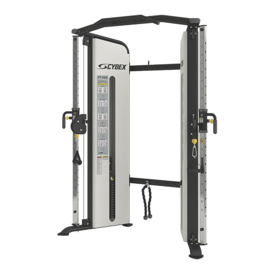
Summary of Contents for CYBEX Bravo FT-325
- Page 1 ® Bravo FT-325 Owner's Manual Part Number 18000-999-4 AD...
- Page 3 International Offices AMERICAS United Kingdom North America Life Fitness UK LTD All Other EMEA Countries and Distributor Business EMEA* Cybex International Inc. Queen Adelaide Bijdorpplein 25-31 Columbia Centre III Ely, Cambs, CB7 4UB 2992 LB Barendrecht 9525 West Bryn Mawr Avenue Telephone: General Office (+44) 1353.666017...
-
Page 4: Table Of Contents
Cybex International, Inc. DISCLAIMER: Cybex International, Inc. makes no representations or warranties regarding the contents of this manual. We reserve the right to revise this document at any time or to make changes to the product described within it without notice or obligation to notify any person of such revisions or changes. -
Page 5: Safety Guidelines And Practices
• Fasteners must have a minimum of 500 lbs. tensile capacity. Cybex recommends .3/8” grade 2 bolts or better. A minimum pull force of 220 lbs/100 kgs is required for each anchor position. -
Page 6: User Safety Precautions
• DO NOT pin weights on selectorized equipment in an elevated position or use the machine if found in this position • DO NOT increase weight resistance on equipment by any means other than those provided by Cybex. • DO NOT wear loose or dangling clothing or jewelry while using equipment. Stay clear of moving parts. -
Page 7: Warnings And Cautions
Warnings and Cautions Warning labels indicate a potentially hazardous situation that could result in serious injury or death if the precautions are not observed. Caution labels indicate a potentially hazardous situation that could result in serious injury or damage to machine if the precautions are not observed. -
Page 8: Label Placement
Label Placement The following diagram shows where each label is located. Description DE000001-X DE000005-X 8500-025-X 1011299-0001 Page 8 of 27... -
Page 9: Assembly
Assembly Machine Specifications Total Weight and Size: 18000 Bravo Weight Machine Dimensions at Rest Machine Dimensions at Use 752 Lbs 58.88” W × 37.20” L × 83.42” H Same 342 Kg 149.55 cm W × 94.49 cm L × 211.89 H Same Maximum User Weight Maximum Training Weight... -
Page 10: Verify Parts List Shown Below
Temperature The unit is designed to function normally in an environment with an ambient temperature range of 50° F (10° C) to 104° F (40° C). The unit can be shipped and stored in an environment with an ambient temperature range of 32° F (0°... -
Page 11: Tools Required
• Fasteners must have a minimum of 500 lbs. tensile capacity. Cybex recommends .3/8” grade 2 bolts or better. A minimum pull force of 220 lbs/100 kgs is required for each anchor position. - Page 12 4. Remove back panels from machine. Description Back panel 5. Verify weight stack pin is disengaged. 6. Remove spiral pin connecting pulley using a hammer and a 3/16” pin punch. Description Cable Pulley bracket Roll pin Top weight connector Weight selector pin 7.
- Page 13 11. Remove plastic insert plug, located at top of machine. Description Plastic plug 12. Loosen the two button head socket cap screws (BHSCS) securing chin up bar to frame using a 7/32” Allen wrench. Description Screw Thread block Chin up bar 13.
- Page 14 15. Move machine to desired position. 16. Reattach frame halves and securely tighten the BHSCS. 17. Place two drops of Loctite #242 to each BHSCS and threaded hole for chin up bar. Securely tighten BHSCS. 18. Insert plastic plugs. Install weight plates 1.
- Page 15 3. Insert a guide pin through each hole of the decals front sheet. A guide pin can be anything that fits through the weight stack hole, such as a weight stack selector pin. 4. Align decals and rub them onto weight plates. 5.
- Page 16 • Fasteners must have a minimum of 500 lbs. tensile capacity. Cybex recommends .3/8” grade 2 bolts or better. A minimum pull force of 220 lbs/100 kgs is required for each anchor position.
-
Page 17: Exercise
Exercise Intended Use The intended commercial use of this machine is to aid exercise and improve general physical fitness. Instructions TIP: Read and understand all instructions and warnings prior to using this machine in the Safety section of the Owner’s Manual. All adjustment points on the machine have yellow handles or knobs. - Page 18 Lat Pull Torso Rotation Arm Curl Page 18 of 27...
- Page 19 Arm Extension Squat Hip Abduction Hip Adduction Page 19 of 27...
-
Page 20: Maintenance
Not inhale or swallow any cleaning product. Protect surrounding area/clothing from exposure. Use in well ventilated area. Follow all product manufacturer’s warnings. Cybex and its vendors cannot be held responsible for damage or injuries resulting from the use or misuse of cleaning products. -
Page 21: Weekly Procedures
Then Dampen a soft white cloth with rubbing alcohol. More Difficult Stains Gently rub stained area. (Alternative Method) Dampen a clean soft cloth in water and rinse area. Apply a light coat of furniture wax for 30 seconds. Restoring Luster Lightly rub area using a clean white cloth. - Page 22 The following conditions may indicate a worn cable: Condition of Cable Diagram A tear or crack in the cable sheath that exposes the cable A kink in the cable A curled sheath Necking - A stretched cable sheath Bars and Handles Inspect bars and handles for wear, paying particular attention to tab area connection points.
-
Page 23: Yearly Procedures
• Hammer • 3/16” Pin punch Four types of cable tension adjustment are used on Cybex Strength Systems: Jam Nut Adjustment This type of adjustment uses a jam nut and a tension adjustment nut at the cable cam end as the primary adjustment. - Page 24 Item Description Qty. Roll pin Top weight connector Cam End Adjustment This type of adjustment uses an adjustment bolt on the pulley bracket. Loosen nut and rotate cam bolt to adjust cable. Item Description Qty. Cam bolt adjustment Page 24 of 27...
-
Page 25: Warranty
Who Pays Transportation and Insurance For Service If the Product or any covered part must be returned to a service facility for repairs, We, Cybex, will pay all transportation and insurance charges for the first year. You are responsible for transportation and insurance charge after the first year. -
Page 26: Effects Of State Laws
Effects of State Laws This warranty gives you specific legal rights, and you may have other rights which vary from state to state and country by country. Warranty Coverage NOTE: There is no warranty coverage for labor on Strength Products. Item 10 Years 5 Years... - Page 27 Columbia Center III - 9525 West Bryn Mawr Ave, Rosemont, IL 60018 • 800-351-3737 • 847-288-3700 • FAX 800-216-8893 www.cybexintl.com...
Need help?
Do you have a question about the Bravo FT-325 and is the answer not in the manual?
Questions and answers