Danfoss Ammonia IPS 8 User Manual
Intelligent purging system
Hide thumbs
Also See for Ammonia IPS 8:
- Technical data, installation and use (28 pages) ,
- User manual (28 pages) ,
- Startup manual (17 pages)

Subscribe to Our Youtube Channel
Related Manuals for Danfoss Ammonia IPS 8


Summary of Contents for Danfoss Ammonia IPS 8
- Page 1 User Guide Intelligent Purging System (IPS 8) Info for UK customers only Danfoss Ltd. Oxford Road, UB9 Ammonia 4LH Denham, UK 230 V AC, 60 Hz Other IPS 8 User Guide languages 148R9653 ir.danfoss.com ir.danfoss.com...
-
Page 2: Table Of Contents
Air traps ............................................8 Connection locations ......................................9 Connection points .........................................11 Installation ..........................................12 Electrical wiring ........................................14 Light Indicators ........................................16 Quick Startup ..........................................17 General display.........................................17 Configuring using the LCD ....................................18 Modbus RTU ..........................................20 Maintenance/Service/Disposal ..................................27 2 | BC344024774466en-000401 © Danfoss | DCS (ms) | 2021.04... -
Page 3: Legal Notice
Title: Product Manager Danfoss only vouches for the correctness of the English version of this declaration. In the event of the declaration being translated into any other language, the translator concerned shall be liable for the correctness of the translation... -
Page 4: Technical Data
40 bar (580 psi) Operating temperature R717 -40 °C to +60 °C (-40 °F to 140 °F) Ordering Unit Code number Danfoss Intelligent Purging System IPS 8 60Hz unit 084H5002 Accessories/Spare parts Accessory Spare part Code Flange blind blank incl Bolts, nuts and Gaskets*... -
Page 5: Introduction
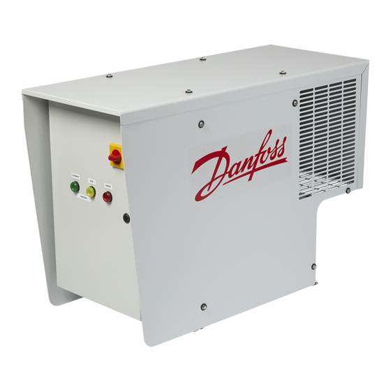
User Guide | Intelligent Purging System (IPS 8) Ammonia Introduction The Danfoss Intelligent Purging System (IPS 8) independent of the main ammonia system and is a stand-alone, self-contained purging unit with only one flange connection to the ammonia designed to remove non-condensable gases plant. -
Page 6: Working Principle
User Guide | Intelligent Purging System (IPS 8) Ammonia Working principle The Danfoss IPS 8 is factory-tested and ready to By condensing the ammonia gas, a new use in ammonia plants with a condenser pressure ammonia/NC gases mix is naturally pulled of more than 6,5 bar (94 psi). -
Page 7: Working Cycle
User Guide | Intelligent Purging System (IPS 8) Ammonia Working cycle The Danfoss IPS 8 operates in 24-hour cycles, of this to be a high concentration of NC gases which 45 minutes are dedicated to an R452A pull and opens the purge solenoid valve. The purge down. -
Page 8: Air Traps
(b). 8 | BC344024774466en-000401 © Danfoss | DCS (ms) | 2021.04... -
Page 9: Connection Locations
HP float valve (6) to the low pressure side (see Fig. 7). Fig. 7 Purger connections (px) & (py). Drain piping (c) must be vertical/downward slope © Danfoss | DCS (ms) | 2021.04 BC344024774466en-000401 | 9... - Page 10 Connect proper resistant piping to the purging outlet pipe and ensure the purged non-condensables are discharged into a water bath of max. 200 liter. 10 | BC344024774466en-000401 © Danfoss | DCS (ms) | 2021.04...
-
Page 11: Connection Points
Single point purging setup is possible (Fig. 09) i.e. NEVER HAVE MORE THAN 1 PURGE POINT OPEN AT A TIME. no solenoid valves with the Danfoss IPS 8 unit. This kind of installation should be installed as Always close one purge valve before opening shown in Fig. -
Page 12: Installation
User Guide | Intelligent Purging System (IPS 8) Ammonia Installation The Danfoss IPS 8 must be installed in Use all 4 lifting eyes and suitable lifting gear accordance with locations recommended in the during installation (unit weight = 100 kg/220 lbs). - Page 13 NC gases more of the purge solenoid valves needs in accordance with local or national regulations. repair or replacement. © Danfoss | DCS (ms) | 2021.04 BC344024774466en-000401 | 13...
-
Page 14: Electrical Wiring
CAN RJ MCX15B Controller Optional 24V DC power supply for (8) purge solenoids (not included) Output terminals for: Up to 8 purge points ICFD drain valve Fig. 16 Controller box internal 14 | BC344024774466en-000401 © Danfoss | DCS (ms) | 2021.04... - Page 15 *When using GD2 24V DC, remove 1-2 and 3-4 bridges between the terminals and connect power supply Fig. 17 Power Supply MCX15B OUTPUT 24V DC 0V DC Fig. 18 Controller MCX15B Inputs and Outputs © Danfoss | DCS (ms) | 2021.04 BC344024774466en-000401 | 15...
-
Page 16: Light Indicators
* The purger continuous purging until max running period (default 160 h) is reached and the purger compressor will stop ** The purger compressor stops when alarm occurs 16 | BC344024774466en-000401 © Danfoss | DCS (ms) | 2021.04... -
Page 17: Quick Startup
Distribution of the actual purging on the various purge points Dis. temp. Actual R452A discharge temperature (°C) Main Window default See above Cycle info Acc. time Purge valve open (h) Past events Last 7 purging events (min) © Danfoss | DCS (ms) | 2021.04 BC344024774466en-000401 | 17... -
Page 18: Configuring Using The Lcd
5 bar 0.5 bar Comp Diff (Hysteresis min allowed ammonia pressure) Limits settings 0 bar 12 bar 6.5 bar Setpoint to start compressor Input/Output Input / Output Display & Config 18 | BC344024774466en-000401 © Danfoss | DCS (ms) | 2021.04... - Page 19 All alarms except (*) activates red light on box outside For alarms not resettable and/or cause not identified, please contact Danfoss Level legend: 0 = Read view, 2 = Installer view (code 200) 3 = Danfoss Service view (Contact Danfoss) © Danfoss | DCS (ms) | 2021.04...
-
Page 20: Modbus Rtu
Short level 2 UNIT CONFIG > COMPRESSOR Pull down time of 3014 Short compressor Delay between purge 3015 2000 1440 Short cycles (single purge) Alarm for endless 3016 Short purging 20 | BC344024774466en-000401 © Danfoss | DCS (ms) | 2021.04... - Page 21 Purge cycle event - counts the accumative minutes that the Read 8121 Event2 -3276,8 3276,7 Minutes Long purge valve has been only open on a finished cycle © Danfoss | DCS (ms) | 2021.04 BC344024774466en-000401 | 21...
- Page 22 32767 °C Short discharge line of only compressor Read 8159 BPLStatus The pressure on R452 -32768 32767 Short only Read 8160 BPHStatus The pressure on R717 -2147483648 2147483647 Short only 22 | BC344024774466en-000401 © Danfoss | DCS (ms) | 2021.04...
- Page 23 Indicates no signal Read 1902 .08 Discharge sensor error from temperature AUTO R. Long only sensor Indicates no signal Read 1902 .09 Suction sensor error from temperature AUTO R. Long only sensor © Danfoss | DCS (ms) | 2021.04 BC344024774466en-000401 | 23...
- Page 24 N.O. Long only Read 1003.04 Valve7 Purge point valve relay N.O. Long only Read 1003.05 Valve8 Purge point valve relay N.O. Long only Read 1003.06 Alarm Alarm relay N.C. only 24 | BC344024774466en-000401 © Danfoss | DCS (ms) | 2021.04...
- Page 25 Disposal of the IPS 8 If an IPS 8 unit is worn out and has to be replaced, the disposal must be done in accordance with national legislation and only done by competent personnel. © Danfoss | DCS (ms) | 2021.04 BC344024774466en-000401 | 25...
- Page 26 26 | BC344024774466en-000401 © Danfoss | DCS (ms) | 2021.04...
Need help?
Do you have a question about the Ammonia IPS 8 and is the answer not in the manual?
Questions and answers