Table of Contents
Advertisement
Quick Links
Advertisement
Table of Contents

Related Manuals for Carus IRIS CAE100 Series


Summary of Contents for Carus IRIS CAE100 Series
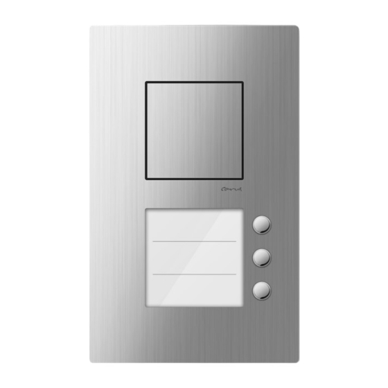
- Page 1 Product information CARUS IRIS Front-door station for surface-mount CAE100x-015x...
-
Page 3: Table Of Contents
Table ofcontents Scope of delivery ................................4 initiation ..................................4 Notes on this product information ................................... 4 Further used symbols ........................................ 4 Safety instructions ............................... 5 General safety regulations ......................................5 requirements to protect against lightning ................................5 Product description ..............................6 Intended use .......................................... -
Page 4: Scope Of Delivery
The product information contains important notes on intended use, installation and initial operation. Please, keep the product information in a suitable place, where it is easily accessible for maintenance and repair reasons. You will find all product information in the download area at www.carus-concepts.com . Used symbols and warning notices... -
Page 5: Safety Instructions
Safety instructions General safety regulations Assembly, installation, commissioning and repair of electronic devices must be carried out by qualified electricians. Observe the latest regulations and standards for system installations. WARNING! Danger of life due to electric shock Observe the safety regulations according to DIN VDE 0100, when working on main power connections of 230 V. -
Page 6: Product Description
Product description Intended use The CAE100x-015x audio front-door stations are suitable for outdoor use. They are suitable for surface-mount. For applications, which differ from the intended use or goes beyond it, the manufacturer accepts no liability. Short description • Front-door station for surface-mount •... -
Page 7: Device Overview
Device overview front back top shell volume control system tone loudspeaker volume control loudspeaker 13 bell button LED error indication 14 nameplate controller light sensor (twilight switch) 15 release screw for name plate holder connection terminal (a, b, R and P) type label lock screw for top shell sticker connections and operation... -
Page 8: Technical Data
Technical data supply voltage +24 V ± 8 % (power supply and control unit) input current in resting position 3-wire operation: I(a) = 0.1 mA, I(P) = 49 mA max. input current: ) = 14.8 mA , I(P ) = 55 mA housing aluminium, anodised natural / silver or black nameplate glass... -
Page 9: Mounting And Installation
Mounting and installation Installation For installing the bottom shell use the installation kit (enclosed in the delivery). • Condensed water must be able to escape and evaporate. Avoid closing the opening for condensed water. • Do not seal the device with silicone rubber under any circumstances. Installation site For an optimal operation we recommend a mounting height of 130 cm to 150 cm (top edge of the device over ground, ill. - Page 10 ► Pull out the nameplate holder (1) (ill. 3). ► Place the nameplate holder on a clean and dry surface. Fig. 3: Removing nameplate holders The top shell is connected to the bottom shell with another hexagon socket screw. ► Loosen the hexagon socket screw (1) by using the allen key (ill. 4). Fig.
-
Page 11: Installing The Bottom Shell
Installing the bottom shell ► Puncture the cellular rubber seal with a pointed object at the posi- tion of the cable gland. ► Guide the connection cable (3) through the cable gland (2) of the bottom shell (ill. 6). ► Install the bottom shell with 4 screws (1) (enclosed in the delivery) to the wall. -
Page 12: Fixing The Top Shell
Fixing the top shell ► Put on the top shell (1) on the bottom shell (2) (ill. 9). The fixing brackets have to latch over the upper edge of the bottom shell. ► Turn down the top shell on the bottom shell. Fig. -
Page 13: Labelling The Nameplate
(ill. 11). we recommend to print the nameplates onto a durable spe- Fig. 11: Replacingnameplates cial foil. You can order replacement foils directly under info@carus- concepts.com. Closing the device ► Push the nameplate holder into the front-door station (see p. 10, ill. -
Page 14: Connecting The Lines
Connecting the lines General information • Use the small slot screwdriver (enclosed in the delivery) to connect lines. Avoid damaging the device. • Ensure that no lines are clamped on the backside of the front-door station or between top and bottom shell. -
Page 15: Initial Operation
Initial operation ► Install the devices of the system completely. ► Proof the a-, b- and P-wire against each other on short-circuit. ► Switch on the mains voltage. Settings • For setting the volume use the enclosed slot screwdriver. • The volumes are set on an average value ex works. A change is not always required. Setting the volume of the system tone ►... -
Page 16: Programming The Bell Buttons
Programming the bell buttons Basic principle All devices at the TCS:BUS have an unique serial number. The serial number of the indoor station is allocated to the bell button of the front-door station. The allocation is stored in the EEPROM of the front-door station. Requirements for the programming: ►... - Page 17 power supply and control unit Switch off the programming mode of the system Shortly press the The programming mode of the system is switched The LED is on. RUN/PROG button. OFF. a) Do not press the RUN/PROG button longer than 5 seconds. Otherwise you will activate the light switch function of the front-door station. The bell button cannot be programmed.
-
Page 18: Cleaning
Cleaning ATTEN- Loss of function due to short-circuit and corrosion. TION! Water and cleaning agents can enter the device. Electronic elements can get damaged due to short- circuit or corrosion. Avoid water and detergents from entering the device! Clean the device with a dry or slightly wet cloth. ATTEN- Damages on the surface of the device TION! -
Page 19: Conformity
Conformity Declarations of conformity are available for download under www.tcsag.de. Information on disposal Dispose the device separately from domestic waste via a collection point for electronic scrap. Ask your county administration for the responsible collection point. Dispose the parts of the packaging in collecting tanks for cardboard and paper resp. plastics. Warranty We offer a simplified processing in case of warranty for qualified electricians. -
Page 20: Service
Service Please send your questions and inquiries to hotline@tcsag.de Headquarters TCS TürControlSysteme AG, Geschwister-Scholl-Str. 7, 39307 Genthin | Germany FON: Fax +49(0)3933 8799/-10 +49(0)3933 8799-11 www.tcsag.de Subject to technical changes. TCS Hotline Germany FON: +49(0)4194 9881-188 FAX: +49 4194 9881-29, time of printing: 06/2015 E-Mail: hotline@tcsag.de PI_CAE100x-015x_uk 1 A...
Need help?
Do you have a question about the IRIS CAE100 Series and is the answer not in the manual?
Questions and answers