
Related Manuals for Carus ARGOS CAE3 02-IP-015 Series


Summary of Contents for Carus ARGOS CAE3 02-IP-015 Series
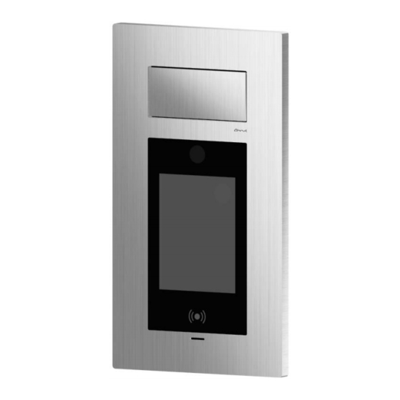
- Page 1 Product information IP video front door station ARGOS CAE3x02-IP-015x 2nd generation...
-
Page 3: Table Of Contents
Table of contents Introduction ........................5 Notes on this product information ..........................5 Used symbols and warning notices ..........................5 Further used symbols ..............................6 Safety instructions ......................6 General safety regulations ............................6 Requirements to protect against lightning ........................6 Note for video surveillance according to DIN 33450 .................... - Page 4 Persons ..................................26 Set up access control with RFID UID ............................27 Set up access control with PIN code ............................27 Access control with RFID UID and PIN code ..........................28 Groups ..................................28 Login/Logout ................................29 Admin password ................................... 29 Special cards ....................................
-
Page 5: Introduction
The product information contains important notes on intended use, installation and initial operation. Please keep the product information at a suitable place, where it is easily accessible for maintenance and repair. All product information are available in the download area under www.carus-concepts.com. Used symbols and warning notices Symbol... -
Page 6: Further Used Symbols
Further used symbols important note or important information ► Step cross reference: For further information on this topic, see source • list, list entry 1 level ‐ list, list entry 2 level Explanation Safety instructions General safety regulations Assembly, installation, commissioning and repair of electronic devices must be carried out by qualified electricians. -
Page 7: Product Description
Product description Intended use The IP video front door station ARGOS is a terminal for access control that combines access control and video door communication. Video door communication can be implemented in a network directly via SIP phones. The IP video front door station ARGOS is suitable for flush-mount in the outdoor area. For applications, which differ from the intended use or go beyond, the manufacturer accepts no liability. - Page 8 • Events: – access control (RFID and/or PIN) – tamper contact (contact, acceleration) – SIP (INFO/DTMF, INVITE, BYE) – trigger inputs – RFID – PIN – TIMER • Actions: – video (PTZ, snapshot) – relay – SIP (INVITE, BYE, TALK) –...
-
Page 9: Device Overview
Device overview housing made of aluminium locking screw loudspeaker RFID reader wall-mount case for surface- and flush-mount microphone pressure compensation element display with touch screen cable gland camera... -
Page 10: Technical Data
Technical data • PoE IEEE 802.3af and 802.3at supply voltage • alternative power supply: 12-55 V DC 10 W (via 2-wire interface) power consumption, in standby P = 6.6 W position maximum power consumption = 9,6 W housing aluminium degree of protection IP65 dimensions (H x W x D in mm) CAE3002-IP-015x:... -
Page 11: Flush-Mount
Flush-mount ► Make a wall cut out for the flush-mount box. Use the flush-mount box as template for the wall cut out. • Do not wall in or foam in the pressure compensa- tion element. • Observe that there is a gap between the masonry and the pressure compensation element. -
Page 12: Connecting The Lines
Connecting the lines For connecting external devices the ARGOS front door station offers different interfaces. (Fig. 5). Pos. designation ethernet connection (PoE power supply) Wiegand: Dat1 Dat0 relays: o.F. 2 WIRE: 2x trigger input Fig. 5: Ports For the installation you can remove the screw termi- nals from the circuit board and pin them back on later. -
Page 13: Put On The Front Plate
Put on the front plate ► Hang the clips (1) of the front plate (2) onto the guidance points (3) of the flush-mount box (4). ► Push the front plate downwards. ► Secure the front plate with the locking screws (5). Fig. -
Page 14: Start Screen
Initial operation WARNING! Danger to life due to electric shock Observe the safety regulations according to DIN VDE 0100, when working on main power con- nections of 230 V. ► Install the devices of the system voltage-free and completely. ► Switch on the mains voltage. •... -
Page 15: Configuration Via Osd Menu
Configuration via OSD menu You need the red RFID card for the configuration via OSD menu (Fig. 10). ► Hold the red RFID card in front of the RFID reader. The configuration menu is displayed (Fig. 11). • If there is no input within 30 sec, the configuration mode is left automatically. -
Page 16: Camera
Camera • In the menu Camera the Live image (1) of the camera is displayed (Fig. 12). • In the menu Camera you can adjust and store 3 different detecting areas (wide angle) of the camera. ► Select the menu Camera from the configuration menu. -
Page 17: Microphone
Microphone The microphone sensitivity offers 2 adjustment options: ‐ digital control (automatic control) ‐ analogue pre-amplification (Fig. 14). We recommend to switch on the automatic adapta- tion, if the local acoustic conditions vary greatly. ► Select the menu Audio from the configuration menu. ►... -
Page 18: Display
Display Automatic control • The bright of the display adapts automatically to the ambi- ent bright. • The measured bright is displayed under the slide (1) switch (Fig. 15). ► Select the menu Display from the configuration menu. ► Slide the slide switch to the position Automatic (1). The bright of the display is adapted automatically to the ambient bright. -
Page 19: Network
Network ► Select the menu IP address from the configuration menu. IP address ► Slide the slide switch (1) to position DHCP ON. The IP ad- dress is allocated to the device automatically. • The IP address can change in the mode DHCP ON during operation. -
Page 20: Intercom Function For Visitor Communication
Intercom function for visitor communication The Intercom function can be used to communicate with visitors, further for employees who, e.g. have forgotten their identification card. Due to the Voice over IP protocol SIP, the device is compatible to modern (video) telephony infrastructure. Thus, no additional end device is needed on the company side. The call can be forwarded to every Voice over IP end device that is accessible per network and SIP. -
Page 21: Control During A Voice Connection
Control during a voice connection • During an active voice connection to a telephone, image phone or Soft phone, orders can be entered via the tele- phone keyboard (Fig. 20). • Depending on the end device, first the transmission of short cuts has to be permitted eventually. -
Page 22: Set Up The Access Control
Set up the access control The device offers 2 technologies for access control: • RFID and/or • access code For assigning access rights to employees, their data needs to be added in the user list of the web inter- face and the accounts have to be released for access control. In the web interface, there are comprehensive help texts to all fields. -
Page 23: Use The Access Control
Use the access control Access via RFID card ► Hold the RFID card in front of the RFID reader. If an as- signed card is recognised, access is granted. The card is recognised with a distance of 1 to 3 cm in front of the device. -
Page 24: Overview Error Messages Rfid Card
Overview error messages RFID card Error message Cause Solution • The device does not know the • Assign the RFID card to the Card not accepted RFID. device. • • Put the missing check mark in Access with card is not released The device does know the RFID card, but no access rights the phone book entry. -
Page 25: Overview Error Messages Access Code
Overview error messages access code Error message Cause Solution • A wrong PIN number was en- • Put in the correct PIN number. wrong PIN number tered. • • Put the missing check mark in Access with access code is not The access code is blocked enabled for user. -
Page 26: Extended Configuration Via Web Interface
Extended configuration via web interface The entire configuration of the device is implemented via the web interface. Thus, the device is equipped with an integrated HTTP server. To use the comfortable configuration via web interface, the device needs to be connected to the Local Area Network (LAN). -
Page 27: Set Up Access Control With Rfid Uid
Fig. 25: Add user The image for the Upload Image has to be a bitmap with 24 or 32 bit. The size of the image has to be 240 x 320 pixels. If you have selected the telephone mode Numeric in the menu Modifications, put in the call num- ber in the text field Pers. -
Page 28: Access Control With Rfid Uid And Pin Code
Access control with RFID UID and PIN code • For security demands the two technologies for access con- trol can be combined. ► Check the box (1) 2-stage. ► Click Save. • If user should no longer be able to have access via card, remove the check mark for RFID. -
Page 29: Login/Logout
Login/Logout Admin password In delivery state the web interface is protected via default password. If you want to assign a new pass- word, you can do this in this menu (Fig. 28). Keep the password carefully. If the password gets lost, you will not be able to access the web interface. -
Page 30: System Status
Option 2: ► Put in the UIDs in the text fields UID green card and UID red card. ► Click SET to store. The risk of wrong inputs is higher in case of a manual input of the UIDs. For this reason, exclu- sively use option 1. -
Page 31: Indication Of The Group Page
Indication of the group page Groups can be displayed in 1 column or 2 columns. Fig. 30: group indication with 1 and 2 columns Phone book mode Here you can determine whether your required contact should be called via phone book or via numeric entry (call number). -
Page 32: Sip Configuration
Fig. 31: Network settings SIP configuration The Intercom function is working according to the Voice-over-IP standard SIP. In combination with an external SIP server, further functions e.g. answering machine and call diversion can be used. A full compatibility of functions from third-party providers cannot be guaranteed. Fig. -
Page 33: Audio/Video
Audio/Video The resolution for MJPG and H.264 can be changed only in the web interface. All settings to transmit audio and video data can be made here. Video formats: • H.264 – is used in combination with SIP • MJPEG, JPEG –... -
Page 34: Interface Configuration
Interface configuration The device is equipped with 2 ports: a relay output and a serial interface. Both can be configured exten- sively. The available call destinations have to be configured previously in the menu User including the SIP URI. Fig. 34: interface configuration... -
Page 35: Upload/Download
Upload/Download Via the menu item Upload/Download a new firmware can be installed on the device. The already in- stalled firmware version can be read off in the menu System status. Files for configuration and access can also be uploaded to or stored in the device. The download of con- figuration files is recommended for safety reasons (Backup) and for similar device configurations. -
Page 36: Information On Disposal
Information on disposal Dispose the device separately from domestic waste via a collection point for electronic scrap. Ask your county administration for the responsible collection point. Dispose the parts of the packaging in collecting tanks for cardboard and paper resp. plastics. Warranty We offer a simplified processing in case of warranty for qualified electricians.
Need help?
Do you have a question about the ARGOS CAE3 02-IP-015 Series and is the answer not in the manual?
Questions and answers