
Related Manuals for Carus Adapto CAI1200


Summary of Contents for Carus Adapto CAI1200
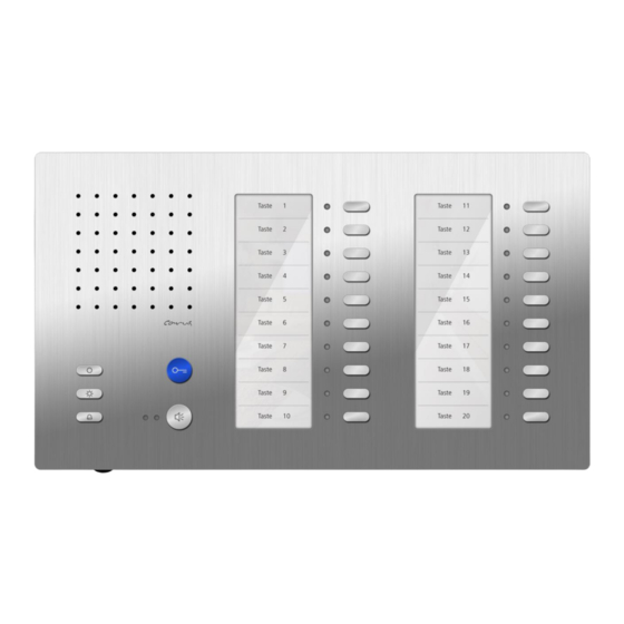
- Page 1 Product information Indoor station for hands-free talking Carus Adapto CAI1200, CAI1210...
-
Page 2: Table Of Contents
Table ofcontents Scope of delivery ....................... 3 Safety instructions ......................3 General safety regulations ....................3 Installation – protective measures ..................3 Technical data ........................4 Device overview ......................... 4 Indication and operating elements ................... 5 Intended use ........................6 Max. -
Page 3: Scope Of Delivery
Scope of delivery 1 x CAI12x0 (top shell, bottom shell or tabletop device) 2 x release bracket 4 x Phillips head screw 4 x dowel assembly instruction Product information instruction manual programming table Safety instructions General safety regulations Attention! Assembly, installation, commissioning and repair of electronic devices must be carried out by qualified electricians and in compliance with the current standards. -
Page 4: Technical Data
Technical data supply voltage: +24 V ± 8 % (power supply and control unit) housing: aluminium anodised (colors as listed in price list) dimensions CAI1200: H 163 mm x W 285 mm x D 16 mm dimensions CAI1210: H 156 mm x W 285 mm x D 150 mm weight: 1404 g (CAI1200), 2136 g (CAI1210) acceptable ambient temperature:... -
Page 5: Indication And Operating Elements
Indication and operating elements Term Function call acceptance, activate speaking, speech button simplex communication end communication ring tone selection (door call front-door station 2 AS > AS- border*) door release (factory setting) door release but- end communication ... -
Page 6: Intended Use
Each with 10 keys. Each function key has its own function function indica- indication. LED is ON when tions a door call comes in an internal call comes in a control function from sensor comes in call diversion is activated ... -
Page 7: Short Description
Short description Basic module blue door release button with floor door release function (can be activated) speech button: for call acceptance and changeover key speaking / listening function key (ex works allocated with control function) with alternative allocation (can be activated) internal call, door release automatic, call diversion ... -
Page 8: Mounting And Installation
Mounting and installation Installation CAI1200 (wall mounting) Attention! The indoor stations have to be (de-)installed only voltage-free! Ensure not to over tighten the screws when installing the wall bottom shell on uneven sur- faces. Otherwise the plate might be deformed. Further, the devices may not be locked into position correctly on the bottom shell. -
Page 9: Deinstall The Device
Install the device Take the device into both hands and position it on the bottom shell. Position the device centrally on the bottom shell and leave out a little space of 10 mm to the bottom edge of the bottom shell. ... -
Page 10: Installation Cai1210 (Tabletop Device)
Installation CAI1210 (tabletop device) Attention! The indoor stations have to be (de-)installed only voltage-free! The table rack is pre-configured and has to be connected to a RJ45 socket. Therefore please note the connection diagram under cable assignment. 1 bottom shell 2 lock pins (4 x) 3 connecting cable... -
Page 11: Install The Device
Install the device Take the device into both hands and position it on the bottom shell. Position the device centrally on the bottom shell and leave out a little space of 10 mm to the bot- tom edge of the bottom shell. ... -
Page 12: Wiring Diagram
Wiring diagram Attention! Observe max. num- ber! (see Intended use, page6) Connection diagram Commissioning Install the devices of the system completely. Check the a-, b- and P-wire against each other for short-circuit. Switch on the main voltage. -
Page 13: Settings
Settings Ring tone selection For 4 different incoming calls (calls from 2 front-door stations, floor call, internal call) the ring tones can be selected. End voice communication: Press call OFF-button and keep it pressed for around 8 s. A positive acknowledgement tone sounds. The ring tone selection is activated. -
Page 14: Factory Settings
Factory settings Ex works the following settings are stored in the device: serial number for parallel call 1000000 function key control function 8 Pre-adjusted times communication time 2 min flashing period of the green LED, if the voice channel is busy after the voice communication is 3 sec 3 x flashing established... -
Page 15: Programming The Basic Module
Programming the basic module Manual programming Legend for programming negative acknowledgement press button shortly (NoProg tone) press the button until... repeat release the button further LEDs off LEDs blinking The programming is realised in four steps: Initiate the programming Pre-selection End-selection End the programming Initiate the programming... - Page 16 Programming func- Pre-selection End-selection tion internal call Execute at the required indoor station: (at function key) press speech button control function 8 (on function key) automatic hands-free talking after internal call switch on (when switched off) or switch off (when switched on) switch on floor door release function (if...
- Page 17 Programming func- Pre-selection End-selection tion block ring tone selec- tion block extended pro- gramming deactivate program- ming lock Attention! Switch on the pro- gramming mode of the system at the BVS first. Execute the steps 1 to 4. ...
-
Page 18: Programming The Function Key Of The Basic Unit With Service Device Tcsk-01
Programming the function key of the basic unit with Service Device TCSK-01 door release automatic call diversion internal call 1 control function 8 parallel allocation activate parallel call switch off NOTE: To deactivate parallel allocation means parallel allocation to serial number 0. ser. -
Page 19: Programming The Function Key Module
Programming the function key module Manual programming Select the Initiate Execute BUS action Select the End program- function, program- (must be executed within function key ming press the ming 40 s after step 1) that should be button ... programmed. Specific door call and door release... -
Page 20: Programming Further Buttons
Programming further buttons Repeat the steps from step 2 on. Ill. 1: Initiate programming Press the call OFF-button on the basic module until NoProg tone sounds and the upper 7 LED start blinking (after around 8 s) release Ill. 2: End the programming mode at the device (or automatically after 40 s) call OFF-button on the basic module: NoProg tone sounds, shortly press... -
Page 21: Programming The Function Key Module Via Service Device Tcsk-01
The labelling stripe can be easily removed to enter the programmed button functions. Insert the complete nameplate carrier back into the guid- ance rail until the cover is locked into place by the magnet- ic holder. Please find suitable labelling templates on our website: www.carus-concepts.com... -
Page 22: General Information On The Conduit In Tcs Audio Systems
General information on the conduit in TCS audio systems The conduit is determined by structural conditions and is only limited by its length Observe when selecting the length of the lines: the loop resistance must not exceed 20 Ω (table). ... -
Page 23: Repair
a, b here short-circuit 20 Ohm: front-door station max. 160 m distance AS/IS-VS by 0.6 mm diameter power supply and control unit max. 280 m distance AS/IS-VS by 0.8 mm diameter indoor station extended function Repair Repairs have to be carried out only by qualified electricians. Cleaning Avoid water from entering the device! Do not use any abrasive detergents! -
Page 24: Warranty
TCS TürControlSysteme AG Subject to technical changes. TCS Hotline Germany Geschwister-Scholl-Str. 7, 39307 Genthin GERMANY FON: +49 3933 8799-10, FAX: +49 3933 -8799-11 FON: +49 4194 9881-188, FAX: +49 4194 9881-29 E-Mail: info@ tcsag.de, www.tcsag.de E-Mail: hotline@tcsag.de www.carus-concepts.com PI_CAI12x0.doc 1 A 02/2014...
Need help?
Do you have a question about the Adapto CAI1200 and is the answer not in the manual?
Questions and answers