
Related Manuals for SportsPlay QUICK SHIP 1 MODIFIED


Summary of Contents for SportsPlay QUICK SHIP 1 MODIFIED
- Page 1 !"#$%&&%$!'"(!"#$)*+$!'"#( ,--./012."( 3*!+4(#5!2(-(67'8!9!:8;( <=0>(?!$5(@)%+4:$(6"'(+&%72;( 2ABCDB(EBCF(GHB(BIGJEB(KCILCA(MBNOEB(MBPJIIJIP(JIDGCAACGJOI=(...
- Page 3 Value Series Installation Guide TAB SECTION INDEX 1. 3D AND 2D DRAWINGS 2. INSTALLATION GUIDE 3. INSTALLATION STEPS 4. COMPONENT INSTALLATION 5. APPENDIX 6. ORIGINAL COMPONENT MAINTENANCE FORMS 7. COMPLETED COMPONENT MAINTENANCE FORMS 2/28/11 V-C_OUTLINE.V1.0211...
- Page 5 Value Series Installation Guide Table of Contents HARDWARE DRAWINGS !"#"$%&'() *************************************************************************************** +! COMPONENT INSTALLATION INSTRUCTION SETS ,-.#"-&(#/'0& ******************************************************************************* 1! APPENDIX FINAL INSTALLATION STEPS 2--,'()#/'0&************************************************************************************ 3! .-4,#'"#/'0&************************************************************************************** 5! MAINTENANCE AND INSPECTION '6789:;<: ********************************************************************************************* =! &>?<#@8A9#9?B?CD?#@8A9#7E;@F98A<G ************************************************ = H?I89?#@8A#J?FC< ************************************************************************************** = 4;I?:@#4A9I;BC<F ********************************************************************************KL! ,88EM#;<G#N;:?9C;EM*************************************************************************KK! H02-$0#H0)'(('() ************************************************************************KO! 4',0#$0PQ'$0N0(,4****************************************************************************KO...
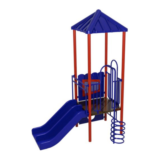
- Page 7 QUICK SHIP 1 (MODIFIED) Installation Guide...
- Page 9 Date Project: QS1_MOD 00-00-10 Size: 9' X 10' E. Barron 5642 Natural Bridge Drawing Number: #911-250 Use Zone: 21' X 22' 800-727-8180 CPSC: Compliant Distributor: SportsPlay Age Group: 2-12 Fax: 314-389-9034 ASTM: Compliant www.sportsplayinc.com Scale: 1:50 Sheet 1 of 1...
- Page 11 Date Project: QS1_MOD 00-00-10 Size: 9' X 10' E. Barron 5642 Natural Bridge Drawing Number: #911-250 Use Zone: 21' X 22' 800-727-8180 CPSC: Compliant Distributor: SportsPlay Age Group: 2-12 Fax: 314-389-9034 ASTM: Compliant www.sportsplayinc.com Scale: 1:50 Sheet 1 of 1...
- Page 13 Date Project: QS1_MOD 00-00-10 Size: 9' X 10' E. Barron 5642 Natural Bridge Drawing Number: #911-250 Use Zone: 21' X 22' 800-727-8180 CPSC: Compliant Distributor: SportsPlay Age Group: 2-12 Fax: 314-389-9034 ASTM: Compliant www.sportsplayinc.com Scale: 1:50 Sheet 1 of 1...
- Page 15 Evaluate the site for drainage. To ensure good drainage around the • storage is required you must store the equipment in a controlled equipment consult a local professional. environment away from heat, moisture and sunlight. SportsPlay recommends carefully unpacking the unit and taking an inventory before 2/28/11 V-C_OUTLINE.V1.0211...
- Page 16 SportsPlay Equipment inc. has provided two warning labels that state: • “WARNING – Installation over a hard surface such as concrete, asphalt or packed earth may result in serious injury or death from falls.”...
- Page 17 100 Bar harbor drive West Conshohocken PA, 19428-2959 Because accidental falls are likely to occur around play equipment, SportsPlay Equipment Inc. recommends that a resilient safety surfacing that will meet standard ASTM F1292 be placed under and around the structure and extend Call –...
- Page 18 Value Series Installation Guide Tools and Materials Drills (1/2” and 3/8”) • List is for tools and materials needed that are not included with the Drill bits and spade bits • playground Levels – Magnetic torpedo and 4’ long levels •...
- Page 19 All SportsPlay Equipment play events have been engineered to meet all The use zone for this equipment shall extend a minimum of 6’ in all directions applicable safety guidelines, but if installed from the perimeter of the equipment.
- Page 20 Value Series Installation Guide The use zone for adjacent stationary equipment may overlap. If the deck height for that equipment is no more than 30” above the protective surfacing the use zone is 6’. The use zone for adjacent stationary equipment may overlap. If the deck height for that equipment is more than 30”...
- Page 21 Value Series Installation Guide Installation Punch List Footing Layout Example 2/28/11 V-C_OUTLINE.V1.0211...
- Page 22 Value Series Installation Guide Step 1: Layout Once the decks are in the desired location within the play area and the decks are flush with each other, mark the locations of the post by inserting a stake into the center of each post location (see drawing below Lay decks on ground in the desired location using the top view layout drawing.
- Page 23 Value Series Installation Guide FOOTING SIDE VIEW Step 3: Deck, Post & Component Installation The easiest way to install the playground is by starting with the central deck and then work out. We recommend installing the posts and central deck and once the post and deck are square and level you may add the concrete (concrete with a minimum of 2,500 psi should be used).
- Page 24 Secure playground area to prevent access while the concrete is setting for a minimum of 48 hours. SportsPlay recommends having a CPSI (certified playground safety inspector) present during installation. If that’s not possible you should have the completed playground (after surfacing is in place) inspected by a CPSI.
- Page 25 Value Series Installation Guide Four Hole Bracket & Panel Bracket Installation FOUR HOLE Tip for installation ATTACHMENT Use the #7 drill bit to pre-drill all holes when connecting the bracket • BRACKET to the post if you are having trouble with the self-tapping screws Installation Always install the brackets with the set screw facing down (refer to •...
- Page 26 Value Series Installation Guide Direct Bolt Deck While two people position and hold the deck in place, insert the deck bolt and washer through the deck and into the factory installed nut on the post. To ensure proper placement, refer to the layout drawing and the post id drawing at the beginning of this guide.
- Page 27 Value Series Installation Guide Other Installation Tips When attaching a deck to a post sometimes the factory installed nuts • will spin when tightening the bolt. If this happens simply slide a slim flathead screw driver in between the deck and the post and slightly pry on the installed nut to keep it from spinning.
- Page 29 Value Series Installation Guide Loose clothing, hoods, strings or jewelry shall be tight or not worn SUPERVISION GUIDE while playing to prevent strangulation. Although the equipment is designed, installed and maintained in accordance with Ensure the temperature of the equipment is not hazardous. Direct all safety guidelines adult supervision is required.
- Page 31 Value Series Installation Guide COMPONENT INSTALLATION INSTRUCTIONS 2/28/11 V-C_OUTLINE.V1.0211...
- Page 33 912-242 SQUARE DECK 46” INSTALLATION INSTRUCTION INSTALLATION DETAILS Recommended crew (Adult): 3 Installation time: 15 min (.75 man hr) User age: 2-12 Use zone: 72” Weight: 79 SURFACING: Use of safety surfacing in compliance with ASTM specification F1292 is required.
- Page 34 912-242 SQUARE DECK 46” INSTALLATION INSTRUCTION PARTS LIST PART # DESCRIPTION Square Deck 46” 913-242 3/8”x1 1/2” Button Head Bolt 126-707BPS 3/8” Flat Washer 316-601 NOTE: Keep a copy of these instructions on file to assist you with maintenance and replacement parts. March 10, 2014...
- Page 35 912-242 SQUARE DECK 46” INSTALLATION INSTRUCTION March 10, 2014...
- Page 36 912-242 SQUARE DECK 46” INSTALLATION INSTRUCTION SPECIFICATIONS INSTALLATION TIPS & TROUBLE SHOOTING Deck-12 GA HRPO steel Should the factory installed nuts on the posts start spinning while trying to attach the decks, simply insert a flat head Hardware – Stainless steel & tamper resistant screw driver under the lip or the nut and tighten the bolt.
- Page 37 912-242 SQUARE DECK 46” INSTALLATION INSTRUCTION BEFORE YOU BEGIN In addition to the components on the packing list you will need a level and blocking material. INSTALLATION STEPS __1) Review all instructions before beginning __2) Unpack, organize, and identify all components: Be sure to place all painted components on a protective surface (cardboard, cloth, etc…) to prevent damage.
- Page 38 912-242 SQUARE DECK 46” INSTALLATION INSTRUCTION INSTALLATION STEPS CONTINUED __6) Once the concrete has set, back fill dirt over the footing holes; inspect the area and components for tools, hazardous debris and sharp edges. Verify all components are installed and all hardware is tight and then install the safety surfacing.
- Page 39 922-126-3 (3’) TRIPLE RAIL SLIDE INSTALLATION INSTRUCTION INSTALLATION DETAILS Recommended crew (Adult): 2 Installation time: 2 Hours (4 man hours) User age: 2-12 Years Use zone: 6’ on all sides Weight: 92lbs SURFACING: Use of safety surfacing in compliance with ASTM specification F1292 is required.
- Page 40 922-126-3 (3’) TRIPLE RAIL SLIDE INSTALLATION INSTRUCTION PARTS LIST PART # DESCRIPTION Triple Rail Slide 3’ Deck 435-612 923-330 Triple Rail Slide Guard 903-214 Slide Legs 913-402 4 Hole Attachment Bracket 905-208 Attachment Bracket Gasket 905-526 Self Tapping Screws 3/8x1” Button Head Bolt 126-703 3/8”...
- Page 41 922-126-3 (3’) TRIPLE RAIL SLIDE INSTALLATION INSTRUCTION FOOTING INFORMATION You must place the bottom of the support post or slide leg on a suitable flat blocking material to prevent it from sinking further into the soil. We recommend you use a brick, block of wood or several inches of gravel.
- Page 42 922-126-3 (3’) TRIPLE RAIL SLIDE INSTALLATION INSTRUCTION March 10, 2014...
- Page 43 INSTALLATION TIPS & TROUBLE SHOOTING Slide – 3/8” walled rotationally molded LLDPE SportsPlay Equipment Inc. recommends pre-drilling the holes in the post when attaching a four-hole bracket with a Paint – Electro statically applied & oven cured powder coat number #7 drill bit.
- Page 44 (Footing depth is 24” less the amount of surfacing used plus the thickness of the blocking material). SportsPlay recommends setting the slide up to the deck and using the slide to mark the position of the slide legs to establish the location of the required footing.
- Page 45 922-126-3 (3’) TRIPLE RAIL SLIDE INSTALLATION INSTRUCTION INSTALLATION STEPS CONTINUED Detail C __5. Attach slide legs (3) to the bottom of the slide by inserting a 3/8” x ¾” bolt (9) and 3/8 washer (8) through the plate on the slide leg (3) and into the factory installed nut on the underneath the exit end of the slide (Detail B).
- Page 46 922-126-3 (3’) TRIPLE RAIL SLIDE INSTALLATION INSTRUCTION INSTALLATION STEPS CONTINUED INSTALLATION STEPS CONTINUED TIP: It’s easier to install the self tapping screws if you pre drill __9. Insert the 3/8 x 3/8 socket set screws (#10) into the threaded the holes in the post with a #7 drill bit by marking the hole hole on the bottom side of the four-hole attachment brackets (#4) locations with a dry erase marker after you have put the guard and tighten (Detail C on page 7).
- Page 47 922-120-3 CORKSCREW 3’ DECK INSTALLATION INSTRUCTION INSTALLATION DETAILS Recommended crew (Adult): 2 Installation time: 1 hr (2 man hrs) User age: 2-12 Use zone: 72 in. in front of climber 72 in to right and left of climber ...
- Page 48 922-120-3 CORKSCREW 3’ DECK INSTALLATION INSTRUCTION PARTS LIST PART # DESCRIPTION Corkscrew 3’ deck 913-443 913-402 Four-Hole Attachment Bracket 905-208 Attachment Bracket Gasket 905-526 Self-Tapping Screw 3/8”x3/8” Set Screw 196-807 3/8”x1” Button Head Bolt 126-703 3/8” Flat Washer 316-601 3/8” Lock Nut 226-602 5/16”x1 ¾”...
- Page 49 922-120-3 CORKSCREW 3’ DECK INSTALLATION INSTRUCTION FOOTING INFORMATION Total footing depth is 24” less the height of the surfacing plus the height of the blocking material. If you were using 12” of surfacing the footing hole would need to be 12” plus the height of the blocking material (refer to the cutaway view to the right).
- Page 50 922-120-3 CORKSCREW 3’ DECK INSTALLATION INSTRUCTION March 11, 2014...
- Page 51 INSTALLATION TIPS & TROUBLE SHOOTING Paint – Electrostatically applied & oven cured powder coat SportsPlay Equipment Inc. recommends pre-drilling the holes in the post when attaching a four-hole bracket with a Hardware – Stainless steel & tamper resistant number #7 drill bit.
- Page 52 922-120-3 CORKSCREW 3’ DECK INSTALLATION INSTRUCTION BEFORE YOU BEGIN In addition to the components on the packing list you will need a shovel or post hole digger, cement, drill, and a level. INSTALLATION STEPS __1) Review all instructions before beginning __2) Unpack, organize and identify, all components: Be sure to place all painted components on a protective surface (cardboard, cloth, etc…) to prevent damage.
- Page 53 922-120-3 CORKSCREW 3’ DECK INSTALLATION INSTRUCTION INSTALLATION STEPS CONTINUED __5) Connect four hole brackets to posts: Now you need to install the Four Hole Brackets to the posts. The top of the barrier, NOT THE ARCH, should be 38” from the surface of the deck to the top of the barrier.
- Page 54 922-120-3 CORKSCREW 3’ DECK INSTALLATION INSTRUCTION INSTALLATION STEPS CONTINUED __8) Install the Corkscrew climber: Place the Corkscrew Climber over the stub on the Arch Wall and secure it with the 5/16” x 1 ¾” Button Head Bolt (9), 5/16” Button Head Nut (10), and 5/16” Lock Washer (11).
- Page 55 922-116-3 (3’) VERTICAL CLIMBER/PROTECTIVE BARRIER INSTALLATION INSTRUCTION INSTALLATION DETAILS Recommended crew (Adult): 2 Installation time: 30 min (1 man hr) User age: 2-12 Use zone: 72 in. in front of climber 72 in to right and left of climber ...
- Page 56 922-116-3 (3’) VERTICAL CLIMBER/PROTECTIVE BARRIER INSTALLATION INSTRUCTION PARTS LIST PART # DESCRIPTION Vertical Climber/3’ Rung Ladder 923-116-3 913-402 Four-Hole Attachment Bracket 905-208 Attachment Bracket Gasket 905-526 Self-Tapping Screw 3/8”x3/8” Set Screw 196-807 3/8”x1” Button Head Bolt 126-703 3/8” Flat Washer 316-601 226-602 Nylon Lock Nut...
- Page 57 SPECIFICATIONS INSTALLATION TIPS & TROUBLE SHOOTING Hardware – Stainless steel & tamper resistant SportsPlay Equipment Inc. recommends pre-drilling the holes in the post when attaching a four-hole bracket with a Attachment Brackets- Electrostatically applied & oven number #7 drill bit. This will make the attachment of the...
- Page 58 922-116-3 (3’) VERTICAL CLIMBER/PROTECTIVE BARRIER INSTALLATION INSTRUCTION BEFORE YOU BEGIN In addition to the components on the packing list you will need a drill, #7 drill bit, tape measure and dry erase marker. INSTALLATION STEPS __1) Review all instructions before beginning: __2) Unpack, organize, and identify all components: Be sure to place all painted components on a protective surface (cardboard, cloth, etc…) to prevent damage.
- Page 59 922-116-3 (3’) VERTICAL CLIMBER/PROTECTIVE BARRIER INSTALLATION INSTRUCTION INSTALLATION STEPS CONTINUED __5) Connect Four-Hole brackets to posts: Now you need to install the Four-Hole Brackets to the posts. The top of the barrier, NOT THE ARCH, should be 38” from the top of the surface of the deck to the top of the barrier.
- Page 60 922-116-3 (3’) VERTICAL CLIMBER/PROTECTIVE BARRIER INSTALLATION INSTRUCTION THIS PAGE WAS INTENTIONALLY LEFT BLANK March 19, 2014...
- Page 61 912-807 SAND & WATER PANEL INSTALLATION INSTRUCTION INSTALLATION DETAILS Recommended crew (Adult): 2 Installation time: User age: Use zone: Weight: 912-807 – 76lbs. SURFACING: Use of safety surfacing in compliance with ASTM specification F1292 is required. MAINTENANCE: ...
- Page 62 912-807 SAND & WATER PANEL INSTALLATION INSTRUCTION PARTS LIST PART # DESCRIPTION 903-225 Sand & Water Panel 903-229 Bubble Basin 12” Acrylic Dome 435-810 1” Leg Support 903-816 913-417 Panel Attachment Bracket 905-208 Gasket for Attachment Bracket 905-526 Self Tapping Screws 905-803 Corner Bracket 5/16”...
- Page 63 912-807 SAND & WATER PANEL INSTALLATION INSTRUCTION FOOTING INFORMATION Total footing depth is 24” less the height of the surfacing plus the height of the blocking material. If you are using 12” of surfacing the footing hole would need to be 12” plus the height of the blocking material.
- Page 64 912-807 SAND & WATER PANEL INSTALLATION INSTRUCTION September 17, 2014...
- Page 65 SPECIFICATIONS INSTALLATION TIPS & TROUBLE SHOOTING Panel- ¾” HDPE UV stabilized plastic SportsPlay Equipment Inc. recommends pre-drilling the holes in the post when attaching a four-hole bracket with a Hardware – Stainless steel & tamper resistant number #7 drill bit. This will make the attachment of the ...
- Page 66 912-807 SAND & WATER PANEL INSTALLATION INSTRUCTION INSTALLATION STEPS __1) You will need to assemble the panel first. To do this you will need the panel (1) and bubble basin (2), three Corner Brackets (8), six 5/16” Washers (9), six 5/16” x 3/4” Button Head Bolt (10), six 5/16”...
- Page 67 912-807 SAND & WATER PANEL INSTALLATION INSTRUCTION INSTALLATION STEPS CONTINUED __4) Install panel to attachment brackets: Once you have all 4 of the panel attachment brackets installed. Locate the panel, with a helper lift the panel into place and mark the holes in the tab of the panel attachment bracket on the panel.
- Page 68 912-807 SAND & WATER PANEL INSTALLATION INSTRUCTION INSTALLATION STEPS CONTINUED __7) Install the Acrylic Domes in Bubble Basin To complete this step you will need the two 12” acrylic domes with the drain assemblies installed in the previous step. You will also need sixteen 3/8”...
- Page 69 912-881 MUSIC PANEL INSTALLATION INSTRUCTION INSTALLATION DETAILS ! Recommended crew (Adult): 2 ! Installation time: 1 Hour (2 man hrs) ! User age: 2-12 Years ! Use zone: NA ! Weight: 41 SURFACING: Use of safety surfacing in compliance with ASTM specification F1292 is required.
- Page 70 912-881 MUSIC PANEL INSTALLATION INSTRUCTION PARTS LIST PART # DESCRIPTION 913-509 Music Panel 913-417 Panel Attachment Bracket 905-208 Gasket for Attachment Bracket 905-526 Self Tapping Screws 316-501 5/16” Flat Washer 116-529 5/16”x3/4” Button Head Bolt 216-512 5/16”x1” Button Head Bolt 316-601 3/8”...
- Page 71 INSTALLATION INSTRUCTION INSTALLATION TIPS & TROUBLE SHOOTING SPECIFICATIONS ! SportsPlay Equipment Inc. recommends pre-drilling the Panel- !” HDPE UV stabilized plastic holes in the post when attaching a four-hole bracket with a number #7 drill bit. This will make the attachment of the Hardware –...
- Page 72 912-881 MUSIC PANEL INSTALLATION INSTRUCTION BEFORE YOU BEGIN In addition to the components on the packing list you will need a drill with a !” drill bit and a dry erase marker ----. INSTALLATION STEPS __1) Review all instructions before beginning __2) Unpack, organize, and identify all components.
- Page 73 912-881 MUSIC PANEL INSTALLATION INSTRUCTION INSTALLATION STEPS CONTINUED ____4) Attach panel attachment brackets You will need the four panel attachment brackets (2), four attachment bracket gaskets (3), sixteen self tapping screws (4). Determine the proper placement for the panel attachment brackets. (This will vary with different deck heights and locations).
- Page 74 912-881 MUSIC PANEL INSTALLATION INSTRUCTION INSTALLATION STEPS CONTINUED __7) Install the panel Locate the four 5/16” flat washers (5), 5/ four 16x3/4” button head bolt (6), four 5/16x1” button head nuts (7), four 3/8” flat washers and locktite. Lift the panel up to the panel attachment brackets and secure it with the hardware listed in this step.
- Page 75 912-275 PYRAMID ROOF INSTALLATION INSTRUCTION INSTALLATION DETAILS Recommended crew (Adult): 2 Installation time: 1 hr (2 man hrs) User age: 2-12 Use zone: NA Weight: 92 lbs SURFACING: Use of safety surfacing in compliance with ASTM specification F1292 is required.
- Page 76 912-275 PYRAMID ROOF INSTALLATION INSTRUCTION PARTS LIST PART # DESCRIPTION 435-635 Pyramid Roof 913-430 Roof Bracket 516-200 Zip Togglers 3/8” x 2” Button Head Bolts 116-608 3/8” flat Washers 316-601 905-526 Self Tapping Screws NOTE: Keep a copy of these instructions on file to assist you with maintenance and replacement parts.
- Page 77 INSTALLATION TIPS & TROUBLE SHOOTING Paint – Electrostatically applied & oven cured powder coat SportsPlay Equipment Inc. recommends pre-drilling the holes in the post when attaching a four-hole bracket with a Hardware – Stainless steel & tamper resistant number #7 drill bit.
- Page 78 912-275 PYRAMID ROOF INSTALLATION INSTRUCTION BEFORE YOU BEGIN In addition to the components on the packing list you will need a drill and 3/4” drill bit, tape measure, marker, and a ladder. INSTALLATION STEPS __1) Review all instructions before beginning: __2) Unpack, organize, and identify all components: Be sure to place all painted components on a protective surface (cardboard, cloth, etc…) to prevent damage.
- Page 79 912-275 PYRAMID ROOF INSTALLATION INSTRUCTION INSTALLATION STEPS CONTINUED __6) Drill holes into the Pyramid Roof: Rotate the Pyramid Roof to allow access to the marks you made in the previous step. Drill each of the eight marks with the 3/4” drill bit. Install a Zip Toggler (3) into each of the holes.
- Page 80 912-275 PYRAMID ROOF INSTALLATION INSTRUCTION THIS PAGE WAS INTENTIONALLY LEFT BLANK April 30, 2014...
- Page 81 VALUE SERIES INSTALLATION APPENDIX INSTALLATION APPENDIX 4/2/10 M-C_APPENDIX.V1.0410...
- Page 83 VALUE SERIES INSTALLATION APPENDIX Loose fill surfacing material must be maintained at the required depth within the use zone. Loose fill material must be replaced FINAL INSTALLATION STEPS or added as necessary to maintain its resilient properties. __1. Once the entire playground has been assembled level and square each post, deck and component.
- Page 84 VALUE SERIES INSTALLATION APPENDIX LABEL INSTALLATION SportsPlay Equipment Inc. has included multiple labels that must be installed on the playground structure as recommended by ASTM. There are four different labels that, as the owner you are required to install and maintain. If a label becomes damaged please contact your distributor for replacement.
- Page 85 The component maintenance sheets and a general inspection SportsPlay Equipment does not manufacture surfacing and checklist are included in the next section of this booklet and as is only providing this information on surfacing as a guide the owner it is your responsibility to ensure that you have a for safety.
- Page 86 The first form is the General Inspection checklist. This form will cover the basic inspection of the play equipment and area. SportsPlay recommends performing this inspection daily as it covers basic safety of the equipment and area. Documenting this inspection is up to you but you can simply laminate a copy and mark each item with a dry erase marker before allowing access to the area.
- Page 87 VALUE SERIES INSTALLATION APPENDIX ORIGINAL INSPECTION AND MAINTENANCE FORMS 4/2/10 M-C_APPENDIX.V1.0410...
- Page 89 VALUE SERIES INSTALLATION APPENDIX ___No loose or missing hardware GENERAL INSPECTION CHECKLIST ___Moving parts (example: swings) are not worn ___Adequate surfacing under and around ___Swing chains are not looped over the top bar of the swing equipment ___Surfacing material is in good condition ___There are no modifications to the playground ___Ensure surfacing materials are not compacted (rake and ___No strings or rope tied to the equipment...
- Page 90 • You will perform this inspection when performing your component inspections Replacement Parts • Contact your distributor to order new labels. If unable to contact distributor please call SportsPlay Equipment for replacements: 1- 314-389-4140 • Before calling be sure to identify the proper part, part number and quantity needed •...
- Page 91 GENERAL FOOTING MAINTENANCE Footings • Move surfacing (if loose fill) to expose the footing • Inspect concrete for cracks or loose supports o If cracked footings or loose supports are found you must excavate the soil around the concrete, remove the concrete and pour a new footing •...
- Page 92 GENERAL FOOTING MAINTENANCE INSPECTION FORM ! MAKE COPIES OF THIS FORM TO USE FOR INSPECTION ! REVIEW THE “MAINTENANCE GUIDE” IN THE APPENDIX TO BETTER UNDERSTAND THE IMPORTANCE OF MAINTENANCE AND HOW TO DEVELOP A MAINTENANCE SCHEDULE. ! DOCUMENT ALL MAINTENANCE ACTIONS ON THE LIST AS WELL AS ANY NOT LISTED. ! INCLUDE DATES AND SIGNATURES Inspection Checklist Recommended...
- Page 93 If any of the labels are worn or • missing order replacements Replacement Parts ! Contact your distributor to order new labels. If unable to contact distributor please call SportsPlay Equipment for replacements: 1-314-389-4140 February 17, 2010...
- Page 94 LABEL MAINTENANCE INSPECTION FORM ! MAKE COPIES OF THIS FORM TO USE FOR INSPECTION ! REVIEW THE “MAINTENANCE GUIDE” IN THE APPENDIX TO BETTER UNDERSTAND THE IMPORTANCE OF MAINTENANCE AND HOW TO DEVELOP A MAINTENANCE SCHEDULE. ! DOCUMENT ALL MAINTENANCE ACTIONS ON THE LIST AS WELL AS ANY NOT LISTED. ! INCLUDE DATES AND SIGNATURES Inspection Checklist Recommended...
- Page 95 • ! Contact your distributor to order the concrete footing new labels. If unable to contact o Review the footing maintenance distributor please call SportsPlay document for repair procedure Equipment for replacements: should you discover a post is not 1-314-389-4140...
- Page 96 POST MAINTENANCE INSPECTION FORM ! MAKE COPIES OF THIS FORM TO USE FOR INSPECTION ! REVIEW THE “MAINTENANCE GUIDE” IN THE APPENDIX TO BETTER UNDERSTAND THE IMPORTANCE OF MAINTENANCE AND HOW TO DEVELOP A MAINTENANCE SCHEDULE. ! DOCUMENT ALL MAINTENANCE ACTIONS ON THE LIST AS WELL AS ANY NOT LISTED. ! INCLUDE DATES AND SIGNATURES Inspection Checklist Recommended...
- Page 97 Contact distributor of color matching paint. Contact Distributor for Thermoplastic repair kit. ! Order new hardware from SportsPlay Equipment Inc. Surfacing - Refer to the surfacing maintenance sheet. Replacement Parts ! Reference the parts list on page 2 of the instruction set for this component to identify the part/s correctly.
- Page 98 922-177 SQUARE DECK EQUIPMENT MAINTENANCE INSPECTION FORM ! MAKE COPIES OF THIS FORM TO USE FOR INSPECTION ! REVIEW THE “MAINTENANCE GUIDE” IN THE APPENDIX TO BETTER UNDERSTAND THE IMPORTANCE OF MAINTENANCE AND HOW TO DEVELOP A MAINTENANCE SCHEDULE. ! DOCUMENT ALL MAINTENANCE ACTIONS ON THE LIST AS WELL AS ANY NOT LISTED. ! INCLUDE DATES AND SIGNATURES Inspection Checklist Recommended...
- Page 99 922-124 (3’) TRIPLE RAIL SLIDE EQUIPMENT MAINTENANCE Brackets Welds ! Inspect all four-hole clamps and ! Inspect all welds for cracks. If a crack is found panel clamps. block access to the playground and contact your ! Ensure the setscrews are tight and distributor for replacement parts immediately.
- Page 100 922-124 (3’) TRIPLE RAIL SLIDE EQUIPMENT MAINTENANCE INSPECTION FORM ! MAKE COPIES OF THIS FORM TO USE FOR INSPECTION ! REVIEW THE “MAINTENANCE GUIDE” IN THE APPENDIX TO BETTER UNDERSTAND THE IMPORTANCE OF MAINTENANCE AND HOW TO DEVELOP A MAINTENANCE SCHEDULE. ! DOCUMENT ALL MAINTENANCE ACTIONS ON THE LIST AS WELL AS ANY NOT LISTED.
- Page 101 922-116-3 VERTICAL CLIMBER/PROTECTIVE BARRIER EQUIPMENT MAINTENANCE Brackets Welds ! Inspect all four-hole clamps and ! Inspect all welds for cracks. If a crack is found panel clamps. block access to the playground and contact your ! Ensure the setscrews are tight and distributor for replacement parts immediately.
- Page 102 922-116-3 VERTICAL CLIMBER/PROTECTIVE BARRIER EQUIPMENT MAINTENANCE INSPECTION FORM ! MAKE COPIES OF THIS FORM TO USE FOR INSPECTION ! REVIEW THE “MAINTENANCE GUIDE” IN THE APPENDIX TO BETTER UNDERSTAND THE IMPORTANCE OF MAINTENANCE AND HOW TO DEVELOP A MAINTENANCE SCHEDULE. ! DOCUMENT ALL MAINTENANCE ACTIONS ON THE LIST AS WELL AS ANY NOT LISTED.
- Page 103 922-120-3 (3’) CORKSCREW CLIMBER EQUIPMENT MAINTENANCE Brackets Welds ! Inspect all four-hole clamps and ! Inspect all welds for cracks. If a crack is found panel clamps. block access to the playground and contact your ! Ensure the setscrews are tight and distributor for replacement parts immediately.
- Page 104 922-120-3 (3’) CORKSCREW CLIMBER EQUIPMENT MAINTENANCE INSPECTION FORM ! MAKE COPIES OF THIS FORM TO USE FOR INSPECTION ! REVIEW THE “MAINTENANCE GUIDE” IN THE APPENDIX TO BETTER UNDERSTAND THE IMPORTANCE OF MAINTENANCE AND HOW TO DEVELOP A MAINTENANCE SCHEDULE. ! DOCUMENT ALL MAINTENANCE ACTIONS ON THE LIST AS WELL AS ANY NOT LISTED.
- Page 105 912-807 SAND & WATER PANEL EQUIPMENT MAINTENANCE Brackets Welds ! Inspect all four-hole clamps and ! Inspect all welds for cracks. If a crack is found panel clamps. block access to the playground and contact your ! Ensure the setscrews are tight and distributor for replacement parts immediately.
- Page 106 912-807 SAND & WATER PANEL EQUIPMENT MAINTENANCE INSPECTION FORM ! MAKE COPIES OF THIS FORM TO USE FOR INSPECTION ! REVIEW THE “MAINTENANCE GUIDE” IN THE APPENDIX TO BETTER UNDERSTAND THE IMPORTANCE OF MAINTENANCE AND HOW TO DEVELOP A MAINTENANCE SCHEDULE. ! DOCUMENT ALL MAINTENANCE ACTIONS ON THE LIST AS WELL AS ANY NOT LISTED.
- Page 107 912-881 MUSIC PANEL EQUIPMENT MAINTENANCE Brackets Welds ! Inspect all four-hole clamps and ! Inspect all welds for cracks. If a crack is found panel clamps. block access to the playground and contact your ! Ensure the setscrews are tight and distributor for replacement parts immediately.
- Page 108 912-881 MUSIC PANEL EQUIPMENT MAINTENANCE INSPECTION FORM ! MAKE COPIES OF THIS FORM TO USE FOR INSPECTION ! REVIEW THE “MAINTENANCE GUIDE” IN THE APPENDIX TO BETTER UNDERSTAND THE IMPORTANCE OF MAINTENANCE AND HOW TO DEVELOP A MAINTENANCE SCHEDULE. ! DOCUMENT ALL MAINTENANCE ACTIONS ON THE LIST AS WELL AS ANY NOT LISTED. ! INCLUDE DATES AND SIGNATURES Inspection Checklist Recommended...
- Page 109 922-275 PYRAMID ROOF EQUIPMENT MAINTENANCE Brackets Welds ! Inspect all four-hole clamps and ! Inspect all welds for cracks. If a crack is found panel clamps. block access to the playground and contact your ! Ensure the setscrews are tight and distributor for replacement parts immediately.
- Page 110 922-275 PYRAMID ROOF EQUIPMENT MAINTENANCE INSPECTION FORM ! MAKE COPIES OF THIS FORM TO USE FOR INSPECTION ! REVIEW THE “MAINTENANCE GUIDE” IN THE APPENDIX TO BETTER UNDERSTAND THE IMPORTANCE OF MAINTENANCE AND HOW TO DEVELOP A MAINTENANCE SCHEDULE. ! DOCUMENT ALL MAINTENANCE ACTIONS ON THE LIST AS WELL AS ANY NOT LISTED. ! INCLUDE DATES AND SIGNATURES Inspection Checklist Recommended...
- Page 111 VALUE SERIES INSTALLATION APPENDIX COMPLETED INSPECTION AND MAINTENANCE FORMS 4/2/10 M-C_APPENDIX.V1.0410...
Need help?
Do you have a question about the QUICK SHIP 1 MODIFIED and is the answer not in the manual?
Questions and answers