
Related Manuals for SportsPlay LAUREN


Summary of Contents for SportsPlay LAUREN
- Page 1 !"#$%&&%$!'"(!"#$)*+$!'"#( ,'-.&(&%*)."(( /0(1!$2(3)%+4.$(5"'(+&%,67( #$%"-%)-(&%8'*$( 69:;<:(=:;>(?@:(:A?B=:(C;AD;9(E:FG=:(E:HBAABAH(BA<?;99;?BGAI(...
- Page 3 MEGA Series Installation Guide TAB SECTION INDEX 1. 3D AND 2D DRAWINGS 2. INSTALLATION GUIDE 3. INSTALLATION STEPS 4. COMPONENT INSTALLATION 5. APPENDIX 6. ORIGINAL COMPONENT MAINTENANCE FORMS 7. COMPLETED COMPONENT MAINTENANCE FORMS 4/2/10 M-C_OUTLINE.V1.0410...
- Page 5 MEGA Series Installation Guide Table of Contents HARDWARE DRAWINGS COMPONENT INSTALLATION INSTRUCTION SETS !"#$%&'()$ **************************************************************************************** +! APPENDIX ,-./0&12&!1340345 ******************************************************************************* 6! FINAL INSTALLATION STEPS MAINTENANCE AND INSPECTION 67&7%(89:) *************************************************************************************** ;! ,"'&7"8:	$8 ******************************************************************************* <! ="",9:)	$8************************************************************************************ >! '"?,&97	$8************************************************************************************** @! 9AB1C4-34 ********************************************************************************************* D! E021C0&F1G&E0HI3************************************************************************************** D ?-204J&?GC2-KI3H ********************************************************************************+L! ,11/5&-3M&N-40CI-/5*************************************************************************++! E$="%$&E$)9::9:) ************************************************************************+O!
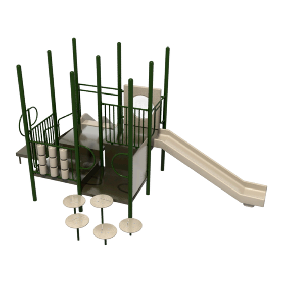
- Page 7 MODEL LAUREN Installation Guide...
- Page 9 !!" )*-//0,1 )*+,-. $#%&%(# <0,1-6=>3?- @3,-4 $#%&%'% 50I=53I=5+- @3,-4 $#%&#%# :;367 :;367 9344 9344 $#%&#!8 $#%&#!8 QB4L=9344 )*6301G* 563,.H-6 )407- )*3*0+, $#%&%#E $#%&%8F A;BB4- @3,-4 $#%&##( 560/4- 2304 )407- $#%&%'! !"#$%&'()* !"#$%&'()* !"#$%&'()* !"#$%&'()* @6+O-I*D=P3;6-, Q63K,=AMD Q3*- =============>-13=S43N/4-..= '8&#'&#' )0?-D=%#"=V=#$" R770- 8JE%=U3*;634=A6071- F''&(%(&F#F'...
- Page 11 !!" !"#$%&'()* !"#$%&'()* !"#$%&'()* !"#$%&'()* @;2A041'(B%C;0> D;%7>(F<' D%10 ((((((((((((((J0K%(L5%?:5099 -I*#-*#- .=R0'(O#"(S(#," GHH=0 I6)O(P%1C;%5(F;=HK0 +--*QOQ*+#+- L@.L'(L2?:5=%>1 D=91;=EC12;'( T90(U2>0'(!!"(S(!#" $%&'(!#)*!+,*,-!) M.NJ'(L2?:5=%>1 77789:2;19:5%<=>4842? .4%50'(#',6 ./001(#(23(# "...
- Page 13 @" !"#$%&'()* !"#$%&'()* !"#$%&'()* !"#$%&'()* @;2A041'(B%C;0> D;%7>(F<' D%10 (((((((((((((J0K%(L5%?:5099( -I*"-*"- .=R0'(O"#(S(",# GHH=0 I6)O(P%1C;%5(F;=HK0 +--*QOQ*+"+- L@.L'(L2?:5=%>1 D=91;=EC12;'( T90(U2>0'(!!#(S(!"# $%&'(!")*!+,*,-!) M.NJ'(L2?:5=%>1 77789:2;19:5%<=>4842? .4%50'("',6 ./001("(23(" "...
- Page 15 Care should be taken with all powder coated and thermoplastic-coated parts to prevent damage to the coating. SportsPlay Equipment inc. has provided two warning labels that state: • Additionally all plastic panels need to be stored flat to prevent warping.
- Page 16 MEGA Series Installation Guide SportsPlay will provide manufacturer identification labels that must be • installed on the structure during installation per ASTM F1487. Installation instructions for these labels are included in the appendix of this instruction manual. Labels must be replaced when they are no longer legible. Contact your •...
- Page 17 CONCRETE, ASPHALT OR PACKED EARTH MAY RESULT IN SERIOUS INJURY OR DEATH FROM A FALL Call – 618-832-9585 Because accidental falls are likely to occur around play equipment, SportsPlay Equipment Inc. recommends that a resilient safety surfacing that will meet Web Site –...
- Page 18 MEGA Series Installation Guide Tools and Materials Drills (1/2” and 3/8”) • List is for tools and materials needed that are not included with the Drill bits and spade bits • playground Levels – Magnetic torpedo and 4’ long levels •...
- Page 19 MEGA Series Installation Guide BEFORE STARTING INSTALLATION OF YOUR PLAYGROUND, All SportsPlay Equipment play events have been engineered to meet all applicable PLEASE READ INSTRUCTIONS THOROUGHLY. safety guidelines, but if installed Improperly, these problems may occur: BEFORE BEGINNING • Entrapment gaps (between 3 1/2” and 9”) String Entanglements •...
- Page 20 MEGA Series Installation Guide The use zone for this equipment shall extend a minimum of 6’ in all directions from the perimeter of the equipment. The use zone for adjacent stationary equipment may overlap. If the deck height for that equipment is no more than 30” above the protective surfacing the use zone is 6’.
- Page 21 MEGA Series Installation Guide Installation Punch List Footing Layout Example 4/2/10 M-C_OUTLINE.V1.0410...
- Page 23 MEGA Series Installation Guide Step 1: Layout Once the decks are in the desired location within the play area and the decks are flush with each other, mark the locations of the post by inserting a stake into the center of each post location (see drawing below Lay decks on ground in the desired location using the top view layout drawing.
- Page 24 MEGA Series Installation Guide FOOTING SIDE VIEW Step 3: Deck, Post & Component Installation The easiest way to install the playground is by starting with the central deck and then work out. We recommend installing the posts and central deck and once the post and deck are square and level you may add the concrete (concrete with a minimum of 2,500 psi should be used).
- Page 25 Secure playground area to prevent access while the concrete is setting for a minimum of 48 hours. SportsPlay recommends having a CPSI (certified playground safety inspector) present during installation. If that’s not possible you should have the completed playground (after surfacing is in place) inspected by a CPSI.
- Page 27 MEGA Series Installation Guide Four Hole Bracket & Panel Bracket Installation FOUR HOLE Tip for installation ATTACHMENT Use the #7 drill bit to pre-drill all holes when connecting the bracket • BRACKET to the post if you are having trouble with the self-tapping screws Installation Always install the brackets with the set screw facing down (refer to •...
- Page 28 MEGA Series Installation Guide Direct Bolt Deck While two people position and hold the deck in place, insert the deck bolt and washer through the deck and into the factory installed nut on the post. To ensure proper placement, refer to the layout drawing and the post id drawing at the beginning of this guide.
- Page 29 MEGA Series Installation Guide Other Installation Tips When attaching a deck to a post sometimes the factory installed nuts • will spin when tightening the bolt. If this happens simply slide a slim flathead screw driver in between the deck and the post and slightly pry on the installed nut to keep it from spinning.
- Page 31 MEGA Series Installation Guide SUPERVISION GUIDE Loose clothing, hoods, strings or jewelry shall be tight or not worn while playing to prevent strangulation. Although the equipment is designed, installed and maintained in accordance with all safety guidelines adult supervision is required. Ensure the temperature of the equipment is not hazardous.
- Page 33 HARDWARE...
- Page 37 MEGA Series Installation Guide COMPONENT INSTALLATION INSTRUCTIONS 4/2/10 M-C_OUTLINE.V1.0410...
-
Page 39: Installation Details
922-177 SQUARE DECK 48” FOR 5”CLAMPLESS SYSTEM INSTALLATION INSTRUCTION INSTALLATION DETAILS ! Recommended crew (Adult): 3 ! Installation time: 15 min (.75 man hr) ! User age: 2-12 ! Use zone: 72” ! Weight: 79 SURFACING: Use of safety surfacing in compliance with ASTM specification F1292 is required MAINTENANCE: ! As the owner of the playground you are responsible for... -
Page 40: Parts List
922-177 SQUARE DECK 48” FOR 5”CLAMPLESS SYSTEM INSTALLATION INSTRUCTION PARTS LIST PART # DESCRIPTION 923-177 Square Deck 48” for 5” Clamp less system 126-703 3/8”x1” Button Head Bolt 316-601 3/8” Flat Washer NOTE: Keep a copy of these instructions on file to assist you with maintenance and replacement parts. - Page 41 922-177 SQUARE DECK 48” FOR 5”CLAMPLESS SYSTEM INSTALLATION INSTRUCTION February 17, 2010...
-
Page 42: Specifications
922-177 SQUARE DECK 48” FOR 5”CLAMPLESS SYSTEM INSTALLATION INSTRUCTION INSTALLATION TIPS & TROUBLE SHOOTING SPECIFICATIONS ! Should the factory installed nuts on the posts start spinning ! Deck-12 GA HRPO steel while trying to attach the decks, simply insert a flat head screw driver under the lip or the nut and tighten the bolt. -
Page 43: Before You Begin
922-177 SQUARE DECK 48” FOR 5”CLAMPLESS SYSTEM INSTALLATION INSTRUCTION BEFORE YOU BEGIN In addition to the components on the packing list you will need a level and blocking material. INSTALLATION STEPS __1) Review all instructions before beginning __2) Unpack, organize, and identify all components: Be sure to place all painted components on a protective surface (cardboard, cloth, etc…) to prevent damage. - Page 44 922-177 SQUARE DECK 48” FOR 5”CLAMPLESS SYSTEM INSTALLATION INSTRUCTION INSTALLATION STEPS CONTINUED __6) Once the concrete has set, back fill dirt over the footing holes; inspect the area and components for tools, hazardous debris and sharp edges. Verify all components are installed and all hardware is tight and then install the safety surfacing.
- Page 45 922-135 3’ TRANSFER STATION INSTALLATION INSTRUCTION INSTALLATION DETAILS ! Recommended crew (Adult): 2 ! Installation time: 1.5 hr (3 man hrs) ! User age: 5-12 ! Use zone: 72” from all edges of deck ! Weight: 165 lbs SURFACING: Use of safety surfacing in compliance with ASTM specification F1292 is required.
- Page 46 922-135 3’ TRANSFER STATION INSTALLATION INSTRUCTION PARTS LIST PART # DESCRIPTION 923-206 3’ Transfer Station Stairs 923-211 Transfer Station Platform 923-210 Transfer Station Step 923-209 Transfer Station Cover Plate 923-208 Transfer Station Support Post 913-230 Transfer Point Inside Leg 913-426 Transfer Point Handhold Post 913-202 Transfer Point Handrail Left 3’...
- Page 47 922-135 3’ TRANSFER STATION INSTALLATION INSTRUCTION FOOTING INFORMATION ! Total footing depth is 24” less the height of the surfacing plus the height of the blocking material. If you are using 12” of surfacing the footing hole would need to be 12” plus the height of the blocking material (refer to both the side and front cutaway views to the right).
- Page 48 922-135 3’ TRANSFER STATION INSTALLATION INSTRUCTION February 17, 2010...
- Page 49 INSTALLATION TIPS & TROUBLE SHOOTING ! Deck and Steps-12 GA HRPO steel ! SportsPlay Equipment Inc. recommends pre-drilling the holes in the post when attaching a four-hole bracket with a ! Deck & Step Coating – Electrostatically applied & oven number #7 drill bit.
- Page 50 922-135 3’ TRANSFER STATION INSTALLATION INSTRUCTION BEFORE YOU BEGIN In addition to the components on the packing list you will need a level, blocking material, 9/16 wrench, shovel, tape measure and a post hole digger. INSTALLATION STEPS __1) Review all instructions before beginning __2) Unpack, organize, and identify all components: Be sure to place all painted components on a protective surface (cardboard, cloth, etc…) to prevent damage.
- Page 51 922-135 3’ TRANSFER STATION INSTALLATION INSTRUCTION INSTALLATION STEPS CONTINUED __6) Install Handrails And Inside step Legs: You will need both the Left (8) and Right (9) Handrails, two Inside Step Legs, four 3/8”x 2 !” Button Head Bolts, eight 3/8” Flat Washers, four 3/8” Locknuts, two Four Hole Attachment Brackets (15), two Gaskets for Attachment Brackets (16), eight Self tapping Screws (17), and two 3/8”x 3/8”...
- Page 52 922-135 3’ TRANSFER STATION INSTALLATION INSTRUCTION INSTALLATION STEPS CONTINUED __7) Install Transfer Station Platform: This will install to the bottom part of the Transfer Station Stairs. To do this you will need the Transfer Station Platform (2), Transfer Station Cover Plate (4), Transfer Station Support Post (5), Transfer Point Handhold Post(7), four 3/8”x 1”...
- Page 53 922-135 3’ TRANSFER STATION INSTALLATION INSTRUCTION INSTALLATION STEPS CONTINUED __8) Install the Transfer Station Step: To complete this step you will need the Transfer Station step (3), two Transfer Point Inside Legs (6), three 3/8”x 1” Button Head Bolts (10), two 3/8”x 1 !” Button Head Bolts (11), ten 3/8”...
- Page 54 922-135 3’ TRANSFER STATION INSTALLATION INSTRUCTION __10) Once the concrete has set, back fill dirt over the footing holes; inspect the area and components for tools, hazardous debris and sharp edges. Verify all components are installed and all hardware is tight and then install the safety surfacing. __11) Inspect the components: for sharp edges and if necessary file them down and apply touch up paint.
- Page 55 922-186 KICKPLATE STD. 8” RISE INSTALLATION INSTRUCTION INSTALLATION DETAILS ! Recommended crew (Adult): 1 ! Installation time: 15 min (.25 man hr) ! User age: 2-12 Years ! Use zone: NA ! Weight: 11 lbs SURFACING: Use of safety surfacing in compliance with ASTM specification F1292 is required MAINTENANCE: ! As the owner of the playground you are responsible for...
- Page 56 922-186 KICKPLATE STD. 8” RISE INSTALLATION INSTRUCTION PARTS LIST PART # DESCRIPTION 923-186 Kickplate Std. 8” Rise 126-701 bps 3/8”x1 1/4” Button Head Bolt 316-601 3/8” Flat Washer 226-602 3/8” Locknut NOTE: Keep a copy of these instructions on file to assist you with maintenance and replacement parts.
- Page 57 INSTALLATION INSTRUCTION INSTALLATION TIPS & TROUBLE SHOOTING SPECIFICATIONS ! SportsPlay Equipment Inc. recommends pre-drilling the ! Deck-12 GA HRPO steel holes in the post when attaching a four-hole bracket with a number #7 drill bit. This will make the attachment of the ! Hardware –...
- Page 58 922-186 KICKPLATE STD. 8” RISE INSTALLATION INSTRUCTION BEFORE YOU BEGIN In addition to the components on the packing list you will need a 7/32 Socket Key. INSTALLATION STEPS __1) Review all instructions before beginning __2) Unpack, organize, and identify all components: Be sure to place all painted components on a protective surface (cardboard, cloth, etc…) to prevent damage.
- Page 59 922-188 KICKPLATE STD. 24” RISE INSTALLATION INSTRUCTION INSTALLATION DETAILS ! Recommended crew (Adult): 1 ! Installation time: 15 min (.25 man hr) ! User age: 2-12 Years ! Use zone: NA ! Weight: 30 lbs SURFACING: Use of safety surfacing in compliance with ASTM specification F1292 is required MAINTENANCE: ! As the owner of the playground you are responsible for...
- Page 60 922-188 KICKPLATE STD. 24” RISE INSTALLATION INSTRUCTION PARTS LIST PART # DESCRIPTION 923-188 Kickplate Std. 24” Rise 126-701 bps 3/8”x1 1/4” Button Head Bolt 316-601 3/8” Flat Washer 226-602 3/8” Locknut NOTE: Keep a copy of these instructions on file to assist you with maintenance and replacement parts.
- Page 61 INSTALLATION INSTRUCTION INSTALLATION TIPS & TROUBLE SHOOTING SPECIFICATIONS ! SportsPlay Equipment Inc. recommends pre-drilling the ! Deck-12 GA HRPO steel holes in the post when attaching a four-hole bracket with a number #7 drill bit. This will make the attachment of the ! Hardware –...
- Page 62 922-188 KICKPLATE STD. 24” RISE INSTALLATION INSTRUCTION BEFORE YOU BEGIN In addition to the components on the packing list you will need a 7/32 Socket Key. INSTALLATION STEPS __1) Review all instructions before beginning __2) Unpack, organize, and identify all components: Be sure to place all painted components on a protective surface (cardboard, cloth, etc…) to prevent damage.
- Page 63 922-127-4 (4’) DOUBLE WALL STRAIGHT SLIDE INSTALLATION INSTRUCTION INSTALLATION DETAILS ! Recommended crew: 2 ! Installation time: 2 Hours (4 man hours) ! User age: 2-12 Years ! Use zone: 6’ on all sides ! Weight: 4’ Slide 902-214 – 90 lbs. SURFACING: Use of safety surfacing in compliance with the current ASTM specification F1292 is required.
- Page 64 922-127-4 (4’) DOUBLE WALL STRAIGHT SLIDE INSTALLATION INSTRUCTION PARTS LIST PART # DESCRIPTION 435-602 4’ Double Wall Slide 923-200 Slide Guard 903-214 Slide Leg 913-402 Four Hole Attachment Bracket 905-208 Gasket for Attachment Bracket 905-526 !” Self Tapping Pinned Screw 126-706 3/8 x 1 3/4 Button Head Bolt 316-601...
- Page 65 922-127-4 (4’) DOUBLE WALL STRAIGHT SLIDE INSTALLATION INSTRUCTION FOOTING INFORMATION ! You must place the bottom of the support post or slide leg on a suitable flat blocking material to prevent it from sinking further into the soil. We recommend you use a brick, block of wood or several inches of gravel.
-
Page 66: Installation Instruction
922-127-4 (4’) DOUBLE WALL STRAIGHT SLIDE INSTALLATION INSTRUCTION February 17, 2010... - Page 67 INSTALLATION INSTRUCTION INSTALLATION TIPS & TROUBLE SHOOTING SPECIFICATIONS ! SportsPlay Equipment Inc. recommends pre-drilling the ! Slide – 3/8” walled rotationally molded LLDPE holes in the post when attaching a four-hole bracket with a number #7 drill bit. This will make the attachment of the ! Paint –...
- Page 68 (Footing depth is 24” less the amount of surfacing used plus the thickness of the blocking material). SportsPlay recommends setting the slide up to the deck and using the slide to mark the position of the slide legs to establish the location of the required footing.
- Page 69 922-127-4 (4’) DOUBLE WALL STRAIGHT SLIDE INSTALLATION INSTRUCTION INSTALLATION STEPS CONTINUED __5. With help, place the slide legs into the footing holes and attach the slide to the playground deck. __6. Using the 3/8 x 1 ! bolts (#7) and 3/8 washers (#8) attach the slide to the deck by inserting the bolts and washers through the holes in the deck and into the factory installed nuts at the entrance to the slide (Detail A on page 6).
- Page 70 922-127-4 (4’) DOUBLE WALL STRAIGHT SLIDE INSTALLATION INSTRUCTION INSTALLATION INSTRUCTIONS CONTINUED __9. Insert the 3/8 x 3/8 socket set screws (#10) into the threaded hole on the bottom side of the four-hole attachment brackets (#4) and tighten (Detail C on page 7). __10.
- Page 71 922-124 (3’) TRIPLE RAIL SLIDE INSTALLATION INSTRUCTION INSTALLATION DETAILS ! Recommended crew: 2 ! Installation time: 2 Hours (4 man hours) ! User age: 2-12 Years ! Use zone: 6’ on all sides ! Weight: 3’ Slide 902-203 – 92 lbs. SURFACING: Use of safety surfacing in compliance with the current ASTM specification F1292 is required.
- Page 72 922-124 (3’) TRIPLE RAIL SLIDE INSTALLATION INSTRUCTION PARTS LIST PART # DESCRIPTION 435-703 Triple Rail Slide 3’ Deck 923-201 Triple Rail Slide Guard 903-214 Slide Leg 913-402 Four Hole Attachment Bracket 905-208 Gasket for Attachment Bracket 905-526 Self Tapping Screws 126-703 3/8”x1”...
- Page 73 922-124 (3’) TRIPLE RAIL SLIDE INSTALLATION INSTRUCTION FOOTING INFORMATION ! You must place the bottom of the support post or slide leg on a suitable flat blocking material to prevent it from sinking further into the soil. We recommend you use a brick, block of wood or several inches of gravel.
- Page 74 922-124 (3’) TRIPLE RAIL SLIDE INSTALLATION INSTRUCTION February 17, 2010...
- Page 75 INSTALLATION TIPS & TROUBLE SHOOTING ! Slide – 3/8” walled rotationally molded LLDPE ! SportsPlay Equipment Inc. recommends pre-drilling the holes in the post when attaching a four-hole bracket with a ! Paint – Electrostatically applied & oven cured powdercoat number #7 drill bit.
- Page 76 (Footing depth is 24” less the amount of surfacing used plus the thickness of the blocking material). SportsPlay recommends setting the slide up to the deck and using the slide to mark the position of the slide legs to establish the location of the required footing.
- Page 77 922-124 (3’) TRIPLE RAIL SLIDE INSTALLATION INSTRUCTION INSTALLATION STEPS CONTINUED __5. With help, place the slide legs into the footing holes and attach the slide to the playground deck. __6. Using the 3/8 x 1 ! bolts (#7) and 3/8 washers (#8) attach the slide to the deck by inserting the bolts and washers through the holes in the deck and into the factory installed nuts at the entrance to the slide (Detail A on page 6).
- Page 78 922-124 (3’) TRIPLE RAIL SLIDE INSTALLATION INSTRUCTION INSTALLATION INSTRUCTIONS CONTINUED __9. Insert the 3/8 x 3/8 socket set screws (#10) into the threaded hole on the bottom side of the four-hole attachment brackets (#4) and tighten (Detail C on page 7). __10.
- Page 79 922-121 GUARD WALL INSTALLATION INSTRUCTION INSTALLATION DETAILS ! Recommended crew (Adult): 1 ! Installation time: 30 min (.5 man hrs) ! User age: 2-12 ! Use zone: NA ! Weight: 29 SURFACING: Use of safety surfacing in compliance with ASTM specification F1292 is required. MAINTENANCE: ! As the owner of the playground you are responsible for maintenance of the equipment and play area.
- Page 80 922-121 GUARD WALL INSTALLATION INSTRUCTION PARTS LIST PART # DESCRIPTION 923-121 Guard Wall 913-402 Four-Hole Attachment Bracket 905-208 Attachment Bracket Gasket 905-526 Self-Tapping Screw 196-807 3/8”x3/8” Set Screw 126-701bps 3/8”x1 !” Button Head Bolt 316-601 3/8” Flat Washer 226-602 3/8” Lock Nut NOTE: Keep a copy of these instructions on file to assist you with maintenance and replacement parts.
- Page 81 INSTALLATION INSTRUCTION INSTALLATION TIPS & TROUBLE SHOOTING SPECIFICATIONS ! SportsPlay Equipment Inc. recommends pre-drilling the ! Paint – Electrostatically applied & oven cured powder coat holes in the post when attaching a four-hole bracket with a number #7 drill bit. This will make the attachment of the ! Hardware –...
- Page 82 922-121 GUARD WALL INSTALLATION INSTRUCTION BEFORE YOU BEGIN In addition to the components on the packing list you will need a drill with a #7 drill bit, tape measure, 7/32” Allen Wrench, 9/16” wrench and a dry erase marker. INSTALLATION STEPS __1) Review all instructions before beginning: __2) Unpack, organize, and identify all components: Be sure to place all painted components on a protective surface (cardboard,...
- Page 83 922-121 GUARD WALL INSTALLATION INSTRUCTION INSTALLATION STEPS CONTINUED 5) Connect Four-Hole brackets to posts: Now you need to install the Four-Hole Brackets to the posts. The top of the Guard Wall should be 38” from the surface of the deck to the top of the panel. Once you have the top of the panel at the correct height tighten the two 3/8”x1 !”...
- Page 84 922-121 GUARD WALL INSTALLATION INSTRUCTION THIS PAGE WAS INTENTIONALLY LEFT BLANK February 17, 2010...
- Page 85 922-114-T TIC TAC TOE PANEL ABOVE DECK INSTALLATION INSTRUCTION INSTALLATION DETAILS ! Recommended crew (Adult): 1 ! Installation time: 30 min (.5 man hrs) ! User age: 2-12 ! Use zone: NA ! Weight: 31 SURFACING: Use of safety surfacing in compliance with ASTM specification F1292 is required.
- Page 86 922-114-T TIC TAC TOE PANEL ABOVE DECK INSTALLATION INSTRUCTION PARTS LIST PART # DESCRIPTION 923-114-F Tic Tac Toe Frame 913-402 Four-Hole Attachment Bracket 905-208 Attachment Bracket Gasket 905-526 Self-Tapping Screw 196-807 3/8”x3/8” Set Screw 126-701bps 3/8”x1 !” Button Head Bolt 316-601 3/8”...
- Page 87 INSTALLATION INSTRUCTION INSTALLATION TIPS & TROUBLE SHOOTING SPECIFICATIONS ! SportsPlay Equipment Inc. recommends pre-drilling the ! Paint – Electrostatically applied & oven cured powder coat holes in the post when attaching a four-hole bracket with a number #7 drill bit. This will make the attachment of the ! Hardware –...
- Page 88 922-114-T TIC TAC TOE PANEL ABOVE DECK INSTALLATION INSTRUCTION BEFORE YOU BEGIN In addition to the components on the packing list you will need a drill with a #7 drill bit, tape measure, 7/32” Allen Wrench, 9/16” wrench and a dry erase marker. INSTALLATION STEPS __1) Review all instructions before beginning: __2) Unpack, organize, and identify all components: Be sure to...
- Page 89 922-114-T TIC TAC TOE PANEL ABOVE DECK INSTALLATION INSTRUCTION INSTALLATION STEPS CONTINUED 5) Connect Four-Hole brackets to posts: Now you need to install the Four-Hole Brackets to the posts. The top of the Tic Tac Toe Panel should be 38” from the surface of the deck to the top of the panel.
- Page 90 922-114-T TIC TAC TOE PANEL ABOVE DECK INSTALLATION INSTRUCTION THIS PAGE WAS INTENTIONALLY LEFT BLANK February 17, 2010...
- Page 91 912-202 FINGER MAZE PANEL INSTALLATION INSTRUCTION INSTALLATION DETAILS ! Recommended crew (Adult): 2 ! Installation time: 1 Hour (2 man hrs) ! User age: 2-12 Years ! Use zone: NA ! Weight: 41 SURFACING: Use of safety surfacing in compliance with ASTM specification F1292 is required.
- Page 92 912-202 FINGER MAZE PANEL INSTALLATION INSTRUCTION PARTS LIST PART # DESCRIPTION 913-508 Finger Maze Panel 913-417 Panel Attachment Bracket 905-208 Gasket for Attachment Bracket 905-526 Self Tapping Screws 316-501 5/16” Flat Washer 116-529 5/16”x3/4” Button Head Bolt 216-512 5/16”x1” Button Head Bolt 316-601 3/8”...
- Page 93 INSTALLATION INSTRUCTION INSTALLATION TIPS & TROUBLE SHOOTING SPECIFICATIONS ! SportsPlay Equipment Inc. recommends pre-drilling the Panel- !” HDPE UV stabilized plastic holes in the post when attaching a four-hole bracket with a number #7 drill bit. This will make the attachment of the Hardware –...
- Page 94 912-202 FINGER MAZE PANEL INSTALLATION INSTRUCTION BEFORE YOU BEGIN In addition to the components on the packing list you will need a drill with a !” drill bit and a dry erase marker ----. INSTALLATION STEPS __1) Review all instructions before beginning __2) Unpack, organize, and identify all components.
- Page 95 912-202 FINGER MAZE PANEL INSTALLATION INSTRUCTION INSTALLATION STEPS CONTINUED ____4) Attach panel attachment brackets You will need the four panel attachment brackets (2), four attachment bracket gaskets (3), sixteen self tapping screws (4). Determine the proper placement for the panel attachment brackets. (This will vary with different deck heights and locations).
- Page 96 912-202 FINGER MAZE PANEL INSTALLATION INSTRUCTION INSTALLATION STEPS CONTINUED __7) Install the panel Locate the four 5/16” flat washers (5), 5/ four 16x3/4” button head bolt (6), four 5/16x1” button head nuts (7), four 3/8” flat washers and locktite. Lift the panel up to the panel attachment brackets and secure it with the hardware listed in this step.
- Page 97 922-112 BUBBLE WINDOW INSTALLATION INSTRUCTION INSTALLATION DETAILS ! Recommended crew (Adult): 1 ! Installation time: 30 min (1 man hrs) ! User age: 2-12 ! Use zone: NA ! Weight: 22 SURFACING: Use of safety surfacing in compliance with ASTM specification F1292 is required. MAINTENANCE: ! As the owner of the playground you are responsible for maintenance of the equipment and play area.
- Page 98 922-112 BUBBLE WINDOW INSTALLATION INSTRUCTION PARTS LIST PART # DESCRIPTION 435-665 Bubble Window 913-402 Four-Hole Attachment Bracket 905-208 Attachment Bracket Gasket 905-526 Self-Tapping Screw 196-807 3/8”x3/8” Set Screw NOTE: Keep a copy of these instructions on file to assist you with maintenance and replacement parts.
- Page 99 INSTALLATION INSTRUCTION INSTALLATION TIPS & TROUBLE SHOOTING SPECIFICATIONS ! SportsPlay Equipment Inc. recommends pre-drilling the ! Paint – Electrostatically applied & oven cured powder coat holes in the post when attaching a four-hole bracket with a number #7 drill bit. This will make the attachment of the ! Hardware –...
- Page 100 922-112 BUBBLE WINDOW INSTALLATION INSTRUCTION BEFORE YOU BEGIN In addition to the components on the packing list you will need a drill with a #7 drill bit, tape measure, and a dry erase marker. INSTALLATION STEPS __1) Review all instructions before beginning: __2) Unpack, organize, and identify all components: Be sure to place all painted components on a protective surface (cardboard, cloth, etc…) to prevent damage.
- Page 101 922-112 BUBBLE WINDOW INSTALLATION INSTRUCTION INSTALLATION STEPS CONTINUED __5) Secure the Bubble Window to the Attachment Bracket: Install and tighten the 3/8” x 3/8” Set Screw (5) in the Four-Hole Bracket. (See detail A) __6) Center the Incline Crawl Tube: You will now need to center the Bubble Window between the posts.
- Page 102 922-112 BUBBLE WINDOW INSTALLATION INSTRUCTION THIS PAGE WAS INTENTIONALLY LEFT BLANK February 17, 2010...
- Page 103 922-442 STEPPING STONES INSTALLATION INSTRUCTION INSTALLATION DETAILS ! Recommended crew (Adult): 2 ! Installation time: 1 (2 man hrs) ! User age:2-5 for up to a 20” deck 5-12 for up to a 36” deck ! Use zone: see Special Safety Notes ! Weight: 145 lbs SURFACING: Use of safety surfacing in compliance with ASTM specification F1292 is required.
- Page 104 922-442 STEPPING STONES INSTALLATION INSTRUCTION PARTS LIST PART # DESCRIPTION 903-271 Stepping Stone Leg 903-270 Stepping Stone Plastic set of 5 1 set 126-707 3/8” x 1 !” Button Head Bolts 316-601 3/8” Flat Washers 226-602 3/8” Lock Nut 923-212 Safety Enclosure/ barrier 905-208 Gasket for Attachment Bracket...
- Page 105 922-442 STEPPING STONES INSTALLATION INSTRUCTION FOOTING INFORMATION ! The stepping stone footing depth is unique when compared to other footings. The footing varies based on your layout of the individual steps. Follow the instructions in the installation steps and ensure that you maintain proper spacing and elevation requirements between the steps.
- Page 106 922-442 STEPPING STONES INSTALLATION INSTRUCTION February 17, 2010...
- Page 107 INSTALLATION TIPS & TROUBLE SHOOTING ! Paint – Electrostatically applied & oven cured powder coat ! SportsPlay Equipment Inc. recommends pre-drilling the holes in the post when attaching a four-hole bracket with a ! Hardware – Stainless steel & tamper resistant number #7 drill bit.
- Page 108 922-442 STEPPING STONES INSTALLATION INSTRUCTION BEFORE YOU BEGIN In addition to the components on the packing list you will need a a shovel or post hole digger, cement, drill with a #7 drill bit, 9/16” wrench, tape measure, dry erase marker, level and blocking material to support the Stepping Stone Legs.
- Page 109 922-442 STEPPING STONES INSTALLATION INSTRUCTION INSTALLATION STEPS CONTINUED __5) Attach the Safety Enclosures/Barriers: Now you will need to attach the Safety Enclosures/Barriers. Insert the Self Tapping Screws through the holes in the Safety Enclosures/Barriers. Place an Attachment Bracket Gasket (7) between the post and the Safety Enclosures/Barriers.
- Page 110 922-442 STEPPING STONES INSTALLATION INSTRUCTION INSTALLATION STEPS CONTINUED __8) Install Stepping Stone Plastic Parts: After the cement has dried you can install the Stepping Stone Plastic parts. You will need the 3/8” x 1 !” bolts (3), 3/8” Flat Washers (4) and 3/8” Lock Nuts (5).
Need help?
Do you have a question about the LAUREN and is the answer not in the manual?
Questions and answers