Table of Contents
Advertisement
Quick Links
Advertisement
Table of Contents

Related Manuals for SportsPlay Ray 911-110


Summary of Contents for SportsPlay Ray 911-110
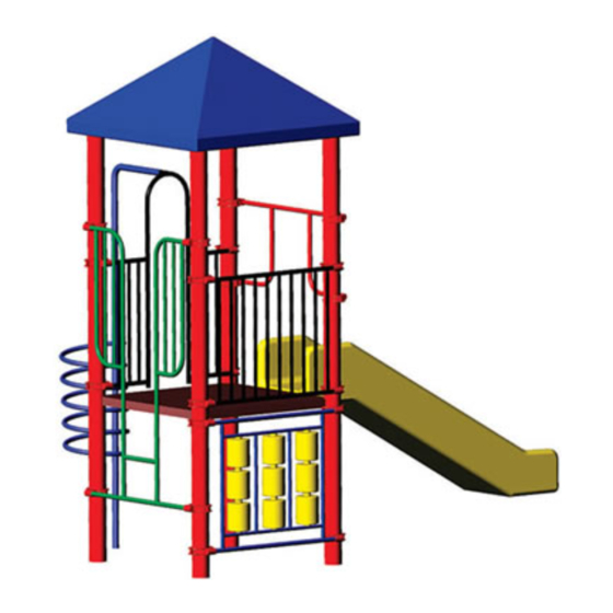
- Page 1 911-110 Model Ray 800-727-8180 www.sportsplayinc.com Page 1...
-
Page 2: Table Of Contents
Pyramid Roof 902-275 ........... 33 INDEX Pyramid Roof Plan:............. 34 Label Installation ..............35 Top of Surfacing Label ............35 INDEX ..................2 Warning Label ..............35 Tool and Material Checklist............3 Manufacturer Label............. 35 Introduction................4 Trouble Shooting ..............36 Quick Guide ................ -
Page 3: Tool And Material Checklist
• Small, skinny, flat shims are helpful in raising posts etc. 2” by 4” and 2” by 6” and Plywood are also helpful Tool and Material Checklist • Pencils and markers • String line • To dig holes, the best method is a tractor with an auger. •... -
Page 4: Introduction
BEFORE STARTING INSTALLATION OF YOUR PLAYGROUND, PLEASE READ INSTRUCTIONS All SportsPlay Equipment play events have been engineered to THOROUGHLY. meet all applicable safety guidelines, but if installed improperly, these problems may occur: SITE REQUIREMENTS: •... -
Page 5: Quick Guide
Use both to identify, inventory and best position instructions. the parts around the perimeter of the area. If you find damaged or parts missing, contact your SportsPlay Distributor BRACING – As the decks and kick plates are installed, be immediately. - Page 6 MAINTENANCE - Consult your instruction booklet for the maintenance checklist. Schedule and complete periodic maintenance checks of the entire playground. If any hardware is worn, or any item missing or broken, close the playground and contact your SportsPlay distributor for replacement parts. Page 6...
-
Page 7: Safety Surfacing/Fall Heights
Safety Surfacing/Fall Heights 1. 12” below existing grade 2. 6” below and 6” above existing grade You must consider the type of safety surfacing you will use 3. 12” above existing grade before beginning the installation process. There are two general types, organic/loose fill or synthetic unitary. - Page 8 Safety Surfacing Chart Chart taken from The Handbook for Public Playground Safety written by the U.S. Consumer Product Safety Commission Table – Critical heights (in feet) of Tested Materials (CPSC) page 5 (www.cpsc.gov). Material Uncompressed Compressed Depths Depths 6” 9” 12”...
-
Page 9: Punch List
as necessary to make the lines level. Repeat this for the Punch List remaining two posts. Step 1: Layout Step 3: Deck and Post Installation 1. Lay square deck on ground in the desired location and 1. Measure 36” plus the amount of safety surfacing you measure from all corners to insure there is adequate are planning on using (example: 36”... - Page 10 2. Next install the double wall slide per instructions on page 31. Make sure water drains out of the slide bed and the slide guard is level, then tighten. 3. Now install the Guard Wall and Wheel per instructions page 21 and 23. Level and tighten. 4.
-
Page 11: Top Down View
Top Down View Actual scale drawings are included at the end of these instructions. Page 11... -
Page 12: Footing Diagram
Footing Diagram Page 12... -
Page 13: Post Installation
• Use a marker to mark 22” from bottom of posts. Use Post Installation these marks so you can run a 4’ level across marks to make sure the tops of the posts are equal to each other. Footing size may vary due to local soil and weather conditions. If line marks are on bubble, then post tops should be on Base of footing MUST be below the frost line. - Page 14 Side view of installed post Page 14...
-
Page 15: Deck And Pipe Clamp Installation
Deck and Pipe Clamp Installation Deck Clamp 903-002 Item Part # Part Description Quantity 105-025 Clamp half FRONT 105-026 Clamp half BACK 116-600 1/2” x 2 1/2” Button Head Bolt 196-550 Roll Pin 1/4” x 1 3/4” 236-601 3/8” T-Nut 196-555 Roll Pin 1/4”... -
Page 16: Deck Clamp Plan
Deck Clamp Plan: IMPORTANT: Extra roll pins can be installed through certain high traffic clamp applications such as firepoles, roof clamps, The deck clamps connect to the main upright posts according handholds, etc. Finally smooth down any drill holes etc., with to the deck height(s) located on the Top Down View. -
Page 17: Pipe Clamp Plan
Pipe Clamp Plan: If the clamp is crooked to the pipe, and the pipe WILL NOT be able to enter the clamp. Sometimes, you can coax the clamp The pipe clamps connect to the main upright posts according to onto the pipe with a rubber hammer. If that will not work, take the height of the events found on the Top Down View. - Page 18 etc. Finally smooth down any drill holes etc., with steel wool or a file. SPECIFICATIONS: Event: Clamps shall be 606ITS aluminum fastener for 5” OD posts weighing 2.21 lbs. Paint shall be elecrtostatically applied oven cured powdercoat. Hardware: Stainless Steel tamper resistant MAINTENANCE: Touch up any marred paint surfaces.
-
Page 19: Deck Installation
Deck Installation Square Deck Item Part # Part Description Quantity 905-705 Square Deck 903-002 Deck Clamp Assembly 316-801 1/2” Washer 226-801 1/2” Lock Nut 126-703 3/8” x 1” Button Head Bolt Triangle Deck Item Part # Part Description Quantity 903-002 Deck Clamp Assembly 905-710 Triangle Deck... -
Page 20: Deck Plan
Deck Plan: Paint: Oven cured plastisol The deck(s) connect to the main upright posts according to the Hardware: Stainless Steel tamper resistant specifications found on the Top Down View. INSTRUCTIONS: MAINTENANCE: There are two methods: Touch up any marred paint surfaces. Periodically check hardware for integrity and tightness. -
Page 21: Guard Wall 902-135-W
Guard Wall 902-135-W Item Part # Part Description Quantity 913-117-W Guard Wall /fitting 903-001 Clamps 196-807 3/8” x 3/8” Socket Set Screw 196-550 1/4” x 3/4” Roll Pin 236-601 3/8” T-Nut 126-706 3/8” x 1 3/4” Button Head Bolt Page 21... -
Page 22: Guard Wall Plan
Guard Wall Plan: The 10 Rung Guard Wall attaches above the deck to the “deck side” of the posts with 4 post clamps. There is a mounting plate for the Steering Wheel that will be attached later. INSTRUCTIONS: • Install the wall on the “deck side” of the posts. •... -
Page 23: Steering Wheel 902-114
Steering Wheel 902-114 Item Part # Part Description Quantity Welded wheel fitting 905-117 Steering Wheel 902-135- Guard Wall with welded wheel fitting 116-600 1/2” x 1/2” Button Head Bolt 316-801 1/2” Flat Washer 226-802 1/2” Nylon Lock Nut Page 23... -
Page 24: Steering Wheel Plan
Steering Wheel Plan: The Steering Wheel attaches to the 10 Rung Guard Wall onto the welded bracket. INSTRUCTIONS: • Place the 1/2” lock nut INSIDE the wheel so as not to create a protrusion. • Place one washer between the bolt head and the plate •... -
Page 25: Tic Tac Toe Panel 902-121
Tic Tac Toe Panel 902-121 Item Part # Part Description Quantity 903-121 Tic Tac Toe Panel 903-001 Post Clamp 196-807 3/8” x 3/8” Socket Set Screw 196-555 1/4” x 3/4” Roll Pin 236-601 3/8” T Nut 126-706 3/8” x 1 3/4” Button head bolt Page 25... -
Page 26: Tic Tac Toe Panel Plan
Tic Tac Toe Panel Plan: The Tic Tac Toe Panel attaches above or below the deck to the “deck side” of the posts with 4 post clamps. See 2d Top Down view for proper placement. INSTRUCTIONS: • Install the wall on the “deck side” of the posts •... -
Page 27: Vertical Climber
Vertical Climber Item Part # Part Description Quantity 902-125-3 Vertical Climber with barrier 902-125-4 902-125-5 902-125-6 902-127 Vertical Climber for overheads 903-001 Pipe Clamp 196-550 1/4” x 1/4” roll pin 196-807 Socket Set Screw 236-601 3/8” T-Nut 126-706 3/8” x 1 3/4” Button head bolt Page 27... -
Page 28: Vertical Climber Plan
Vertical Climber Plan: Page 28... -
Page 29: Corkscrew Climber 902-133-3, -4, -5
Corkscrew Climber 902-133-3, -4, -5 Item Part # Part Description Quantity 903-137 Arch Wall 903-133-3 Corkscrew Climber 3’ 903-133-4 Corkscrew Climber 4’ 903-133-5 Corkscrew Climber 5’ 903-001 Pipe Clamp 196-555 1/4” x 3/4” Roll Pin 196-807 3/8” x 3/8” Socket Set Screw 236-601 3/8”... -
Page 30: Corkscrew Climber Plan
Corkscrew Climber Plan: The Corkscrew Climber attaches to the deck from an arch wall. INSTRUCTIONS: • Install the arch wall on the “deck side” of the posts with pole attachment stub facing outward. • Attach the Corkscrew Climber to the arch wall. (See detail C) Be sure to maintain the same width between the top and bottom of the arch entry opening. -
Page 31: Double Wall Straight Slide 902-213, 4, 5
Double Wall Straight Slide 902-213, 4, 5 Item Part # Part Description Quantity 902-213 Double Wall Straight Slide 3’ 902-214 Double Wall Straight Slide 4’ 902-215 Double Wall Straight Slide 5’ 913-115 Slide Guard 903-214 Slide Leg 903-001 Pipe Clamp 903-213 Z Plate (installed on slide) 126-701... -
Page 32: Double Wall Straight Slide Plan
Double Wall Straight Slide Plan: SPECIFICATIONS: The Double Wall Straight Slide attaches to the deck by bolting Event: Double Wall Straight Slide is 3/8” wall, rotationally through the Z plate and the deck sidewall. See the Top Down molded, 24” wide slide bed with 6” high side rails. Metal View for placement. -
Page 33: Pyramid Roof 902-275
Pyramid Roof 902-275 Item Part # Part Description Quantity 902-275 Pyramid Roof 905-435 Roof Bracket 516-200 3/8” Zip Toggle 316-601 3/8” Flat Washer 126-705 3/8” x 2” Button head bolt 196-807 3/8” x 3/8” Socket Set Screw Page 33... -
Page 34: Pyramid Roof Plan
Pyramid Roof Plan: Touch up any marred paint surfaces. Roofs are attached to brackets that sleeve over four upright Periodically check hardware for integrity and tightness. posts. See the Top Down View for placement. INSTRUCTIONS: • Attach roof to posts by placing the roof brackets over each post. -
Page 35: Label Installation
Install them where they will not be disturbed during play. Inspect labels regularly. If torn, disfigured, damaged or faded, contact your SportsPlay distributor for replacement labels. Top of Surfacing Label Install one to each upright post at the level you have determined will be your “Top of Surfacing”... -
Page 36: Trouble Shooting
Problem: There is interference between a vertical portion of Trouble Shooting one component and another vertical portion of another component going into the opposite direction. (For instance, in Problem: Incorrect sized hole or no hole where there is the case of a tunnel or bubble window that has a vertical spacer supposed to be one. -
Page 37: Safety Checklist
• Roll pins; make sure they are flush and to not stick out. Safety Checklist • Clamps, when aluminum is hammered, it can cause a rough area. De-burr if necessary. Carefully go over each post, deck and component with bare •... -
Page 38: Photo Appendix
Photo Appendix Explosion drawings are included throughout the instructions. Photographs have been included for those who prefer them. 1. Mark post hole positions 2. Install post 3. Install deck 4. Install deck clamp 5. Install pipe clamp 6. Install panel (slide guard/arch wall/etc.) to pipe clamp 7. - Page 39 Page 39...
- Page 40 Page 40...
-
Page 41: Maintenance Checklist
Maintenance Checklist LOCATION______________________ INSPECTOR_____________________ DATE___________________________ INSTRUCTIONS: All playground components are listed below. Check monthly. Train personnel (through study of CPSC Guidelines and ASTM standards) to be alert to playground hazards and report them promptly. Avoid use of hazardous equipment until repaired. Check in equipment column means satisfactory.
Need help?
Do you have a question about the Ray 911-110 and is the answer not in the manual?
Questions and answers