Page 1
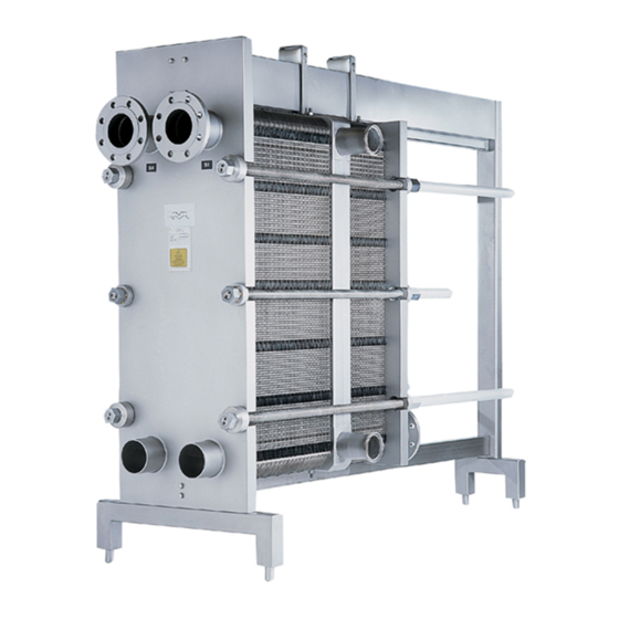
Gasketed plate-and-frame heat exchangers ® BaseLine M line Instruction Manual Lit. Code 200000423-1-EN-GB...
Page 2
Alfa Laval Corporate AB 2019-01 This document and its contents is owned by Alfa Laval Corporate AB and protected by laws governing intellectual property and thereto related rights. It is the responsibility of the user of this document to comply with all applicable intellectual property laws. Without limiting any rights related to this document, no part of this document may be copied, reproduced or transmitted in any form or by any means (electronic, mechanical, photocopying, recording, or otherwise), or for any purpose, without the expressed permission or authorized by Alfa Laval Corporate AB.
Page 3
English Magyar Download local language versions of this instruction Az Ön nyelvére lefordított használati útmutatót manual from www.alfalaval.com/gphe-manuals or use letöltheti a www.alfalaval.com/gphe-manuals the QR code weboldalról, vagy használja a QR-kódot. български Italiano Изтеглете версиите на това ръководство за Scarica la versione in lingua locale del manuale di употреба...
Page 4
Pусский Руководство пользователя на другом языке вы можете загрузить по ссылке www.alfalaval.com/ gphe-manuals или отсканировав QR-код. Slovenski Prenesite različice uporabniškega priročnika v svojem jeziku s spletne strani www.alfalaval.com/gphe- manuals ali uporabite kodo QR. Slovenský Miestne jazykové verzie tohto návodu na používanie si stiahnite z www.alfalaval.com/gphe-manuals alebo použite QR kód.
Maintenance and installation of the heat exchanger shall be done by persons who have knowledge and authorization according to local regulations. This may include actions such as piping, welding and other kind of maintenance. For maintenance actions not described in this manual, contact your Alfa Laval representative for advice. PHE drawings PHE (plate heat exchanger) drawings mentioned in the manual are the drawings included in the delivery of the heat exchanger.
1.2 Environmental compliance Alfa Laval endeavours to perform its own operations as cleanly and efficiently as possible, and to take environmental aspects into consideration when developing, designing, manufacturing, servicing and marketing its products.
Laval’s instructions in this manual. Incorrect handling of the heat exchanger may result in serious consequences with injuries to persons and/or property damage. Alfa Laval will not accept responsibility for any damage or injury resulting from not following the instructions in this manual.
3 Description 3.1 Components Main components 1. Frame plate Fixed plate with a various number of portholes for the connection of the piping system. The carrying and guiding bar are attached to the frame plate. 2. Carrying bar Carries the plate pack and the pressure plate. 3.
Page 12
3 Description Multi-section and multi-pass • Connection plate Plate used to separate two or more services in one heat exchanger. The plate pack performing such a service is called a section. • Corners The connection plates can be configured by selecting different corner connections such as single, double, pass-through or blind.
Description 3 3.2 Name plate The type of unit, manufacturing number and manufacturing year can be found on the name plate. Pressure vessel details in accordance with the applicable pressure vessel code are also given. The name plate is fixed to the frame plate, most commonly, or the pressure plate.
Page 14
3 Description Manufacturer Type Serial No. MANUFACTURER: Year YEAR OF MANUFACTURING: Fluid group TYPE: SERIAL NUMBER: Inlet Outlet Volume → → Allowable press. INLET → OUTLET Min./Max. FLUID GROUP VOLUME Allowable temp. MAX. OP. TEMP. Min./Max. TS ALLOWABLE PRESS. Manufacturer MIN./MAX.
Description 3 3.3 Function The heat exchanger consists of a pack of corrugated metal plates with portholes for the input and output of the two separate fluids. The heat transfer between the two fluids takes place through the plates. The plate pack is assembled between a frame plate and a pressure plate and compressed by tightening bolts.
3 Description 3.4 Multi-section A multi-section heat exchanger can be set up by using connection plates. An example of multi-section configuration is when a media needs to be heated in one stage and then cooled down in the next stage. Each of the connection plates can be configured by selecting different corner connections such as single, double, pass-through or blind.
Description 3 3.5 Multi-pass Multi-pass sections can be created by using turning plates with 1, 2 or 3 unholed ports. The main purpose is to change the flow direction of one or both fluids. For some units, a partition plate is required to support the unholed ports in the turning plates.
4 Installation 4.1 Before installation To consider before installation • Before connecting any piping, make sure all foreign objects have been flushed out of the piping system that should be connected to the heat exchanger. • Before start-up, check that all the tightening bolts are firmly tightened and that the plate pack has the correct measurements.
4 Installation 4.2 Requirements Space Please refer to the delivered PHE drawing for actual measurements. 1. Free space is required for lifting plates in and out. 2. Free space is required under the lower tightening/locking bolt for maintenance. 3. Supports for the guiding bar may be needed. 4.
Page 21
Installation 4 CAUTION Turning of the connections will damage the gaskets on the end plate and cause leakage. Fit the pipes so that no tension is transferred to the heat exhanger. Nozzle loads are not permitted. Pipes connected to the pressure plate and to the connection plates must allow ±1% of the distance from the connection to the frame plate (see the assembly PHE drawing).
Use of other attachment points or strap load directions than those described are not allowed. If the heat exchanger is not supplied with lifting devices from Alfa Laval, the corresponding equipment must be selected and the same attachment points must be used.
Installation 4 4.4 Raising This instruction is valid when raising the heat exchanger after delivery from Alfa Laval. Only use a strap approved for the weight of the heat exchanger. Follow the principle of the instruction below. CAUTION The straps shall be long enough to be able to rotate the heat exchanger without obstruction.
Page 24
4 Installation Lift the heat exchanger off the timber beams. Lower the heat exchanger into a horizontal position and place it on the floor. 200000423-1-EN-GB...
5 Operation 5.1 Start-up During the start-up, check that there are no visible leakages from the plate pack, valves or piping system. CAUTION Before pressurizing the heat exchanger, it is important to ensure that the temperature of the heat exchanger is within the temperature range as stated on the name plate. CAUTION If the temperature of the heat exchanger is below the minimum temperature for the gaskets prior to the service, it is recommended to heat the heat exchanger above this limit to avoid cold...
Page 26
5 Operation Check that the valve is closed between the pump and the unit controlling the system flow rate to avoid pressure surge. If there is a vent valve installed at the exit, make sure it is fully open. Increase the flow rate slowly. Open the air vent and start the pump.
Operation 5 5.2 Unit in operation Adjustments of flow rates should be made slowly in order to protect the system against sudden and extreme variations of temperature and pressure. During operation, check that media temperatures and pressures are within the limits stated on the name plate and the PHE drawing.
29 and Cleaning – Non-product side on page 32) or reconditioning can be performed at an Alfa Laval service center. After a long period of use, it can be required to regasket the heat exchanger. Refer to Regasketing on page 42.
Page 30
20°C. Treat for five minutes, up to maximum of 15 minutes. Rinse well after sterilisation. Typical cleaning programs Consult your local Alfa Laval representative for advice on suitable cleaning programmes. Table 1: Coolers Products rich in protein...
Page 31
Maintenance 6 Products rich in protein Daily Weekly Rinsing 10 min Rinsing 5 min Stop Lye 20 min Sterilisation 10 min Rinsing 10 min Stop Sterilisation Table 2: Pasteurisers and other heaters Products rich in protein Daily Rinsing 5 min Acid 15 min Rinsing 5 min Lye 20 min...
Use proper protective equipment, such as safety boots, safety gloves and eye protection, when using the cleaning agents. WARNING Corrosive cleaning liquids. Can cause serious injuries to skin and eyes! CIP equipment Contact an Alfa Laval sales representative for the size of CIP equipment. 200000423-1-EN-GB...
Page 33
Maintenance 6 WARNING The residuals after a cleaning procedure shall be handled according to local environmental regulations. After neutralization most cleaning solutions may be drained into the waste water system under the condition that the fouling deposits do not contain heavy metals or other toxic or environmentally dangerous compounds.
During manual cleaning, it is necessary to open the heat exchanger to clean the plates. NOTE Before opening the heat exchanger, check the warranty conditions. If in any doubt, contact the Alfa Laval sales representative. Refer to Warranty conditions on page 7.
Maintenance 6 6.3.2 Opening procedure Shut down the heat exchanger. Close the valves and isolate the heat exchanger from the rest of the system. Drain the heat exchanger. NOTE Avoid vacuum in the heat exchanger by opening vent valves. Remove the protection sheets, if any. Dismantle pipes from the pressure plate and the connection plate(s) so that the pressure plate and the connection plate(s) are free to...
Page 36
6 Maintenance Mark the plate assembly on the outside by a diagonal line. Measure and note the dimension. Loosen and remove the locking bolts. Identify them according to Bolt configuration on page NOTE Brush the threads of the tightening bolts with a steel wire brush and then grease the threads before loosening the tightening bolts.
Maintenance 6 CAUTION To avoid hand injuries owing to sharp edges, protective gloves should always be worn when handling plates and protection sheets. Open the plate pack by letting the pressure plate glide on the carrying bar. If plates are to be numbered, do this before removing the plates.
6 Maintenance WARNING Use proper protective equipment, such as safety boots, safety gloves and eye protection, when using the cleaning agents. WARNING Corrosive cleaning liquids. Can cause serious injuries to skin and eyes! 6.4.1 Deposits removable with water and brush Plates do not need to be removed from the heat exchanger during cleaning.
Check that the hanger device is not damaged. Brush the threads of the bolts clean, using a steel wire brush or the Alfa Laval thread cleaner. Lubricate the threads with a thin layer of grease, e.g. Gleitmo 800 or its equivalent.
Page 40
6 Maintenance If the plates have been removed, insert them in alternate directions and with the gaskets turned towards the frame plate or pressure plate as specified on the plate hanging list. Use the marked line that was made when the heat exchanger was opened, refer to step on page 36 in Opening...
Maintenance 6 Tighten the four bolts (1), (2), (3), (4) evenly until dimension A has been reached. When a pneumatic tightening device is used, see table below for maximum torque. Measure dimension A during tightening. Bolt with bearing Bolt with washer Bolt size 13.5 17.5...
Example of a rebuilding is that more number of plates are added to the plate pack. If there is any uncertainty about the testing procedure of the heat exchanger, consult an Alfa Laval representative. 6.7 Regasketing The procedures below concern field gaskets, ring gaskets and end gaskets.
Open the heat exchanger, refer to Opening on page 34. NOTE Before opening the heat exchanger, check the warranty conditions. If in any doubt, contact the Alfa Laval sales representative. Refer to Warranty conditions on page 7. Remove the old gasket with the plate still hanging in the frame.
Page 45
7 Storage of the heat exchanger Alfa Laval delivers the heat exchanger ready to be put into service upon arrival, if nothing else has been agreed. Nevertheless, keep the heat exchanger in the packing box until installation. If storing for longer periods of time, such as one month or longer, certain precautions should be made to avoid unnecessary damage to the heat exchanger.
Page 46
Closing on page 39. 7. Alfa Laval recommends a hydraulic test should be carried out. The media, usually water, should be entered at intervals to avoid sudden shocks to the heat exchanger. It is recommended to test up to the Design Pressure.
Need help?
Do you have a question about the BaseLine M and is the answer not in the manual?
Questions and answers