
Related Manuals for Alfa Laval M3


Summary of Contents for Alfa Laval M3
- Page 1 Instruction Manual - Plate Heat Exchangers M3, M6, M10, TS6, T2, T5, T8, TL3, TL6 3490010216-EN 2016-06 Original manual...
-
Page 3: Table Of Contents
(electronic, mechanical, photocopying, recording, or otherwise), or for any purpose, without the expressed permission of Alfa Laval Corporate AB. Alfa Laval Corporate AB will enforce its rights related to this document to the fullest extent of the law, including the seeking of criminal prosecution. -
Page 4: Preface
Storage of the heat exchanger regarding media type, pressures, temperatures in the heat Alfa Laval delivers the heat exchanger ready to be put exchanger as well as specific precautions required by the into service upon arrival, if nothing else has been agreed. -
Page 5: Storage In Packing Box
If storage of the heat exchanger after delivery is known it is recommended to let the gasket rubber rest to regain in advance, inform Alfa Laval when ordering the heat most of its elasticity. exchanger to ensure that it will be properly prepared for 1. -
Page 6: Description
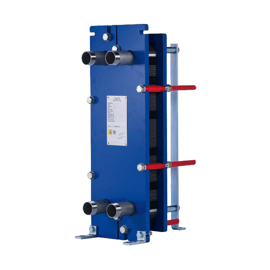
Description Description Components Main components Frame plate Fixed plate with a various number of portholes for the connection of the piping system. The carrying and guiding bar are attached to the frame plate. Carrying bar Carries the plate pack and the pressure plate. Plate pack Heat is transferred from one media to the other through the plates. - Page 7 Threaded stud bolts around the portholes secure the flange connections to the apparatus. Squared loose flange The squared loose flange is a special flange supplied by Alfa Laval to be used with the customers piping and is attached with four stud bolts.
-
Page 8: Name Plate
Description Name plate The type of unit, manufacturing number and manufacturing year can be found on the name plate. Pressure vessel details in accordance with the applicable pressure vessel code are also given. The name plate is fixed to the frame plate, most commonly, or the pressure plate. The name plate can be a steel plate or a sticker label. -
Page 9: Function
Description Function The heat exchanger consists of a pack of corrugated metal plates with portholes for the input and output of the two separate fluids. The heat transfer between the two fluids takes place through the plates. The plate pack is assembled between a frame plate and a pressure plate and compressed by tightening bolts. -
Page 10: Multi-Pass
Description Multi-pass Multi-pass sections can be created by using turning plates with 1, 2 or 3 unholed ports. The main purpose is to change the flow direction of one or both fluids. For some units, a partition plate is required to support the unholed ports in the turning plates. A transition plate also needs to be added to the pack to prevent media from coming into contact with the partition plate or pressure plate. -
Page 11: Installation
Installation Installation Before installation To consider before installation • Before connecting any piping, make sure all foreign objects have been flushed out of the piping system that should be connected to the heat exchanger. • Before start-up, check that all the tightening bolts are firmly tightened and that the plate pack has the correct measurements. - Page 12 Installation Elbow To make it easier to disconnect the heat exchanger, an elbow should be fitted to the connection in the pressure plate, directed upwards or sideways, and with another flange located just outside the contour of the heat exchanger. Shut-off valve To be able to open the heat exchanger, shut-off valves should be provided in all connections.
-
Page 13: Lifting
Never lift by the connections or the studs around them. Figure 4. Lifting TS6 Raising This instruction is valid when raising the heat exchanger after delivery from Alfa Laval. Only use a strap approved for the weight of the heat exchanger. Follow the principle of the instruction below. - Page 14 Installation Step 2 Lift the heat exchanger off the pallet using e.g. straps. Step 3 Place the heat exchanger on the timber beams. Step 4 Place straps around one bolt on each side. Step 5 Lift the heat exchanger off the timber beams. Step 6 Lower the heat exchanger into a horizontal position and place it on the floor.
-
Page 15: Operation
Operation Operation Start-up During the start-up, check that there are no visible leakages from the plate pack, valves or piping system. Caution! Before pressurizing the heat exchanger, it is important to ensure that the temperature of the heat exchanger is within the temperature range as stated in the PHE drawing. Caution! If the temperature of the heat exchanger is below the minimum temperature for the gaskets prior to the service, it is recommended to heat the heat exchanger above this... - Page 16 Operation Step 3 If there is a vent valve installed at the exit, make sure it is fully open. Step 4 Increase the flow rate slowly. Step 5 Open the air vent and start the pump. Step 6 Open the valve slowly. Note! Avoid rapid temperature changes in the heat exchanger.
-
Page 17: Unit In Operation
Operation Unit in operation Adjustments of flow rates should be made slowly in order to protect the system against sudden and extreme variations of temperature and pressure. During operation, check that media temperatures and pressures are within the limits stated on the name plate and the PHE drawing. -
Page 18: Maintenance
Warning! Corrosive cleaning liquids. Can cause serious injuries to skin and eyes! CIP equipment Contact an Alfa Laval sales representative for the size of CIP equipment. Caution! The residuals after a cleaning procedure shall be handled according to local environmental regulations. After neutralization most cleaning solutions may be drained into the waste water system under the condition that the fouling deposits do not contain heavy metals or other toxic or environmentally dangerous compounds. - Page 19 Maintenance Cleaning liquids Liquid Description AlfaCaus A strong alkaline liquid, for removing paint, fat, oil and biological deposits. AlfaPhos An acid cleaning liquid for removing metallic oxides, rust, lime and other inorganic scale. Contains repassivation inhibitor AlfaNeutra A strong alkaline liquid for neutralization of AlfaPhos before drainage.
-
Page 20: Opening
Note! Before opening the heat exchanger, check the warranty conditions. If in any doubt, contact the Alfa Laval sales representative. Refer to “Warranty conditions” on page 4 . Warning! If the heat exchanger is hot, wait until it has cooled down to about 40°C (104°F). - Page 21 Maintenance Step 3 Drain the heat exchanger. Note! Avoid vacuum in the heat exchanger by opening the vent valves. Step 4 Remove the protection sheets, if any. Step 5 Dismantle pipes from the pressure plate so that the pressure plate are free to move along the carrying bar. Step 6 Inspect the sliding surfaces of the carrying bar and wipe clean and grease.
- Page 22 Maintenance Step 9 Loosen and remove the locking bolts. Identify them according to “Bolt configuration” on page 20. Note! Brush the threads of the tightening bolts with a steel wire brush and then grease the threads before loosening the tigthening bolts. Step 10 Use the tightening bolts to open the heat exchanger.
- Page 23 Caution! When opening the plate pack of the models M3, T2 and TL3, be careful when moving the pressure plate. Make sure the pressure plate is positioned safely from the end of the carrying bar.
-
Page 24: Manual Cleaning Of Opened Units
Maintenance Manual cleaning of opened units Caution! Never use hydrochloric acid with stainless steel plates. Water of more than 330 ppm Cl may not be used in the preparation of cleaning solutions. It is very important that aluminium carrying bars and support columns are protected against chemicals. - Page 25 Maintenance Deposits not removable with water and brush Plates must be removed from the heat exchanger during cleaning. For a choice of cleaning agents, refer to “Cleaning liquids” on page 19. Step 1 Brush with cleaning agent. Step 2 Rinse immediately with water. Note! Long exposure to the cleaning agents can damage the gasket glue.
-
Page 26: Closing
Check that all the sealing surfaces are clean. Step 2 Brush the threads of the bolts clean, using a steel wire brush or the Alfa Laval thread cleaner. Lubricate the threads with a thin layer of grease, e.g. Gleitmo 800 or its equivalent. Step 3 Attach the gaskets to the plates or check that all gaskets are properly attached. - Page 27 Maintenance Step 6 Press the plate pack together. Position the four tightening bolts according to the figure. Tighten the four bolts (1), (2), (3), (4) until the plate pack measure A is 1.10 making sure the frame plate and pressure plate are parallel when closing.
-
Page 28: Pressure Test After Maintenance
The recommended test time is 10 minutes for each media. Consult your local Alfa Laval representative for advice on the pressure testing procedure. Document ID... -
Page 29: Regasketing
Note! Before opening the heat exchanger, check the warranty conditions. If in any doubt, contact the Alfa Laval sales representative. Refer to “Warranty conditions” on page Step 2 Remove the old gasket. - Page 30 Maintenance Glued gaskets Use glue recommended by Alfa Laval. Separate gluing instructions will be delivered together with the glue. Caution! Other glues than those recommended can contain chlorides that can damage the plates. Warning! Do not use sharp tools when removing the glued gasket to avoid damage to the plates.
Need help?
Do you have a question about the M3 and is the answer not in the manual?
Questions and answers