
Related Manuals for Alfa Laval MBPX404


Summary of Contents for Alfa Laval MBPX404
- Page 1 Alfa Laval Separation System MBPX404 Installation and Operating Lit. Code 200007139-3-EN-GB Manual No. 9662082640 instructions BRITISH ENGLISH...
- Page 2 © Alfa Laval Corporate AB 2022-11 This document and its contents are subject to copyrights and other intellectual property rights owned by Alfa Laval Corporate AB. No part of this document may be copied, re-produced or transmitted in any form or by any means, or for any purpose, without Alfa Laval Corporate AB’s prior express written permission. Information and services provided in this document are made as a benefit and service to the user, and no representations or warranties are made about the accuracy or suitability of this information and these services for any purpose.
-
Page 3: Table Of Contents
1 Introduction and General Information ............5 Scope of this book.....................5 Safety Instructions.....................6 General description of Alfa Laval Separation System..........11 MBPX404 System description................. 11 2 Installation, Maintenance and Lifting Instructions ......15 Unpacking and Initial Inspection of the Separator...........15 Lifting instructions....................18... - Page 4 6.11 Discharge performance and Bowl closing supervision..........47 6.12 Bowl speed control....................48 7 Alarm Management ....................49 Alarm acknowledgement..................49 Alarm activation diagram..................50 8 Installation and Setup information .............. 53 VFD Parameters......................53 Speed converter settings..................54 Passwords.......................54 9 Ordering Spare parts ................... 55 Spare parts......................55 Alfa Laval Service....................55...
-
Page 5: Introduction And General Information
1 Introduction and General Information 1.1 Scope of this book The Installation and Operating instructions given in this manual are designed for the Alfa Laval separation system with valve arrangement and Siemens PLC automation. In this manual you will find: •... -
Page 6: Safety Instructions
Alfa Laval will not be responsible for any breakdown of the equipment caused by the owner’s failure to follow the instructions given in this documentation. This documen- tation describes the authorized way to use the separator system. - Page 7 Repairs: unscheduled break-down of a component, often causing the system to stop. Damaged components shall be replaced or repaired. • Stock of recommended spare parts: Alfa Laval recommends keeping a stock of spare parts facilitating preventive maintenance and reducing the system down time in case of unplanned bread downs.
- Page 8 Safety Stop • After a safety stop the cause of the fault must be identified. If all parts have been checked and the cause remains unclear, contact Alfa Laval for advice. Vibration • If the separator begins to vibrate excessively during operation, stop it immediately by pushing the emergency stop button and evacuate the room.
- Page 9 Introduction and General Information 1 Hazards Hazardous Area • Cleaning, maintenance and repair work may be done only at nonexplosive atmos- phere. • The separator may be hazardous when passing its critical speeds during the run- down. • For reasons of safety, only tools made of non-sparking material may be used when performing work in hazardous area.
- Page 10 1 Introduction and General Information Corrosion Hazard • Always handle cleaning liquids, lye and acid with great care and in accordance with separate instructions for those fluids. • When using chemical cleaning agents and lubricants, make sure you follow the general rules and suppliers recommendation regarding ventilation, personnel pro- tection etc.
-
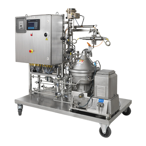
Page 11: General Description Of Alfa Laval Separation System
Introduction and General Information 1 1.3 General description of Alfa Laval Separation System The separation system is designed for clarification purposes in biotech applications. It is a system with product and utility line, valve arrangement, and automation with control panel. - Page 12 1 Introduction and General Information Process/service liquid module The process liquid components are used for flow control through the separator. There is an inlet for process liquid (201.1). There is also an outlet for the clarified liquid (centrifugate) (220.1) The concentrate is pumped out through the concentrate outlet (222.1). The service liquid components supply service liquid to the separator.
- Page 13 Introduction and General Information 1 Electrical and Control system The system consists of the control panel with the pneumatic unit and a variable frequency drive (VFD) for the separator. The pneumatic equipment distributes instrument air (502) to the pneumatic valves and for pressurizing purposes.. The control equipment controls and supervises the entire system and gives alarms and actions if anything goes wrong.
- Page 14 1 Introduction and General Information 200007139-3-EN-GB...
-
Page 15: Installation, Maintenance And Lifting Instructions
2 Installation, Maintenance and Lifting Instructions NOTE For installation and maintenance of the separator, refer to the instructions in the separator documentation. NOTE For installation and maintenance of equipment, refer to the supplier documentation provided in section 4 and 5 of the turnover package. 2.1 Unpacking and Initial Inspection of the Separator THIS WAY UP Position: Near left hand upper corner... - Page 16 • If during the inspection of the delivered components there are found damaged or missing items, it shall be reported to Alfa Laval immediately after the delivery has taken place. • Alfa Laval can instruct how to repair possible damages or how to replace missing items.
- Page 17 Installation, Maintenance and Lifting Instructions 2 Storage Before storing a separator that has been in operation, make sure to drain any parts containing water, such as Operating water module (if any), Operating water system and Cooling jackets. Upon arrival to the store, check all components and keep them: •...
-
Page 18: Lifting Instructions
2.2 Lifting instructions NOTE Always refer to the layout drawing and lifting drawing for overall dimensions, weight and connection points (as per scope of supply from Alfa Laval). NOTE When lifting a separator, always follow the instructions from the separator’s installation manual. -
Page 19: Mechanical Installation And Maintenance
2.3 Mechanical installation and maintenance The separation system should be placed in such a way that suitable space for maintenance and repair is obtained. Always contact local Alfa Laval representative for a guidance on the installation details. Mechanical installation work should always be performed by authorized personnel and according to local legislation. -
Page 20: Electrical Installation And Maintenance
2 Installation, Maintenance and Lifting Instructions 2.4 Electrical installation and maintenance Always refer to the electrical drawings provided with the system before carrying out electrical installation. Electrical installation work must always be performed by authorized electricians and personnel, and should be done according to local legislation. The dimensions of the control cabinet and cables can be found in the electrical drawing for the system. -
Page 21: Cleaning
Clean all parts of the remains of product and contamination. Do not scratch or damage parts during cleaning. Use only Alfa Laval recommended CIP liquids. The plant operator is responsible for selecting the cleaning material and performing the procedure. -
Page 22: Installation Of Auxiliary Equipment
2 Installation, Maintenance and Lifting Instructions 2.6 Installation of Auxiliary Equipment Below are the general check points of installation of auxiliary equipment such as valve modules and electric/pneumatic units. • Fasten valve modules such as process liquid module or service liquid unit with bolts of high strength material to the foundation. -
Page 23: Start-Up And Commissioning
3 Start-Up and Commissioning 3.1 Before Start-Up and Commissioning Before commissioning or start-up of the system can be initiated, the following two conditions should be fulfilled: • OWMC service to be done before separator commissioning according to instructions in the “Service & maintenance manual” of separator. •... -
Page 24: Completion And Start-Up
3 Start-Up and Commissioning 3.2 Completion and Start-Up • For general start-up of the module please refer to the “Operation Instructions” of the documentation and check below points: • Check that all pipe connections have been made according to the supplied drawings and documentation. -
Page 25: Description Of Operating Conditions
4 Description of operating conditions 4.1 MAIN SEQUENCE The software has been specially developed to operate the system to always provide the best possible performance, flexibility and a safe operation. The control program has many features and the main operating modes and options are described below. -
Page 26: Standby
4 Description of operating conditions Stop the separator during START by selecting STOP. When the pre-selected bowl speed has been reached the system changes automatically over to STANDBY. 4.4 STANDBY In STANDBY mode the separator is running at full selected speed. The separator is in waiting mode and there is no production. -
Page 27: Emergency Stop
Description of operating conditions 4 4.8 EMERGENCY STOP If you push the emergency stop button the system will switch to EMERGENCY STOP mode. This means that the control power for all motor contactors is deactivated. All other equipment is controlled as in normal STOP mode. The alarm A42 Emergency stop activated is given. - Page 28 4 Description of operating conditions 200007139-3-EN-GB...
-
Page 29: Operating Routine
5 Operating routine NOTE Make sure that the separator is assembled correctly. Always consult the Installation manual of the separator. NOTE Make sure that all electrical and liquid connections are made correctly according to the electrical drawing and the connection list, and that all couplings are tightened. NOTE Make sure that the separator control system is activated. -
Page 30: Start
5 Operating routine 5.2 START START can be selected from STAND STILL or STOP. Make sure that cooling liquid and purified water is available. Check that no alarm override functions are activated. Select START on the operator panel. The system indicates STARTING and the power to the separator motor is on and it begins to run. -
Page 31: Standby
Operating routine 5 5.3 STANDBY In STANDBY it is possible to initiate a solids discharge manually: Check that the sampling valves V201-1, V220-1 and V222-1 are closed. Select Discharge on the operator panel. NOTE Overheating hazard Overheating hazard The system should not be left in STANDBY for too long time. Changeover to PRODUCTION as soon as possible. -
Page 32: Production
5 Operating routine 5.4 PRODUCTION PRODUCTION can be selected from STANDBY. The feed flow rate is regulated according to a pre-determined set point (see Flow control). The back pressure in the centrifugate outlet is regulated according to a predetermined set point (see Backpressure control). -
Page 33: Cip
Operating routine 5 5.5 CIP CIP can be selected from STANDBY. The feed flow rate is regulated according to a pre-determined set point (see Flow control). The back pressure in the centrifugate outlet is regulated according to a predetermined set point (see Backpressure control). -
Page 34: Stop
5 Operating routine 5.6 STOP STOP can be selected from START or STANDBY. Select STOP on the operator panel. The display indicates STOP. The separator motor is turned off. When the separator bowl has come to stand still the system switches over to STAND STILL. -
Page 35: Emergency Stop
Operating routine 5 5.7 EMERGENCY STOP EMERGENCY STOP can be selected from all modes except SAFETY STOP. Push the EMERGENCY STOP button. An alarm is given and is displayed on the alarm screen. The separator motor and pumps are turned off. All other equipment is activated as in normal STOP mode. - Page 36 5 Operating routine 200007139-3-EN-GB...
-
Page 37: The Control System And Function Description
In the following section the operator interface and the control and supervision functions of the system are described. 6.1 Process screen The top header of the screen contains: • Alfa Laval logo • Information about the logged in user • Current operation mode • Time/date The second row contains: •... -
Page 38: Parameters
6 The Control system and Function description 6.2 Parameters Parameter settings gives functionality to set different set points within minimum and maximum allowed values for each parameter. The process parameters shows all process parameters including unit, minimum and maximum values. The system parameters shows all system parameters including unit, minimum and maximum values Some of the parameter settings are system specific and should not be... - Page 39 The Control system and Function description 6 6.3 I/O On the I/O screen it is possible see the status of all digital in/out and analog in/out addresses in the system (refer to the I/O-list in the technical documentation). 200007139-3-EN-GB...
-
Page 40: Discharge Logic
6 The Control system and Function description 6.4 Discharge logic This screen is used to set the discharge time interval and volume discharge set point. In operation modes with discharge initiation by time, only the field with discharge interval time is displayed. The discharge time intervals are set by P101 and P176. -
Page 41: System
The Control system and Function description 6 6.5 System The system screen displays system information such as PLC program number, version and date. On system access level it is possible to define or change new users and the passwords on the different levels. In this screen it is possible to access the Alarm list and Alarm history, to clear the Alarm history. -
Page 42: Current Log
6 The Control system and Function description 6.6 Current log This screen indicates the ten last current peaks during a discharge cycle. The size of current increase after the latest discharge can be inspected. 200007139-3-EN-GB... -
Page 43: Trend
The Control system and Function description 6 6.7 Trend On the Trend screen, and on certain screens the where the Show Trend button is available and clicked, diagrams like the following will be displayed: Diagrams can be displayed for: • Current / Speed trend •... -
Page 44: Flow Control
6 The Control system and Function description 6.8 Flow control The controller screens display the control function for the feed flow rate and allow the adjustment of some values. They can be accessed via the PID tab. The flow can be controlled by either valve FCV201–1 or feed pump, by changing the value of P125. -
Page 45: Backpressure Control
The Control system and Function description 6 6.9 Backpressure control This screen displays the controller function for the backpressure in the centrifugate outlet and allows the adjustment of some values. It can be accessed via the PID tab. The actual backpressure set point in auto-mode (SP), the actual pressure received from PIT220-1 (PV) and the actual valve opening degree for PCV220–1 in % (CV) are displayed both as bar-graphs and numerical values. -
Page 46: Output Test
6 The Control system and Function description 6.10 Output test The output test makes it possible to change the status of most of the system output signals one at a time for testing purpose (see the I/O-list in technical documentation). Select manual mode on the screen. -
Page 47: Discharge Performance And Bowl Closing Supervision
The Control system and Function description 6 6.11 Discharge performance and Bowl closing supervision A current monitor for supervision of the discharge performance and that the bowl is not leaking is included in the control equipment. The power consumption characteristics of the separator motor changes when sediment is discharged from the bowl periphery. -
Page 48: Bowl Speed Control
6 The Control system and Function description 6.12 Bowl speed control NOTE For detailed information about the speed control, please refer to the Speed control section in the SDS. The control system uses the parameter for the bowl speed to be reached (see below for different operation modes) to calculate a control value which is transmitted to the VFD. -
Page 49: Alarm Management
7 Alarm Management The separator and the auxiliary equipment are supervised by the control system. If one of the system components does not function as assigned, an alarm is given and in some cases action is required. 7.1 Alarm acknowledgement New alarm You are alerted to the new alarm by the alarm lamp flashing on the control panel, and an optical or acoustical signal (if connected, normally supplied by... -
Page 50: Alarm Activation Diagram
7 Alarm Management Alarm history Alarm history screen displays the latest 100 alarms. Selecting the Alarm history on the System tab gives access to the alarm history list. 7.2 Alarm activation diagram How to read the Alarm activation diagram The Alarm activation diagram in the SDS of technical documentation lists all supervised functions in the system and gives an explanation of the different alarm codes used. - Page 51 Alarm Management 7 The override-function can only be set ON, if the correct process password is given. 200007139-3-EN-GB...
- Page 52 7 Alarm Management 200007139-3-EN-GB...
-
Page 53: Installation And Setup Information
8 Installation and Setup information 8.1 VFD Parameters Separator VFD Table 1: DANFOSS VLT FC302 Default value from Dan- Number Parameter name Used value Notes foss 3-00 REFERENCE RANGE (1)-MIN-+MAX (0) MIN-MAX 3.03 MAXIMUM REFERENCE 1500 3827 EXTERNAL/ 3.04 REFERENCE FUNCTION PRESET 3.41 ramp 1 ramp up time... -
Page 54: Speed Converter Settings
8 Installation and Setup information How to perform "AMA" automated motor adaption 1. Set parameter 5.12 to "no operation". 2. Set parameter 1.29 to "AMA complete" and follow instructions on the screen. 3. When "AMA" is finished, set parameter 5.12 to "Coast inverse". 8.2 Speed converter settings Parameter Adjusted value... -
Page 55: Ordering Spare Parts
9.2 Alfa Laval Service Alfa Laval is represented in all major ports of the world. Do not hesitate to contact your local Alfa Laval representative with any questions, problems or requirement of spare parts for Alfa Laval equipment. When asking for assistance, always state installation reference and year (see name plate on electrical panels).
Need help?
Do you have a question about the MBPX404 and is the answer not in the manual?
Questions and answers