Sign In
Upload
Download
Table of Contents
Contents
Add to my manuals
Delete from my manuals
Share
URL of this page:
HTML Link:
Bookmark this page
Add
Manual will be automatically added to "My Manuals"
Print this page
×
Bookmark added
×
Added to my manuals
Manuals
Brands
Alfa Laval Manuals
Industrial Equipment
S 831
Manual
Alfa Laval S 831 Manual
Fuel oil high speed separator - purifier
Hide thumbs
1
2
Table Of Contents
3
4
5
6
7
8
9
10
11
12
13
14
15
16
17
18
19
20
21
22
23
24
25
26
27
28
29
30
31
32
33
34
35
36
37
38
39
40
41
42
43
44
45
46
47
48
49
50
51
52
53
54
55
56
57
58
59
60
61
62
63
64
65
66
67
68
69
70
71
72
73
74
75
76
77
78
79
80
81
82
83
84
85
86
87
88
89
90
91
92
93
94
95
96
97
98
99
100
101
102
103
104
105
106
107
108
109
110
111
112
113
114
115
116
117
118
119
120
121
122
123
124
125
126
127
128
129
130
131
132
133
134
135
136
137
138
139
140
141
142
143
144
145
146
147
148
149
150
151
152
153
154
155
156
157
158
159
160
161
162
163
164
165
166
167
168
169
170
171
172
173
174
175
176
177
178
179
180
181
182
183
184
185
186
page
of
186
Go
/
186
Contents
Table of Contents
Bookmarks
Table of Contents
Table of Contents
Read this First
Safety Instructions
Electrical Hazard
Noise Hazards
Burn Hazards
Warning Signs in Text
Environmental Issues
Requirements of Personnel
Basic Principles of Separation
Separation by Gravity
Centrifugal Separation
Temperatures
Design
Overview
The Drive Section
The Process Section
Sensors
Separating Function
The Liquid Balance in the Bowl
ALCAP TM Concept
Liquid Flow
Discharge of Sludge and Water
Operating Instructions
Before First Start-Up
Start after Service
Before Normal Start
Start
Operating
Sludge Discharge During Operation
Stop
Emergency Stop
Service, Dismantling, Assembly
Periodic Maintenance
Maintenance Intervals
Maintenance Procedures
Tightening of Screws
Service Kits
Cleaning
Maintenance Log
Dismantling
Introduction
Tools
Frame Hood
Bowl
Driving Device
Removing the Clutch Cover
Removing the Fan
Centrifugal Clutch
Actions before Assembly
Cleaning
Inspection for Corrosion
Inspection for Cracks
Inspection for Erosion
Exchange of Frame Feet
Lubrication of Bowl Parts
How to Lubricate Bowl Parts with Slide Lacquer
Check for Galling on Operating Slide and Bowl Body
Assembly
Centrifugal Clutch
Fitting the Fan
Driving Device
Bowl
In and Outlet Device
Unbalance Sensor (Optional)
Speed Sensor
Actions after Assembly
Control of Machine Plates and Safety Labels
Oil Change
Lubricating Oil
Check Oil Level
Oil Change Procedure
Lubrication Chart
Lubricants
Lubricating Oils
Lifting Instructions
Lifting the Separator
Lifting the Bowl
Fault Finding
Mechanical Functions
Separator Vibration
Smell
Noise
Speed too Low
Speed too High
Starting Power too High
Starting Power too Low
Starting Time too Long
Separating Functions
Bowl Opens Accidentally During Operation
Bowl Fails to Open for Sludge Discharge
Unsatisfactory Separation Result
Bowl Fails to Close
Technical Reference
Product Description
Technical Data
Connection List
Interface Description
Scope
References
Definitions
Goal
Description of Separator Modes
Remote Start
Handling of Connection Interfaces
Demand Specification Water
Drawings
Basic Size Drawing
Foundation Drawing
Interconnection Diagram
Electric Motor
Installation
Introduction
Upon Arrival at the Storage Area
Transport
Protection and Storage of Gods
Planning of Installation
Important Measurements
Maintenance Service
Maintenance & Service
Connections to Surrounding Equipment
Storage at out of Operation
Before Start-Up
Advertisement
Quick Links
Download this manual
Separator Manual
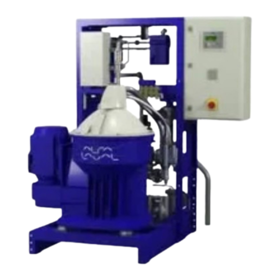
High Speed Separator
S 831 & S 836
Product No. 881202-03-04/1 & 881202-02-04/1
Book No.
592763-02 Rev. 1
Table of
Contents
Previous
Page
Next
Page
1
2
3
4
5
Advertisement
Table of Contents
Need help?
Do you have a question about the S 831 and is the answer not in the manual?
Ask a question
Questions and answers
Related Manuals for Alfa Laval S 831
Industrial Equipment Alfa Laval Pharma-line S 1 Instruction Manual
(18 pages)
Industrial Equipment Alfa Laval SaniMicro Instruction Manual
Rotary spray heads (56 pages)
Industrial Equipment Alfa Laval SaniMidget Instruction Manual
Rotary spray heads (56 pages)
Industrial Equipment Alfa Laval S 836 Manual
Fuel oil high speed separator - purifier (186 pages)
Industrial Equipment Alfa Laval MultiMidget Instruction Manual
Rotary spray heads (44 pages)
Industrial Equipment Alfa Laval M15 Instruction Manual
Gasketed plate-and-frame heat exchangers (46 pages)
Industrial Equipment Alfa Laval T2 Instruction Manual
Heating insulation for gasketed plate heat exchangers (27 pages)
Industrial Equipment Alfa Laval M15 Instruction Manual
Plate heat exchangers (21 pages)
Industrial Equipment Alfa Laval MMPX 303SGP-11 Manual
(181 pages)
Industrial Equipment Alfa Laval Contherm 6X3 Instruction Manual
Single wall scrape surface heat exchangers (124 pages)
Industrial Equipment Alfa Laval AQ Series Instruction Manual
Gasketed plate heat exchangers (46 pages)
Industrial Equipment Alfa Laval Mini City F2 Installation And Operating
(26 pages)
Industrial Equipment Alfa Laval T6 Instruction Manual
Cooling insulation for gasketed plate heat exchangers (26 pages)
Industrial Equipment Alfa Laval M6-MW Instruction Manual
Plate heat exchangers (54 pages)
Industrial Equipment Alfa Laval CPM-2 Instruction Manual
Constant-pressure modulating valve (36 pages)
Industrial Equipment Alfa Laval FrontLine WideGap 100 Instruction Manual
Plate heat exchangers (30 pages)
This manual is also suitable for:
S 836
Table of Contents
Print
Rename the bookmark
Delete bookmark?
Delete from my manuals?
Login
Sign In
OR
Sign in with Facebook
Sign in with Google
Upload manual
Upload from disk
Upload from URL


Need help?
Do you have a question about the S 831 and is the answer not in the manual?
Questions and answers