
Related Manuals for Pentair INTELLIFLO 2 VST


Summary of Contents for Pentair INTELLIFLO 2 VST
- Page 1 ® INTELLIFLO 2 VST VARIABLE SPEED PUMP INSTALLATION AND USER’S GUIDE IMPORTANT SAFETY INSTRUCTIONS READ AND FOLLOW ALL INSTRUCTIONS SAVE THESE INSTRUCTIONS...
-
Page 2: Table Of Contents
CUSTOMER SERVICE / TECHNICAL SUPPORT If you have questions about ordering Pentair Aquatic Systems replacement parts, and pool products, please contact: Customer Service and Technical Support, USA Sanford, North Carolina (8 A.M. to 4:30 P.M. ET) (8 A.M. to 4:30 P.M. — Eastern/Pacific Times) -
Page 3: Important Pump Warning And Safety Instructions
230 VAC charge even when there is no This guide provides installation and operation instructions for this pump. power to the unit. Consult Pentair with any questions regarding this equipment. • The pump is not submersible. Attention Installer: This guide contains important information about the •... - Page 4 (D) Disabled submerged outlets, or (E) Suction outlets shall be reconfigured into return inlets. Warnings and safety instructions for Pentair Aquatic Systems pumps and other related products are available at: For Installation of Electrical Controls at Equipment Pad (ON/OFF http://www.pentairpool.com/pool-owner/safety-warnings/ or call...
-
Page 5: Pump Overview
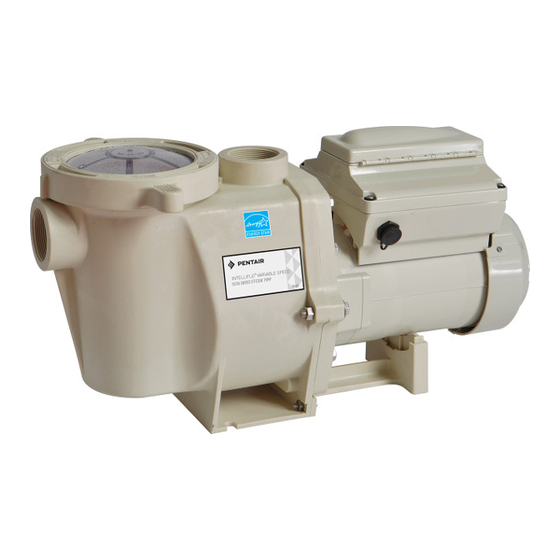
Totally Enclosed Fan Cooled (TEFC) Motor Drive Assembly and Control Panel • 56 Square Flange The IntelliFlo 2 VST pump drive is designed to produce • Low noise maximum motor operational efficiency. The drive controls the motor’s rotational speed by controlling the frequency Drive Features of the supplied current. -
Page 6: Installation
For installation instructions refer to the Keypad 4. For most installations Pentair recommends installing Relocation Kit Installation Instructions provided with a valve on both the pump suction and return lines the kit. -
Page 7: Electrical Installation
National Electric Code and any local in tandem with a Pentair salt chlorine generator. codes as required. 4. Use strain relief and be sure all electrical connections Bonding are clean and tight. -
Page 8: Operating The Pump
OPERATING THE PUMP NOTE: Speed 1 is the default filtration speed. ® NOTE: When setting up the IntelliFlo 2 VST Variable Speed Pump, the user must set the pump’s internal clock and establish an operation schedule by following the steps in this manual. Please refer to user’s guide sections: ‘Set Time’ (page 8) and ‘Set Speeds 1-8 in Schedule Mode’... -
Page 9: Using The Operator Control Panel
Using the Operator Control Panel Use the operator control panel to start and stop the IntelliFlo ® Key Lockout Icon VST Variable Speed Pump, program, set, and change speeds (RPM), and access pump features and settings. Controls and LEDs on Keypad 12:15p Button 1: Press to select Speed 1 (750 RPM). -
Page 10: Stopping And Starting The Pump
Stopping and Starting the Pump Manual Speed 1 (1-4) Set Speed - Defa Starting the Pump Schedule Set Speed 1. Be sure the pump is powered on and the green Set Start Time Set Stop Time power LED is on. Egg Timer Set Speed 2. -
Page 11: Control Panel: Pump Menu Guide
Operator Control Panel: Pump Menu Guide MENU Press MENU button to access menus SETTINGS Set Date and Time Date Months (1-12) Days (1-31) (pages 8-10) Years (2000-2050 Plus) Time Hours (24hr Mode: 0-23) (12hr Mode: 1-12 AM & PM) Minutes (0-60) Hour Format AM/PM - Default: AM/PM 24 Hour... -
Page 12: Pump Settings
Set Minimum Speed (RPM) can communicate to only four (1-4) pumps. The minimum pump speed can be set from 450 RPM Note: IntelliFlo 2 VST pumps cannot be connected in to 1700 RPM. The default setting is 450 RPM. series with other pumps. -
Page 13: Set Screen Contrast
MENU Pump Menu: Settings SETTINGS Pump Address (cont.) Set Temperature Unit 5. Use the Up or Down arrows to scroll to “Pump The default setting is Fahrenheit (°F). The pump can be Address” and press Select. set to either Celsius (°C) or Fahrenheit (°F). 6. -
Page 14: Setting Password
MENU MENU Pump Menu: Settings SPEED 1-8 Pump Menu: Speeds 1-8 SETTINGS Pump Operating Modes Setting Password 1. Check that the green power LED is on. ® The IntelliFlo 2 VST Variable Speed Pump can be programmed in three different modes: 2. -
Page 15: Set Speeds 1-4 In Manual Mode
MENU SPEED 1-8 Pump Menu: Speeds 1-8 Set Speeds in Manual Mode Set Speeds 1-8 in Schedule Mode (Speeds 1-4 Only) In Schedule mode, Speeds 1-8 can be programmed 1. Press Menu. to run a certain speed at a certain time of day. To run a scheduled speed, press Start/Stop. -
Page 16: External Control
MENU MENU Pump Menu: External Pump Menu: Speeds 1-8 EXT CONTROL SPEED 1-8 Control Set Speeds 1-8 in Schedule Mode (cont.) External Control This function is for programming speeds that will run Programming Schedule for Constant Run ® when the IntelliComm Communication Center sends A speed cannot be programmed with the same start it a command. -
Page 17: Features
MENU 10. Press Select to change the time. The cursor will highlight the minutes column. Pump Menu: Features FEATURES 11. Use Up or Down arrows to change the time from 1 minute to 10 hours. Time Out 12. Press Save to save the time. The Time Out feature keeps the pump from running it’s 13. -
Page 18: Priming Features
MENU PRIMING Pump Menu: Priming Priming Features Default: ENABLED DISABLED/ENABLED Allows IntelliFlo ® 2 VST Variable Speed Pump to automatically detect if pump if is primed for startup. The pump will speed up to 1800 RPM and pause for three (3) seconds - if there is enough water in the basket, the pump will go out of priming mode and run the commanded speed. -
Page 19: Setting Priming Features
MENU PRIMING Pump Menu: Priming Setting Priming Features 16. Press Save to save the setting. 17. Press Back to exit. Note: Priming features are only accessible if priming is “Enabled”. Disabling Priming with an Automation 1. Press Menu. System 2. Use Down arrow to scroll to “Priming” and press ®... -
Page 20: Thermal Mode
MENU Pump Menu: Thermal Mode THERMAL MODE The sensor for Thermal Mode is in the drive, on top of To Set Thermal Mode Speed and Pump Temperature: the motor. This feature allows you to set a speed (450 Note: Thermal Mode features are only accessible if ®... -
Page 21: Connecting To An Automation System
CONNECTING TO AN AUTOMATION SYSTEM ® Wiring Terminal Descriptions for IntelliComm External Control with IntelliComm Communication Center Communication Center Use the RS-485 communications cable to remotely Terminal Terminal Max. Phase ® control the IntelliFlo 2 VST Variable Speed Pump Voltage Frequency Number Name... - Page 22 To connect the IntelliFlo ® 2 VST Variable Speed ® Pump communication cable to EasyTouch ® IntelliTouch Control System load center: 1. Switch the main power off to the load center. IntelliTouch COM port (J7/8): Connect the GREEN (#2) and YELLOW (#3) wires to the COM port (J20) 2.
-
Page 23: Connecting To Suntouch Control System
® Connecting the Pump to a SunTouch Control System The IntelliFlo ® 2 VST Variable Speed Pump can be Switch OFF main system power to the SunTouch controlled by a SunTouch system via the RS-485 system power center before making any communication cable. -
Page 24: Maintenance
MAINTENANCE ® DO NOT open the strainer pot if IntelliFlo 2 VST Variable Speed Pump fails to prime or if pump has been operating without water in the strainer pot. Pumps operated in these circumstances may experience a build up of vapor pressure and may contain scalding hot water. -
Page 25: Servicing
The pump impeller may have sharp edges that could The Shaft Seal consists primarily of two parts, a rotating potentially cut or scratch the user's hands. Pentair ceramic seal housed in the impeller and a stationary recommends that safety gloves be worn when holding the impeller during disassembly and reassembly. -
Page 26: Pump Reassembly
Pump Reassembly 10. Reinstall the pump lid and plastic locking ring. See “Cleaning the Pump Strainer Basket” on page 20 1. When installing the replacement shaft seal, use for details silicone sealant on the metal portion before pressing 11. Reconnect the RS-485 communication cable to into the seal plate as shown. -
Page 27: Alerts And Warnings
Indicates that the self-monitoring motor control software pump provides an automatic internal cutoff switch to protect the motor has encountered an error. Clear the alarm and restart from heat damage during operation. the pump. If this alarm persists, contact Pentair Technical Service at 1-800-831-7133. INTELLIFLO ®... -
Page 28: Troubleshooting
TROUBLESHOOTING Always disconnect power to the IntelliFlo ® 2 VST Variable Speed Pump at the circuit breaker and disconnect the communication cable before servicing the pump. Failure to do so could result in death or serious injury to serviceman, pool users or others due to electric shock. - Page 29 Troubleshooting, (continued) Problem Possible Cause Corrective Action Electrical problem. Could appear as a “Low Voltage” alarm. Check voltage at motor terminals and at panel while pump is running. If low, see wiring instructions or (For alert display consult power company. messages, refer to Alerts and Warning on page 23).
-
Page 30: Replacement Parts
WASHER, FLAT 3/8" ID x 7/8" OD (QTY 6) (Contains Items #24-26) 070430 BOLT, HEX HEAD 3/8-16 x 1.25" (QTY 4) 354044 POWER END - INTELLIFLO 2 VST 070431 BOLT, HEX HEAD 3/8-16 x 2" (QTY 2) 357603 UNION KIT (Contains 2 Complete Unions for 1 350305S MOTOR, 3.2 kW 10 POLE... -
Page 31: Technical Data
Pump Dimensions Electrical Specifications Circuit Protection: Two-pole 20 AMP device at the Electrical Panel. Input: 208-230 VAC, 50/60 Hz, 3200 Watts Maximum, 1 phase Pump Performance Curves MAX SPEED @3450 RPM SPEED 4 - 3110 RPM SPEED 3 - 2350 RPM SPEED 2 - 1500 RPM SPEED 1 - 750 RPM FLOW RATE IN US GALLONS PER MINUTE... -
Page 32: Operator Control Panel Quick Reference Guide
Operator Control Panel: Pump Menu Quick Reference Guide MENU Press MENU button to access menus SETTINGS Set Date and Time Date Months (1-12) Days (1-31) (pages 8-10) Years (2000-2050 Plus) Time Hours (24hr Mode: 0-23) (12hr Mode: 1-12 AM & PM) Minutes (0-60) Hour Format AM/PM - Default: AM/PM... - Page 33 NOTES...
- Page 34 NOTES...
- Page 35 NOTES...
- Page 36 United States and/or other countries. Unless expressly noted, names and brands of third parties that may be used in this document are not used to indicate an affiliation or endorsement between the owners of these names and brands and Pentair Water Pool and Spa, Inc. Those names and brands may be the trademarks or registered trademarks of those third parties.
Need help?
Do you have a question about the INTELLIFLO 2 VST and is the answer not in the manual?
Questions and answers