Table of Contents
Advertisement
Quick Links
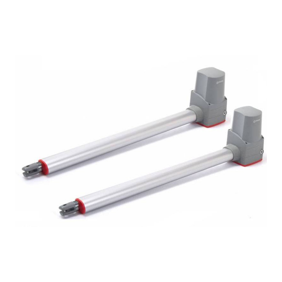
TEMIS
Quick Installation Guide
This quick guide is a summary of the complete installation manual. The manual contains safety warnings and
other explanations which must be taken into account. The installation manual can be downloaded by going
WARNING
to the "Downloads" section of Erreka website:
http://www.erreka-automation.com
G
D
C
Electrical Wiring
A.B: 24v DC Motor(2x1mm²)
C: Photocell 2x0.5mm² (max 20m)
D: Control Box (3x1.5mm²)
E: Push Botton 2x0.5mm²(max 25m)
TEMIS It is not applicable to an insecure or lacking rigidity door nor solves the defects due to incorrect installation or mainte-
Check the following points before starting the installation:
1). Hinges are properly positioned and greased.
2). No obstacles in the moving area and no frictions between two gate leafs or with the ground while moving.
3). "C" value is 139mm.
4). "D" can be measured from the gate easily.
5). "A" = "C" + "D"
6). The value of "B" can be calculated from the value of "A" and the leaves opening angle.
Ex. If "A"=160mm with the leaves opening angle of 100 degrees, then the value of "B" is approximate 190mm.
B
D
A
C
A
TA
F: Key Selector(2x0.5 mm²)
G: Flash Light (2x0.5mm²)
H.I: Electric Lock (2x1mm²)
Assembly levels, inward opening
D Aprox
Please make sure B and A are similar or the same in value that the leaves can be
operated smoothly, also to reduce the burden of the motor.
Elements of the complete installation
H
TC
I
A
140
150
160
170
180
190
200
210
E
0
B
TA
TA: Open Stopper
TC: Closed Stopper
B
140
150 160 170 180 190
200 210
>120°
110°~120°
100°~110°
90°~100°
Open Interior
MSB-026/04
F
1
Advertisement
Table of Contents

Related Manuals for Erreka TEMIS


Summary of Contents for Erreka TEMIS
- Page 1 E: Push Botton 2x0.5mm²(max 25m) Assembly levels, inward opening TEMIS It is not applicable to an insecure or lacking rigidity door nor solves the defects due to incorrect installation or mainte- Check the following points before starting the installation: 1). Hinges are properly positioned and greased.
- Page 2 Assembly levels, outward opening Open exterior Please make sure B and A are similar or the same in value that the leaves can be operated smoothly, also to reduce the burden of the motor. Unlocking Unlocking for manual operation: Motorised operation locking: 1.
- Page 3 Release the gate opener with the door in closed position. Place the front bracket without fixing it.. Check the door manually which can be moved easily in entire route. D Aprox Horizontal 180 Block the motor and make the electrical wiring to connect the cables M1 and M2 correctly. If you only install one gate, connect the wires to the terminal M1.
- Page 4 Electrical connections Transformer Batteries connection Batteries recharger incorporated in control board, no need to connect extra recharger. Maximum batteries capacity connection is up to 15Ah. The battery housing on the box is prepared for 2 batteries of 1.3 Ah. LED Display DOWN RF-LEARN LED1 System Learning...
- Page 5 Display indications LED Display Programmable Functions “N-L”: The system learning is not done. “CLN” the memory of the system is all cleaned/deleted. Press “UP+DOWN” for 5 seconds. “RUN”: The system is in normal “ME”: Motor operation error. performing. “LEA”: Enter learning mode and then “STP”: the motor stop in the middle of wait for learning instructions.
- Page 6 Radio code programming Press and hold the RF-Learn for 1 Press A button for 5 seconds for double leaf Press B button for 5 seconds for single-gate second, the blue LED on the RF board gate Radio code programming installation. installation.
- Page 7 Complete programming chart (1) LED Display Definition Parameter Mode Description Encoder/ Limit switch F1-1 Motor only 1. The factory setting is "F1-1". F1-2 Motor with limit switch F1-3 Motor with encoder Number of operators F2-1 Two Operators 1. The factory setting is "F2-1". F2-2 One Operator F3-1...
- Page 8 Complete programming chart (2) LED Display Definition Parameter Mode Description 1. The factory setting is "FC-0". Photocell1 FC-0 FC-1 Photocell2 FD-0 1. The factory setting is "FD-0". FD-1 Buzzer Function FE-0 1. The factory setting is "FE-0". FE-1 Reverse Impulse for FF-0 1.
Need help?
Do you have a question about the TEMIS and is the answer not in the manual?
Questions and answers