
Related Manuals for OmniPrint OM9300

Summary of Contents for OmniPrint OM9300
- Page 1 OM9300 User’s Manual Revision: 1.0 January 22, 2018 OMNIPrint Inc. 1923 East Deere Ave. Santa Ana, California, 92705, U.S.A. T: 949-833-0080 :: F: 949-833-0040 www.omniprintinc.com...
-
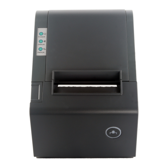
Page 2: Printer Appearance
1. Printer Appearance Rear View Front View Right Side View Left Side View... - Page 3 1.1 Switch and LED Functions 1. Feed Button Press to feed paper manually; release to stop feeding. 2. Paper Status When both Error and Paper LEDs are on, printer is out of paper. When both Error and Paper LEDs are off, printer has paper. When only the Paper LED is on, paper is low.
-
Page 4: Printer Setup
2. Printer Set Up Unpacking The items illustrated below are included in the printer package. If any items are damaged or missing, please contact your supplier for assistance: RS-232 POWER ADAPTER POWER CORD INTERFACE CABLE MANUAL PAPER ROLL... -
Page 5: Connecting The Power Adapter
Connecting the Cables Before connecting the cables, please make sure that both the printer and host are turned off. 2.2.1 Connecting the Power Adapter An approved Class 2 external switching power supply is required for the operation of this product. A detachable power cord with an appropriate plug type is also provided. -
Page 6: Paper Loading
3. Paper Loading Use a paper roll that meets the specifications below. Do not use paper rolls that are glued to the core. Make sure data is not being transmitted to the printer while loading paper. 1. To open the paper cover push the latch located on the left, as indicated in illustration “a”. 2. -
Page 7: Setting The Dip Switch
4. Dip Switch Setting the Dip Switch An 8 position DIP switch is located on the bottom of the printer unit. Gently turn the printer over and use a small Philips screw driver to remove the cover. By changing the switch positions you can modify the default setting for various functions such as cutter mode, character set, beeper, printer speed etc. - Page 8 5. Self Test You can perform a self test to determine the default settings and obtain the printer revision number. First, make sure the printer is turned off and then while pressing the Paper Feed button turn the printer on. The printer starts printing its factory setting. 5.1 Code Page Setting Refer to the Self Test page code details, for example: For English:...
- Page 9 Control command summary Command Function Horizontal tab Print and line feed Print and carriage return Print end position label to start printing Cancel print data in page mode DLE EOT Real-time status transmission DLE ENQ Real-time request to printer DLE DC4 Generate pulse at real-time ESC FF Print data in page mode...
- Page 10 62 GS v 0 Print raster bit image 63 GS w Set bar code width < Add > ESC I Full cut ESC m Partial cut Please see OMNIPrint Printer Control Command Set document for detailed explanation of the command codes.
- Page 11 Consult your authorized reseller or service representative for help. Properly shielded and grounded cables and connectors must be used in order to meet FCC emission limits. Proper cables and connectors are available from OMNIPRINT INC. authorized dealers. INDUSTRY CANADA CLASS A EMISSION COMPLIANCE STATEMENT This Class A digital apparatus meets all the requirements of the Canadian Interference- Causing Equipment Regulations.
Need help?
Do you have a question about the OM9300 and is the answer not in the manual?
Questions and answers