Tektronix WVR7200 Service Manual
Waveform rasterizer
Hide thumbs
Also See for WVR7200:
- Technical reference (135 pages) ,
- Installation and safety manual (83 pages) ,
- Declassification and security instructions (11 pages)
Table of Contents
Advertisement
Quick Links
Advertisement
Table of Contents
Troubleshooting

Related Manuals for Tektronix WVR7200


Summary of Contents for Tektronix WVR7200
- Page 1 WVR7200 Waveform Rasterizer Service Manual *P077067600* 077-0676-00...
- Page 3 WVR7200 Waveform Rasterizer Service Manual www.tektronix.com 077-0676-00...
- Page 4 Copyright © Tektronix. All rights reserved. Licensed software products are owned by Tektronix or its subsidiaries or suppliers, and are protected by national copyright laws and international treaty provisions. Tektronix products are covered by U.S. and foreign patents, issued and pending. Information in this publication supersedes that in all previously published material.
- Page 5 Tektronix, with shipping charges prepaid. Tektronix shall pay for the return of the product to Customer if the shipment is to a location within the country in which the Tektronix service center is located. Customer shall be responsible for paying all shipping charges, duties, taxes, and any other charges for products returned to any other locations.
-
Page 7: Table Of Contents
General Maintenance....................Preventing ESD ....................Inspection and Cleaning..................Troubleshooting....................Detailed Troubleshooting Procedures ..............Repackaging Instructions ..................Packaging ...................... Shipping to the Service Center ................Replaceable Parts ....................Parts Ordering Information .................. Using the Replaceable Parts Lists................WVR7200 Waveform Rasterizer Service Manual... - Page 8 Figure 6: Replaceable parts (standard) ................Figure 7: Replaceable parts (standard) ................Figure 8: Replaceable parts (options) ................Figure 9: Replaceable parts (WVR8RFP Remote Front Panel) ..........Figure 10: Analog audio breakout cable assembly ............WVR7200 Waveform Rasterizer Service Manual...
- Page 9 Table 1: External inspection check list................Table 2: Internal inspection check list................Table 3: Required test equipment................Table 4: Symptoms and causes .................. Table 5: Main board secondary supplies ................ Table 6: Audio board secondary supplies............... WVR7200 Waveform Rasterizer Service Manual...
-
Page 10: General Safety Summary
Recharge batteries properly. Recharge batteries for the recommended charge cycle only. Use proper fuse. Use only the fuse type and rating specified for this product. Wear eye protection. Wear eye protection if exposure to high-intensity rays or laser radiation exists. WVR7200 Waveform Rasterizer Service Manual... - Page 11 DANGER indicates an injury hazard immediately accessible as you read the marking. WARNING indicates an injury hazard not immediately accessible as you read the marking. CAUTION indicates a hazard to property including the product. The following symbol(s) may appear on the product: WVR7200 Waveform Rasterizer Service Manual...
-
Page 12: Service Safety Summary
Use care when servicing with power on. Dangerous voltages or currents may exist in this product. Disconnect power, remove battery (if applicable), and disconnect test leads before removing protective panels, soldering, or replacing components. To avoid electric shock, do not touch exposed connections. WVR7200 Waveform Rasterizer Service Manual... -
Page 13: Preface
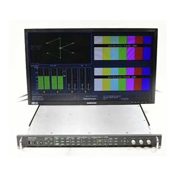
Preface This manual supports servicing to the module level of the WVR7200 Waveform Rasterizer, which rasterizes video signals for XGA display. The rasterizer can be used as a monitor for broadcasting, production, and post-production environments. This manual explains how to troubleshoot and service the rasterizer to the module level. - Page 14 Procedure for checking performance and Product Documentation CD Specifications and Performance list of specifications www.tektronix.com/manuals Verification WVR and WFM Series Master Information Programmers command reference for Product Documentation CD Base (MIB) controlling the waveform rasterizer www.tektronix.com/manuals viii WVR7200 Waveform Rasterizer Service Manual...
-
Page 15: Introduction
The performance verification procedures for this product are found in the WVR7200 Waveform Rasterizer Specifications and Performance Verification Technical Reference located on the Product Documentation CD that ships with the product and is published on the Tektronix Web site. (See page vii, Related Manuals.) Options and Accessories... -
Page 16: Hardware Installation
Product Upgrade Hardware and software upgrades are available for all products, either as a field upgrade kit or as a free software download from the Tektronix Web site. The WVR7200 Waveform Rasterizer User Manual includes instructions for updating product firmware. -
Page 17: Theory Of Operation
Theory of Operation The WVR7200 is a modular waveform rasterizer. They can be configured, with options, to accept Analog Composite inputs. Audio options can add inputs for digital only or analog audio capability. All models use an external DVI-I monitor for the display. All models also have outputs to drive serial digital and analog picture monitors. -
Page 18: Figure 1: Main Block Diagram
Theory of Operation Power Distribution is not shown in the block diagram but is covered at the end of this section. Figure 1: Main block diagram WVR7200 Waveform Rasterizer Service Manual... -
Page 19: Main Board
It draws the audio bars, communicates with the front panel, and controls most other internal devices though either the SPI or the I C bus. Audio data is input to the control processor via the 8 bit HPI bus. WVR7200 Waveform Rasterizer Service Manual... -
Page 20: Front Panel
On the second path, raw data samples are sent to the waveform processing engine which interpolates and plots it to generate the lissajous, or “phase,” display. WVR7200 Waveform Rasterizer Service Manual... -
Page 21: Option Phy3
Option PHY3 provides the following features: Eye pattern display Equalized Eye pattern display Jitter readout Jitter Meter Cable Loss readout Test Signal Output Approx Cable readout Source Level readout Jitter waveform display Eye Amplitude readout Eye Risetime readout WVR7200 Waveform Rasterizer Service Manual... - Page 22 The selected SDI input signal also drives the Cable Meter circuit, which measures signal energy at two frequencies. These measurements are read by the CPU on the Main board, which calculates Cable Loss, Approximate Cable Length, and Source Level for display in the SDI Status screen. WVR7200 Waveform Rasterizer Service Manual...
-
Page 23: Figure 2: Option Phy3 Block Diagram
Theory of Operation Figure 2: Option PHY3 block diagram WVR7200 Waveform Rasterizer Service Manual... -
Page 24: Fan Control
Fuses on the Primary supply 5 V output protect the main board. The secondary supplies and their tolerances are specified in the troubleshooting section. The location of the supply test points is shown in the Maintenance section. WVR7200 Waveform Rasterizer Service Manual... -
Page 25: Adjustments
Verification procedure. For more details refer to Specifications and Performance Verification. Procedures NOTE. If you do not see the calibration case you are looking for, make sure to go to the next page using the up or down arrow key. WVR7200 Waveform Rasterizer Service Manual... - Page 26 2. Press the CONFIG button, and then select Utilities > Calibration. Press SEL to enter the calibration menu. 3. Use the up and down arrow buttons to navigate to the appropriate Eye Gain Adjust selection, and press SEL to start the calibration. WVR7200 Waveform Rasterizer Service Manual...
- Page 27 2. Connect an XGA to 5x BNC adapter cable to the PixMon output. 3. Connect the Y/Green video signal to the oscilloscope input. (Use an oscilloscope with a 75 Ω input, or a 75 Ω feed through termination.) WVR7200 Waveform Rasterizer Service Manual...
- Page 28 8. Adjust the oscilloscope trigger level for a stable display. 9. Use the General knob to adjust the signal zero level to 0 V on the oscilloscope. 10. Follow the instructions at the bottom of the calibration screen to Save and Exit Calibration mode. WVR7200 Waveform Rasterizer Service Manual...
- Page 29 6. Follow the on-screen instructions to adjust the response. 7. Follow the instructions at the bottom of the screen to Save and Exit calibration mode. 8. Repeat the Composite Analog Frequency Response test in the Performance Verification procedure. WVR7200 Waveform Rasterizer Service Manual...
- Page 30 7. Check for an indication of 18 dBu in the newly adjusted audio bar. 8. If multiple inputs require adjustment, repeat this procedure for each input. 9. After all adjustments are made, you should perform a complete performance verification procedure. WVR7200 Waveform Rasterizer Service Manual...
-
Page 31: General Maintenance
Do service of static-sensitive modules only at a static-free work station. 4. Nothing capable of generating or holding a static charge should be allowed on the work station surface. 5. Handle circuit boards by the edges when possible. WVR7200 Waveform Rasterizer Service Manual... -
Page 32: Inspection And Cleaning
Use only deionized water when cleaning the front-panel buttons. Use a 75% isopropyl alcohol solution as a cleaner and rinse with deionized water. Before using any other type of cleaner, consult your Tektronix Service Center or representative. WVR7200 Waveform Rasterizer Service Manual... -
Page 33: Table 1: External Inspection Check List
Burned circuit boards. Burned, broken, or cracked circuit-run plating. Resistors Burned, cracked, broken, Remove and replace blistered condition. damaged circuit board. Solder connections Cold solder or rosin joints. Resolder joint and clean with isopropyl alcohol. WVR7200 Waveform Rasterizer Service Manual... -
Page 34: Troubleshooting
General Safety Summary and Service Safety Summary found at the beginning of this manual. To prevent possible injury to service personnel or damage to electrical component, refer on how to prevent ESD. (See page 17.). WVR7200 Waveform Rasterizer Service Manual... - Page 35 Unknown Problem section in the Symptoms and Causes table. The WVR7200 Waveform Rasterizer is highly configurable and behavior is sometimes complex. Before troubleshooting in-depth, verify that: The installed options are as expected.
-
Page 36: Table 3: Required Test Equipment
Computer monitor capable of 1024 x 768 x 60 Hz scan rate SDI serial digital video test generator with 1080p 59.94 3 Gb/s HD signals required: Tektronix TG700 with an HD3G7 module embedded audio and composite signal (Embedded audio needed for audio 100% color bars... -
Page 37: Table 4: Symptoms And Causes
Eye Hardware Revision Perform secondary power supply checks Eye Board Cable Version Run Advanced Diagnostics and look for other information Replace the EYE/PHY board Eye Register Readback Eye Board Power Supply Eye Board Cal EEPROM WVR7200 Waveform Rasterizer Service Manual... - Page 38 DSY SDRAM Buffer 1 Memory DSY SDRAM Buffer 2 Memory Diagnostic Log Message: Search for an intermittent problem in the audio board, cables, or main board. Fail AUDIO_DSP_HEARTBEAT No text or traces on display Replace Main board WVR7200 Waveform Rasterizer Service Manual...
- Page 39 The Audio board can place too much of a load on the supplies if they are marginal. If the performance changes with the audio board removed, then you should perform the primary and secondary power supply checks and look for an excess load on one of the supplies. WVR7200 Waveform Rasterizer Service Manual...
-
Page 40: Detailed Troubleshooting Procedures
If a fan is not spinning, measure the voltage on pin 1 of the connector on that fan. If the voltage is near 13 V, then replace the fan. If the voltage is not above 10 V, then replace the main board. WVR7200 Waveform Rasterizer Service Manual... - Page 41 If that does not correct the problem, there may be a main board failure in the power switch circuit. WVR7200 Waveform Rasterizer Service Manual...
-
Page 42: Table 5: Main Board Secondary Supplies
2.4 to 2.6 + 2.5 V 1.4 to 1.6 + 1.5 V 0.95 to 1.05 + 1.0 V 4.75 to 5.25 + 5 VA -4.75 to -5.25 – 5 VA 1.2 to 1.4 + 1.2 V WVR7200 Waveform Rasterizer Service Manual... -
Page 43: Table 6: Audio Board Secondary Supplies
1. Connect an external XGA monitor to the DVI Primary output on the rear of the instrument. 2. Cycle the power and watch the external monitor. If the monitor does not display the boot up messages and normal operational screen, replace the main board. WVR7200 Waveform Rasterizer Service Manual... - Page 44 If the signal does transition, check pin 33 of J200 on the audio board. If the signal does not toggle on pin 33, replace the cable. WVR7200 Waveform Rasterizer Service Manual...
- Page 45 Check to see if surround display is functioning correctly by doing the following. i. Press and hold the Audio button. ii. In the audio menu, select Aux Display > Surround Display. iii. Press the Audio Input Menu button, then select Audio Input > AES WVR7200 Waveform Rasterizer Service Manual...
- Page 46 The audio Lissajous phase display uses a serial data path between the audio and main boards. A failure in this data path can be due to a problem on either board. Errors Perform the following tests to isolate the problem to one board or the other. WVR7200 Waveform Rasterizer Service Manual...
- Page 47 Pin 63 is the data line and the signal will have a somewhat random look depending on the audio source. Verify that the signal is toggling and is ≈3 V e. If either signal is bad, suspect the cable; otherwise replace the main board. WVR7200 Waveform Rasterizer Service Manual...
- Page 48 Operation is unlikely to fail if the basic Eye pattern display works correctly. It is normal for these measurements to stop or become intermittent if there is excessive waveform noise, aberrations, jitter, or cable loss. WVR7200 Waveform Rasterizer Service Manual...
-
Page 49: Figure 3: Main Board Indicator Led, Connector, And Test Point Locations
General Maintenance Figure 3: Main board indicator LED, connector, and test point locations WVR7200 Waveform Rasterizer Service Manual... -
Page 50: Figure 4: Options Ad And Dpe Audio Board, Component Side
General Maintenance Figure 4: Options AD and DPE Audio board, component side WVR7200 Waveform Rasterizer Service Manual... -
Page 51: Figure 5: Options Ad And Dpe Audio Board Back Side Indicator Led And Test Point Locations
General Maintenance Figure 5: Options AD and DPE Audio board back side indicator LED and test point locations WVR7200 Waveform Rasterizer Service Manual... -
Page 52: Repackaging Instructions
Type and serial number of the instrument. Reason for returning. A complete description of the service required. Mark the address of the Tektronix Service Center and the return address on the shipping carton in two prominent locations. WVR7200 Waveform Rasterizer Service Manual... -
Page 53: Replaceable Parts
For more information about the module exchange program, call 1-800-833-9200. Outside North America, contact a Tektronix sales office or distributor; see the Tektronix Web site for a list of offices: www.tektronix.com. Module Repair and Return. You may ship your module to us for repair, after which we will return it to you. -
Page 54: Using The Replaceable Parts Lists
Orderable modules show the figure number without an index number. Tektronix part number Use this part number when ordering replacement parts from Tektronix. 3 and 4 Serial number Column three indicates the serial number at which the part was first effective. - Page 55 6 MM DIA SHAFT, 17.5 MM LENGTH SHAFT, 12 MM BODY SIZE, TOP MOUNT; RE0123 366-0859-01 ASSEMBLY, KNOB; .470 DIAMETER, SOFT TOUCH 335-22876-00 LABEL, FRONT PANEL, LEXAN, ID WVR7200, SAFETY CONTROLLED 101-0179-00 TRIM, FRONT PANEL, WVR, SAFETY CONTROLLED 260-2890-00 SWITCH, KEYPAD, ELASTOMERIC 863-0259-01 CIRCUIT BOARD SUBASSY;WVR FP...
- Page 56 OUTPUT, WITH CONN & HOUSING, SAFETY CONTROLLED 211-1161-00 SCREW,MACHINE; 4-40 X 1.500,PAN HEAD,T-10 TORX,ZINC PL 407-5375-00 BRACKET; FAN MOUNTING, 0.050 AL, SAFETY CONTROLLED 210-0457-00 NUT, PL, ASSEM WA; 6-32 X 0.312, W/LOCKWASHER, STEEL, ZINC FINISH WVR7200 Waveform Rasterizer Service Manual...
-
Page 57: Figure 6: Replaceable Parts (Standard)
Replaceable Parts Figure 6: Replaceable parts (standard) WVR7200 Waveform Rasterizer Service Manual... - Page 58 CABLE ASSEMBLY; POWER SUPPLY, 10 PIN, SAFETY CONTROLLED 174-5683-00 CABLE ASSEMBLY, CAT5E, MALE TO MALE, ETHERNET 174-5653-00 CABLE ASSEMBLY; POWER SUPPLY, HIGH CURRENT; SAFETY CONTROLLED 174-5682-00 CABLE ASSEMBLY, FRONT PANEL, 10 PIN Quantity varies with instrument options. WVR7200 Waveform Rasterizer Service Manual...
-
Page 59: Figure 7: Replaceable Parts (Standard)
Replaceable Parts Figure 7: Replaceable parts (standard) WVR7200 Waveform Rasterizer Service Manual... - Page 60 WASHER, LOCK; 0.521 ID, INT, 0.025 THK, STEEL, ZINC FINISH 220-0497-00 NUT, PLAIN, HEX; .5-28 X .562 HEX, BRS, NI (NICKEL) PLATED 211-0722-00 SCREW, MACHINE; 6-32 X 0.250, PNH, STEEL, ZINC FINISH, T-15 TORX DR WVR7200 Waveform Rasterizer Service Manual...
-
Page 61: Figure 8: Replaceable Parts (Options)
Replaceable Parts Figure 8: Replaceable parts (options) WVR7200 Waveform Rasterizer Service Manual... - Page 62 Name & description Standard Accessories 071-3024-xx SAFETY AND INSTALLATION INSTRUCTIONS (EN, JA, ZH), WVR7200 020-3103-xx DOCUMENTATION CD KIT, WVR7200, contains CD 063-4428-xx 071-2589-xx MANUAL, TECH; ND-NC; TEKTRONIX SUPPLEMENTAL INFORMATION SHEET FOR THE PEOPLES REPUBLIC OF CHINA; CHINA ROHS 071-2589-xx MANUAL, TECH;A PRINTED SHEET WITH MULTILANGUAGE POINTERS TO...
- Page 63 REMOTE FRONT PANEL LABEL, WVR, SAFETY CONTROLLED Standard Accessories 071-2804-xx WVR8RFP REMOTE FRONT PANEL INSTRUCTIONS 071-2181-xx MANUAL, TECH; ND-NC; TEKTRONIX SUPPLEMENTAL INFORMATION SHEET FOR THE PEOPLES REPUBLIC OF CHINA; CHINA ROHS 012-1721-00 CABLE ASSY;25 FT.,W/CONNECTOR,D-SUB,9 PIN MALE Optional Accessories 012-1720-00 CABLE ASSY;100 FT., W/CONNECTOR, D-SUB, 9 PIN MALE...
- Page 64 CABLE ASSY, PWR; 3, 1.0MM SQ, 250V/10A, 2.5 METER, STR, IEC320, 3C CERTIFICATION, RCPT, CHINA, SAFETY CONTROLLED 161-0400-00 Option A11 India CABLE ASSY, PWR; 3, 1.0MM SQ, 250V/6A, 2.5 METER, STR, IEC320/C13, RCPT, PLUG, INDIA WVR7200 Waveform Rasterizer Service Manual...
-
Page 65: Figure 9: Replaceable Parts (Wvr8Rfp Remote Front Panel)
Replaceable Parts Figure 9: Replaceable parts (WVR8RFP Remote Front Panel) WVR7200 Waveform Rasterizer Service Manual... -
Page 66: Figure 10: Analog Audio Breakout Cable Assembly
Analog Audio Breakout Cable Optional Accessory 012-1688-00 CABLE ASSEMBLY; ANALOG/AUDIO BREAKOUT 200-4804-00 COVER; SHIELD,ELEC CONN,37 POS DSUB,ZINC 131-0422-00 CONN,DSUB; SLDR CUP/PNL,;MALE,STR,37 POS,0.112 CTR,0.186 H X 0.126 TAIL,0.125 DIA THRU MTG Figure 10: Analog audio breakout cable assembly WVR7200 Waveform Rasterizer Service Manual...
Need help?
Do you have a question about the WVR7200 and is the answer not in the manual?
Questions and answers