Tektronix WVR6020 Technical Reference
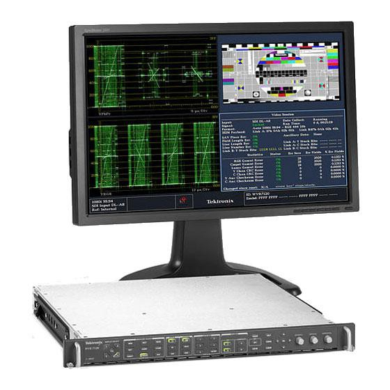
Waveform rasterizers
Hide thumbs
Also See for WVR6020:
- Quick start manual (145 pages) ,
- Service manual (87 pages) ,
- Technical reference (138 pages)

Subscribe to Our Youtube Channel
Related Manuals for Tektronix WVR6020


Summary of Contents for Tektronix WVR6020
- Page 1 WVR6020, WVR7020, WVR7120, WVR6100 Opt. MB, WVR7000 Opt. MB, and WVR7100 Opt. MB Waveform Rasterizers Technical Reference *P077008201* 077-0082-01...
- Page 3 WVR6020, WVR7020, WVR7120, WVR6100 Opt. MB, WVR7000 Opt. MB, and WVR7100 Opt. MB Waveform Rasterizers Technical Reference www.tektronix.com 077-0082-01...
- Page 4 Copyright © Tektronix. All rights reserved. Licensed software products are owned by Tektronix or its subsidiaries or suppliers, and are protected by national copyright laws and international treaty provisions. Tektronix products are covered by U.S. and foreign patents, issued and pending. Information in this publication supersedes that in all previously published material.
- Page 5 Warranty Tektronix warrants that this product will be free from defects in materials and workmanship for a period of one (1) year from the date of shipment. If any such product proves defective during this warranty period, Tektronix, at its option, either will repair the defective product without charge for parts and labor, or will provide a replacement in exchange for the defective product.
-
Page 7: Table Of Contents
Table of Contents Table of Contents General Safety Summary ......................Preface .. - Page 8 Table of Contents Waveform Rasterizers Technical Reference...
-
Page 9: General Safety Summary
General Safety Summary General Safety Summary Review the following safety precautions to avoid injury and prevent damage to this product or any products connected to it. To avoid potential hazards, use this product only as specified. Only qualified personnel should perform service procedures. To Avoid Fire or Personal Injury Use Proper Power Cord. - Page 10 General Safety Summary Terms in this Manual These terms may appear in this manual: WARNING. Warning statements identify conditions or practices that could result in injury or loss of life. CAUTION. Caution statements identify conditions or practices that could result in damage to this product or other property. Symbols and Terms on the Product These terms may appear on the product: DANGER indicates an injury hazard immediately accessible as you read the marking.
-
Page 11: Preface
Preface Preface This manual contains supplemental user information for the following instruments: WVR6020 WVR7020 WVR7120 WVR6100 with Option MB WVR7000 with Option MB WVR7100 with Option MB Where to Find More Information Item Purpose Location Quick Start User Manual Installation and high-level... - Page 12 Preface Waveform Rasterizers Technical Reference...
-
Page 13: Incoming Inspection
Incoming Inspection Incoming Inspection The incoming inspection procedures are optional procedures that check the functionality of the instrument and require no equipment other than a display. For a more robust inspection, see the performance verification procedures in the Specifications and Performance Verification manual that is included on the User Documentation CD that was shipped with your instrument. - Page 14 Incoming Inspection Front Panel Test 1. Press FACTORY to restore the factory preset. Wait for the progress indicator to show the process is complete. 2. Press FULL to make the active tile be full screen. 3. Press HELP to display the help screen. 4.
- Page 15 Incoming Inspection XGA and Extended Diagnostics Test Where the following procedure says to press an arrow key, you can use the general knob on the front panel, NOTE. if you prefer. 1. Press the CONFIG button to display the configuration menu. 2.
- Page 16 Incoming Inspection 7. Verify that the frequencies shown are within 10 kHz, and that rates shown are within 0.1 μs, of the nominal values listed to the right. 8. Verify that the bus bit activity tests QDR Clock = 25.174 MHz (labeled Channel A:, Processor Video:, VGA clock = 64.480 MHz and Composite Video:, and appearing at...
-
Page 17: Installation Variations
Installation Variations Installation Variations See the Quick Start User Manual that was shipped with your instrument for basic installation instructions. Read the following information for other installation situations and for remote communication instructions, an optional procedure that is suitable for incoming inspection of this product. Connecting Directly to a PC The following procedure will help you connect your instrument to a PC: 1. -
Page 18: Connecting To A Network
Installation Variations Connecting to a Network The following topics cover configuring the IP settings, so that you can use your instrument over a network, and configuring SNMP, which is required if you are using commands to control the instrument. Connection and IP Settings To allow network access to the instrument, you need to set the IP address. - Page 19 Installation Variations 3. Set the IP Config Mode to Manual or DHCP, depending on your network setup. 4. If you cannot use DHCP, set the subnet mask and gateway address network parameters in this menu; see your LAN administrator for required values. (Be sure to use compatible addresses between the PC and the instrument.) You can also set the instrument name...
-
Page 20: Remote Communication
Installation Variations SNMP Setup If you intend to use SNMP commands to control the instrument (SNMP control is primarily intended for access through automation systems), you need to set up SNMP parameters. NOTE. The WFM, WVR, and AMM Series Waveform Monitors wfm_mon.mib and the WVR7120.mib can be downloaded from the instrument Web page. - Page 21 Installation Variations Using a Web Browser You can use a Web browser to access the instrument and save screen captures, download presets, and download the error log. Your instrument does need to be connected to an IP network via Ethernet. You will need to set the IP Config Mode, IP Address, Subnet Mask, and possibly the Gateway Address, to meet your network configuration requirements.
- Page 22 Installation Variations Click on the indicated items to: 1. Start the Java applet (see next procedure). 2. Display a list of Web clients (by network address) currently logged into the instrument. 3. Display a list of the options with which this instrument is equipped.
- Page 23 Web browser and, thus, is not subject to the various browser limitations. You can download the Java application package from the Tektronix Web site. Look for WVR Remote Software Package in the download section of the Video Test Product pages.
- Page 24 Installation Variations Launching the Applet When you launch the Java applet, it is downloaded from the instrument and launched. There is no software installation required to use the applet (other than the Java Run-Time Environment noted previously). The instrument supports up to three remote clients (screen updates become slower with each client added).
- Page 25 5. Read the status bar the same way as you would when it is displayed directly from the instrument display. (See Determining Status At-A-Glance in the WVR6020, WVR7020, and WVR7120 Quick Start User Manual.) Selecting Displays 1.
- Page 26 Installation Variations 3. To change the refresh rates (defaults are every 10 seconds), do the following: Select Options>Settings. Adjust the refresh rates to the desired periods in the Settings pop up. Click OK to save the new rates. NOTE. You can also display the instrument online help from the Java Applet.
- Page 27 Installation Variations Menu Commands Description File Restore Settings Restores instrument-stored setup that you select (one of Preset 1 through Preset 5 or Factory) to the instrument Save as Preset Saves the current instrument settings as setup in the instrument (select any one of Preset 1 through Preset 5) Load Presets From File This selection is disabled in the Java Applet.
- Page 28 Installation Variations Menu Commands Description Help Help Displays the instrument online help About Displays version information about the Java applet Using the WVR Remote Front Panel The WVR Remote Front Panel (RFP) is available to permit remote control of the instrument. The WVR RFP works with the main front panel and connects to the instrument through a cable.
-
Page 29: Display Information
Display Information Display Information This section describes instrument displays and their respective pop-up menus. NOTE. All pop-up menus are displayed by pressing the specified button for three seconds. To hide a pop-up menu, press the specified button again. Waveform Display The WFM button displays the Waveform (WFM) display, which is the voltage versus time display used to view a waveform. - Page 30 Display Information To choose how the signal components are displayed in the active tile, use the Display Style menu setting (SDI inputs only) to select: Parade style - has all the components shown one beside the other. Overlay style - has all the components drawn at the same location so that they appear one on top of the other. The Waveform pop-up menu Filter selection allows you to select filters to be applied to the video.
-
Page 31: Vector Display
This is a Tektronix proprietary display and is for SDI signals only. To select which scaling should be used in the active tile for either the Vector or Lighting display, use the menu to select 75% or 100% scaling. -
Page 32: Timing Display
Pressing the MEAS button displays a Tektronix proprietary display that simplifies measuring the timing difference between two signals as the timing is corrected. Using the Tektronix Timing display enables you to easily compare and correct the timing between two signals. - Page 33 Display Information Save Offset allows you to measure the timing between inputs or to match multiple signals. To select the definition for the zero timing offset, use the Relative To: menu entry to select one of the following: Rear Panel, which means the timing offset will be shown as zero when the two signals are timed down at the rear of the instrument.
-
Page 34: Picture Display
Display Information For a case where multiple relationships would display, consider an input of 1080p/23.98 Hz with a reference of NTSC/59.94 Hz: The different rates result in timing relationships between the signals that repeat once for every four fields of the input and five frames of the reference (shown right). - Page 35 Display Information VChip, CC-Display, Teletext, and Safe Area Graticule Characteristics: 1. VChip Area: Displays detected VChip ratings from any of these systems: MPAA (US), TV (US), Canadian English, and Canadian French. VChip information is labeled CA (Content Advisory). 2. Safe Graticules: SMPTE, BBC, and ARIB B-4 standards for safe area graticules allow for selection of up to two Safe Area and two Safe Title graticules.
- Page 36 Display Information NOTE. See Monitoring Closed Captioning (CC), Teletext, and Safe Area Compliance in the Quick Start User Manual. PICT Pop-up Menu The Picture pop-up menu enables you to optionally display elements of the video signal outside the active video, turn on display of Close-Caption (CC) text overlaid on the picture, and turn on up to four save area graticules, and otherwise control the PICT display.
-
Page 37: Audio Display
Display Information Audio Display Pressing the AUDIO button brings up the Audio Display. The Audio display provides level meters and a phase display for monitoring audio signals. The Audio display always shows the level meters and correlation meters. When you choose to display the phase plot (also known as Lissajous), the left portion of the Audio tile displays the level meters and the right portion the Phase display. - Page 38 Dolby Guardband thermometer is displayed on the Audio display so that you can monitor whether or not guardband limits are being exceeded. NOTE. The surround display is described under Monitoring Surround Sound in the WVR6020, WVR7020, and WVR7120 Quick Start User Manual. NOTE.
- Page 39 Display Information UNLOCKED. The instrument is not locked to an incoming signal on the indicated input channel. Data cannot be decoded and all data and other errors are ignored. This means that if an AES input is selected, nothing recognizable is present on the input, or if embedded audio is selected, the VIDEO input is unrecognizable.
-
Page 40: Ltc Waveform Display
Display Information To add a multi-channel surround sound display to the audio tile, set Aux Display to Surround Sound in the Audio pop-up menu. You can also enable either or both of the following entries: Dominance Indicator. When on, indicates the location of the dominant sound in the surround sound image using a cross-hairs pointer (surround display only). -
Page 41: Gamut Display
Gamut Display Pressing the GAMUT button calls up the Gamut Display. The Gamut display provides three proprietary Tektronix display types to enable you to easily and quickly check the gamut of an SDI signal. You can choose from the Arrowhead, Diamond, and Split Diamond displays. -
Page 42: Status Display
Display Information Status Display Pressing the STATUS button calls up the Status display, which provides several views of signal status. Status displays are text displays that show signal status. You can view current alarms and errors (those occurring now and within the last few seconds), a history of errors and alarms (up to 10,000 entries), video error statistics or audio error statistics. - Page 43 Display Information 8. SDI Status: View two measurements of signal jitter cable loss in both dB and meters of the selected cable type, and calculated source level. With option PHY, automatic measurements of eye amplitude, rise time, fall time, overshoot, and rise-fall difference are also displayed.
- Page 44 Display Information STATUS Colors The STATUS display messages and values appear in different colors to help indicate signal status: Description Color White Identifies informational items and represents changes in the instrument state Green Indicates error conditions that have cleared Yellow Indicates that there is a warning condition (that might require attention) or that an error has occurred within 2 seconds Indicates signal information that has been found to be in an ongoing error...
-
Page 45: Eye Display
Two jitter indicators provide two independent measurements of jitter. You can also set alarms on various parameters (see your instrument online Help). For more information on jitter, search the Tektronix Web site for jitter application notes. Waveform Rasterizers Technical Reference... - Page 46 However, if it appears noisy with little eye opening, then there is more potential for data errors to occur in the receiver. NOTE. For information on taking Eye measurements, see the Monitoring the SDI Physical Layer section of the WVR6020, WVR7020, and WVR7120 Quick Start User Manual.
-
Page 47: Jitter Display
You can also set alarms on various parameters (see your instrument online Help). For more information on jitter, search the Tektronix Web site for jitter application notes. Display Elements: 1. - Page 48 HPF value, center the waveform, show or hide the meter readout, and change the display type. NOTE. For instructions on how to take jitter measurements, see the Taking Jitter Measurements section in the WVR6020, WVR7020, and WVR7102 Quick Start User Manual.
-
Page 49: Ancillary (Anc) Data Inspector
Display Information Ancillary (ANC) Data Inspector The ANC Data Inspector is part of the ANC Data Display and is available on instruments with Option DAT. This ancilliary monitoring feature allows you to see all ancilliary data present in a signal. The instrument continually monitors the signal and tells you when changes in the presence of data occur. - Page 50 Display Information Configuring the ANC Data Inpsector 1. Press a Display Select button. To view the selected tile full screen, press the FULL button. 2. Press the CONFIG button and use the General knob to navigate to ANC Data Display. 3.
- Page 51 Display Information 14. Press and hold the MEAS button to access the Measurement pop-up menu. 15. Navigate to Display Type using the up/down arrow keys or the General knob. 16. Press the right arrow key to navigate to the Display Type submenu. 17.
- Page 52 Display Information 22. Use the arrow keys or the General knob to highlight the ANC data type for which you want to view details. The details will appear in the bottom portion of the display. 23. Press the right/left arrow key to activate the Detail portion of the display.
- Page 53 Display Information 5. Navigate to Display Mode and select Buffer Only. 6. Press the Capture button to dismiss the pop-up menu. You can now view the ANC Data packets for the highlighted ANC data type in a single display. Waveform Rasterizers Technical Reference...
- Page 54 Display Information Waveform Rasterizers Technical Reference...
-
Page 55: Supplemental Operating Information
For the same reasons, you might also want to clone setups to use in setting up other instruments. Saving and recalling of presets in the same instrument is covered in Using Presets in the WVR6020, WVR7020, and WVR7120 Quick Start User Manual. - Page 56 Supplemental Operating Information 2. Click to save a copy of the current settings of the networked instrument to a local file. 3. Click any preset from 1 to 5 to save a copy of that preset from the networked instrument to a local file. 4.
- Page 57 Java Standard Runtime Environment version 1.4.1 or later. The Java runtime must already be installed on your system in order to use the Java application. The Java application package (wvr7120.zip) from the Tektronix Web site, installed on the computer. This instrument, networked or otherwise connected for remote control from the computer.
- Page 58 Supplemental Operating Information 3. Navigate to the directory in which you want to store the settings file. 4. Enter a descriptive name for the target file. Use the suffix .PRS for the setup file. 5. Click Save. 6. Click OK in the Save as Preset dialog box.
- Page 59 Supplemental Operating Information 4. Navigate to the file to be restored and select it. 5. Click Open. 6. Click OK in the Restore Settings dialog box. Saving all Presets to a file 1. To save the instrument Presets (Preset 1-5) into a single file, Save Presets to File...
- Page 60 Supplemental Operating Information 4. Navigate to the directory in which you want to store the settings file. 5. Enter a descriptive name for the file, and click Save. Use the suffix .PRE for the setup file. 6. Click Save in the Save Presets to File dialog box.
-
Page 61: Upgrading Instrument Software
Model mismatch (WVR6020, WVR7020, or WVR7120) between Clone source preset and the target result in some different setup parameters. The target accepts only the common parameters setup parameters. Parameters unsupported by the target are ignored: parameters not supported in the source remain unchanged in the target. - Page 62 Supplemental Operating Information The boot monitor will assert a FAULT after an unsuccessful software update operation. The failure of the software update can be caused by a network communication error, time-out, or a corrupt firmware package. When it detects a software update error, the instrument returns to the ready state (tile buttons flashing).
- Page 63 Supplemental Operating Information Button Animation During Upgrade (cont.) Button indication State Description WFM button lit Receiving software Instrument is receiving software data VECT button lit Erasing flash memory Instrument is erasing internal flash memory MEAS button lit Programming flash memory Instrument is programming internal flash memory 1X button lit...
- Page 64 To install new software in an instrument: Download the Software Package 1. To download the latest version of the instrument software, navigate to the Tektronix Web site at the http://www.tek.com/products/video_test. 2. Click on the Download Software link and then select the Video/Audio Signal Monitors link.
- Page 65 Supplemental Operating Information 9. If the arrow keys also flash, the instrument is in DHCP mode. Wait until the arrow keys stop flashing before proceeding. Run the Upgrade 10. On the PC, double-click the transfer.exe file to launch the transfer program. 11.
- Page 66 Supplemental Operating Information 13. To update another instrument, type the IP address of that instrument at the prompt and press Enter on your PC keyboard to start the software upgrade. If you won’t be updating another instrument, press Enter to exit the transfer utility. Upgrading Multiple Instruments You can upgrade several instruments in one session, one at a time, if you have determined their addresses.
-
Page 67: Description Of Cable Types
Supplemental Operating Information Description of Cable Types The Cable Type selection in the CONFIG > Physical Layer Settings menu enables you to specify the type of cable that most closely matches the cable used to connect the signal source to the instrument. The following is a list of supported cable type descriptions: Belden 8281. - Page 68 Supplemental Operating Information Waveform Rasterizers Technical Reference...
-
Page 69: Index
Index Index Color code Status display, 32 AFD, 30 Incoming inspection, 1 Alarm Status Inspection Status pop-up menu, 30 incoming, 1 ANC Data Inspector Installation Diamond elements of display, 37 Instructions, 5 Gamut pop-up menu, 29 how to use, 38 Installing software, 52 Documentation using with CaptureVu™, 40... - Page 70 System Upgrade Picture, 24 YPbPr, 17 Utilities, 49 Status, 31 YRGB, 17 Vector, 19, 34, 36 Web browser Waveform, 17 accessing remote interface, 9 WSS, 30 Timing display Tektronix, 20 Audio pop-up menu, 27 Upgrading software, 49 Waveform Rasterizers Technical Reference...
- Page 71 Index YPbPr Waveform pop-up menu, 17 YRGB Waveform pop-up menu, 17 Waveform Rasterizers Technical Reference...
Need help?
Do you have a question about the WVR6020 and is the answer not in the manual?
Questions and answers