Tektronix WVR8200 User Manual
Waveform rasterizers
Hide thumbs
Also See for WVR8200:
- User manual (216 pages) ,
- Technical reference (135 pages) ,
- Installation and safety manual (83 pages)

Related Manuals for Tektronix WVR8200


Summary of Contents for Tektronix WVR8200
- Page 1 WVR8200 and WVR8300 Waveform Rasterizers User Manual *P077025401* 077-0254-01...
- Page 3 WVR8200 and WVR8300 Waveform Rasterizers User Manual www.tektronix.com 077-0254-01...
- Page 4 Copyright © Tektronix. All rights reserved. Licensed software products are owned by Tektronix or its subsidiaries or suppliers, and are protected by national copyright laws and international treaty provisions. Tektronix products are covered by U.S. and foreign patents, issued and pending. Information in this publication supersedes that in all previously published material.
- Page 5 Tektronix, with shipping charges prepaid. Tektronix shall pay for the return of the product to Customer if the shipment is to a location within the country in which the Tektronix service center is located. Customer shall be responsible for paying all shipping charges, duties, taxes, and any other charges for products returned to any other locations.
-
Page 7: Table Of Contents
Gamut Display ....................Timing Display....................Datalist Display ....................Bowtie Display....................LTC Display ....................Ancillary (ANC) Data Display ................Audio Video Delay (AVD) Display................. Eye Display....................Jitter Display ....................Status Displays ....................Audio Display ....................Picture Display ....................WVR8200, WVR8300 User Manual... - Page 8 To Check Audio Level and Phase................. To Check Surround Sound ................. To Monitor Dolby Based Surround Sound............... Closed Captioning (CC), Teletext, AFD, and Safe Area Compliance ........Monitoring CC and Teletext ................Monitoring for Safe Area Compliance ..............WVR8200, WVR8300 User Manual...
- Page 9 Table of Contents Monitoring for AFD Compliance ................. Application Example .................... Timing a Studio ..................... Reference ......................Description of Cable Types ................Index WVR8200, WVR8300 User Manual...
- Page 10 Figure 33: The Jitter display parameters as shown when the instrument is in single-tile mode ..Figure 34: Error log ....................Figure 35: Alarm Status display ................. Figure 36: Video Session display of HD signal ..............Figure 37: Audio Session display................WVR8200, WVR8300 User Manual...
- Page 11 Figure 72: Dolby surround sound display ..............Figure 73: Audio display for Dolby ................Figure 74: Dolby display readout................Figure 75: Auxiliary Data Status display ..............Figure 76: Closed caption display area ............... Figure 77: Safe Action and Safe Title areas ..............WVR8200, WVR8300 User Manual...
- Page 12 Table i: Product documentation.................. Table 1: Key features ....................Table 2: Standard accessories ..................Table 3: Optional accessories ..................Table 4: Service options ................... Table 5: Instrument options ..................Table 6: Channel Mode versus Listening Modes ............WVR8200, WVR8300 User Manual...
-
Page 13: General Safety Summary
Do not operate in wet/damp conditions. Do not operate in an explosive atmosphere. Keep product surfaces clean and dry. Provide proper ventilation. Refer to the manual’s installation instructions for details on installing the product so it has proper ventilation. WVR8200, WVR8300 User Manual... - Page 14 DANGER indicates an injury hazard immediately accessible as you read the marking. WARNING indicates an injury hazard not immediately accessible as you read the marking. CAUTION indicates a hazard to property including the product. The following symbol(s) may appear on the product: viii WVR8200, WVR8300 User Manual...
-
Page 15: Environmental Considerations
See www.dtsc.ca.gov/hazardouswaste/perchlorate for additional information. Restriction of Hazardous This product is classified as Monitoring and Control equipment, and is outside the scope of the 2002/95/EC RoHS Directive. Substances WVR8200, WVR8300 User Manual... - Page 16 Environmental Considerations WVR8200, WVR8300 User Manual...
-
Page 17: Preface
Preface Preface This manual contains information to help you use the Tektronix WVR8200 and WVR8300 Waveform Rasterizers. This information includes the following: How to set up various waveform displays for monitoring analog composite, SD-SDI, HD-SDI, dual link SDI, or 3 Gb/s SDI video signals... -
Page 18: Conventions Used In This Manual
077-0394-XX Service Manual instrument Detailed information about how to service the instrument at the module level. Available on the Web at www.tektronix.com/manuals. Conventions Used in This Manual The following icon is used throughout this manual: Sequence Step WVR8200, WVR8300 User Manual... -
Page 19: Getting Started
Getting Started Thank you for purchasing this instrument. This chapter will help you unpack, set up, and begin to use the WVR8200 and WVR8300 Waveform Rasterizers. It is divided into the following four sections: Key Features describes your instrument and provides a list of key features. - Page 20 Multi-Input Display feature. LTC waveform Longitudinal Time Code (LTC) is monitored in a frame rate display displays to allow observation of amplitude, synchronization and phase with respect to reference vertical interval time code (VITC). WVR8200, WVR8300 User Manual...
- Page 21 Timing display A Tektronix proprietary display that simplifies measuring the timing difference between two signals. Using the Timing display enables you to easily compare and correct the timing between two signals.
-
Page 22: Accessories
(See Table 2.) Table 2: Standard accessories Accessory Tektronix part number WVR8200 and WVR8300 Product Documentation kit contains: 020-3006-XX WVR8200 and WVR8300 Installation and Safety 071-2640-XX Instructions. Printed multi-language document (English, Japanese, and Simplified Chinese) -
Page 23: Table 3: Optional Accessories
Tektronix sales representative. Table 3: Optional accessories Accessory Description Tektronix part number WVR8RFP Remote front panel WVR8RFP for the WVR8200 and WVR8300. Analog audio breakout cable 6 feet, male, 62-pin D 012-1688-00 (Option 62) connector to 8 XLR male output connectors and 12 XLR female input connectors. -
Page 24: Table 4: Service Options
2. Use the General knob to navigate to Utilities. 3. Press the right arrow button to navigate to the Utilities submenu and select View Instrument Options. The menu box on the right side of the display shows the installed options. WVR8200, WVR8300 User Manual... -
Page 25: Table 5: Instrument Options
Dolby E, Dolby D, and Dolby Digital Plus Audio (Audio cable available separately). (See Table 3.) WVR8200, Analog Audio Breakout Cable, 6 feet, male WVR8300 62-pin connector to 8 XLR male output connectors and 12 XLR female input connectors. WVR8200, WVR8300 User Manual... - Page 26 3G-SDI support. PROD WVR8200, Adds Advanced Gamut Monitoring Package WVR8300 (Spearhead Display and Luma Qualified Vector Display). WVR8200 Adds data analysis capabilities. Allows for logic-level view of video and embedded audio data stream and ANC data extraction. WVR8200, WVR8300 User Manual...
-
Page 27: Installation
See the WVR8200 and WVR8300 Safety and Installation Instructions that shipped with your instrument for basic installation instructions. If you are installing this instrument into a system, see the WVR8200 and WVR8300 System Integration Technical Reference for detailed installation instructions. - Page 28 SNMP parameters. NOTE. The WVR8200 and WVR8300 Waveform Rasterizers wfm_mon.mib and the wvr8000.mib contain SNMP OIDs and can be downloaded from the instrument Web page. You can also download a printable version of the MIB manual from www.tektronix.com/manuals.
-
Page 29: Incoming Inspection
These procedures require no equipment other than an external monitor or display. For a more robust inspection, see the performance verification procedures in the WVR8200 and WVR8300 Specifications and Performance Verification Technical Reference that is included on the Product Documentation CD that shipped with your instrument. -
Page 30: Figure 2: Rear Panel
Getting Started Figure 2: Rear panel 3. Press the Power button on the front panel to turn the instrument on. It is located on the bottom left corner of the front panel. WVR8200, WVR8300 User Manual... -
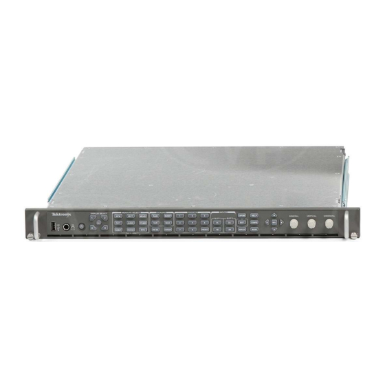
Page 31: Figure 3: Front Panel
1. Press and hold the PRESET button. 2. Use the GENERAL knob to navigate to Recall Preset. 3. Press the right and down arrow keys to navigate to Recall Factory Preset and press the SEL button. WVR8200, WVR8300 User Manual... -
Page 32: Figure 4: Instrument Online Help
9. Press the HELP button to exit help. Fan Test You should be able to hear the fans and feel air coming out of the back of the instrument. At low temperatures, the fans will turn slowly and be very quiet. WVR8200, WVR8300 User Manual... -
Page 33: Getting Acquainted With Your Instrument
SELECT button for about a second. Instrument-wide settings. The parameters in the Configuration menu are instrument-wide settings. The configuration menu controls settings that are changed only occasionally, such as changing waveform color or setting the network address. WVR8200, WVR8300 User Manual... - Page 34 Measurement buttons How to select a display using the Measurement buttons (See page 33.) Gain and Sweep buttons How to use Gain, Sweep, and Magnification (See page 89.) Preset buttons How to use Presets (See page 93.) WVR8200, WVR8300 User Manual...
- Page 35 Access to waveform, graticule, LCD backlight intensity, display capture to USB, and Infinite Persistence mode. Main button Access to Multi-Input Display mode, SyncVu mode, SIM mode, and USB status. Other button Access to the LTC Display (See page 50.) WVR8200, WVR8300 User Manual...
-
Page 36: Remote Front Panel Control
Getting Acquainted With Your Instrument Remote Front Panel Control This instrument can be controlled remotely by the Tektronix WVR8RFP remote front panel, an optional accessory. The remote front panel functions just like the instrument front panel, with just a few differences. For detailed installation and operation information, see the WVR8RFP Remote Front Panel Instructions. -
Page 37: Instrument Display
Activate one of the four tiles by pressing a numbered Display Select button. The active tile is outlined in blue and the numbered button associated with that tile is lit. (See Figure 5.) Figure 5: Display Select buttons WVR8200, WVR8300 User Manual... -
Page 38: Figure 6: Full Button Function
Figure 8.) When a single input is being monitored, the status bar shows the type of signal, any alarms associated with that signal, and other information. (See Figure 7.) Figure 7: Status bar in single input mode WVR8200, WVR8300 User Manual... -
Page 39: Figure 8: Status Bar In Simultaneous Input Mode
Text indicating the selected input. Some possible inputs are: SDI 1A, SDI 2A, SDI 1B, SDI 2B, Cmpst 2A, and Cmpst 2B (depending on installed options). Also indicates if the current input is not in Auto mode or is unlocked. WVR8200, WVR8300 User Manual... - Page 40 Freeze Active - Appears when the tiles are frozen or captured. Rear Panel Specifications See the WVR8200 and WVR8300 Waveform Rasterizers Safety and Installation Instructions that shipped with your instrument for rear panel specifications. It is also available in electronic format on the Product Documentation CD and on the Web at www.tektronix.com/manuals.
-
Page 41: Signal Inputs
(See Figure 9.) (See Figure 10.) (See Figure 11.) NOTE. You can connect up to four SDI signals to an instrument with Option 2SDI. This option allows you to add a second SDI module into Slot 2 of the instrument rear panel. WVR8200, WVR8300 User Manual... -
Page 42: Figure 9: Single Sdi Signal Connection
Signal Inputs Figure 9: Single SDI signal connection Figure 10: Two SDI signal connection WVR8200, WVR8300 User Manual... -
Page 43: Composite Signals
This monitoring connection checks the performance of the entire path. The return loss of the instrument is sufficiently high that, in most cases, the destination receiver sets the system return loss. WVR8200, WVR8300 User Manual... -
Page 44: Dual Link Signals
Dual link signals are combined in the instrument and then shown as a single signal on a waveform or other display. (See Figure 13.) Figure 13: Dual Link signal connection WVR8200, WVR8300 User Manual... -
Page 45: Multi-Input Display Mode
MAIN button menu. To enable this feature: 1. Press and hold the MAIN button. 2. Navigate to Multi-Input Mode. 3. Press the SEL button to highlight Enable. 4. Press the MAIN button to dismiss the menu. WVR8200, WVR8300 User Manual... - Page 46 2SDI, pressing the 1B, 2A, or 2B input buttons will give you the same menu options as follows, but with different labels. NOTE. You can customize the input labels. (See page 29, To Customize Input Labels.) WVR8200, WVR8300 User Manual...
-
Page 47: Figure 15: Waveform Display In Multi-Input Mode Showing Multiple Channels
You can name the input labels from the CONFIG > Graticules and Readouts > Input Labels menu. Once you are in the Input Labels menu, select an input and then press the SEL button. A dialog box will appear allowing you to name the input. WVR8200, WVR8300 User Manual... -
Page 48: Simultaneous Input Monitoring
This monitoring connection checks the performance of the entire path. The return loss of the instrument is sufficiently high that, in most cases, the destination receiver sets the system return loss. WVR8200, WVR8300 User Manual... -
Page 49: Signal Generation
Figure 17.) Three types of signals can be generated in Level A and Level B: 75% bars 100% bars Pathological For more information about these signals, see the appropriate SMPTE standard. Figure 17: Signal generation connection WVR8200, WVR8300 User Manual... - Page 50 After you have connected the signals, press the CONFIG button on the front panel of the instrument and navigate to the Outputs submenu. From this submenu, select the test signal pattern, level, and format you want to generate. WVR8200, WVR8300 User Manual...
-
Page 51: Display Information
STATUS: display of extensive views of signal status MEAS: display of various measurements, including timing, audio video delay, ANC data, and Data List. EYE: display of the eye pattern and jitter of a signal OTHER: display of the Longitudinal Time Code (LTC) WVR8200, WVR8300 User Manual... -
Page 52: Figure 18: Using The Display Select Buttons
3. Use the right and left keys to traverse between menu panels. The instrument surrounds the panel selected with a blue border. (See Figure 19.) 4. Use the up and down arrow keys to select parameters in a menu. (See Figure 19.) WVR8200, WVR8300 User Manual... -
Page 53: Waveform Display
3. This readout lists the currently selected field and line (when in Line Select mode). 4. This readout lists the current sweep rate for tile. 5. This readout lists the Mag rate if MAG is on. WVR8200, WVR8300 User Manual... - Page 54 Composite input; it shows two waveforms in parade configuration. NOTE. For SDI displays, such as RGB mode, the available filters are Flat and Low Pass. For Composite displays, the available filters are Flat, Luma, Chroma, and Flat+Luma. WVR8200, WVR8300 User Manual...
-
Page 55: Vector Display
The VECT button calls up the Vector and Lightning displays, which provide for selection between two plots of the color portions of the signal. (See Figure 20.) (See Figure 21.) Figure 20: Vector display with Luma Qualified Vector (LQV) enabled WVR8200, WVR8300 User Manual... -
Page 56: Figure 21: Lightning Display
If you have Option PROD installed, you can also select to turn Luma Qualified Vector On or Off. When it is on, you can set luma high and luma low parameters WVR8200, WVR8300 User Manual... - Page 57 This is a Tektronix proprietary display and is for SDI signals only.
-
Page 58: Gamut Display
Gamut Display Pressing the GAMUT button calls one of the Gamut displays. The Gamut display provides four proprietary Tektronix display types to enable you to check the gamut of an SDI signal. Set the thresholds for gamut displays from the CONFIG menu. - Page 59 Display Information Spearhead: shows lightness, color value, and saturation of the RGB color space (requires Option PROD) Diamond: provides a reliable method of detecting invalid colors WVR8200, WVR8300 User Manual...
- Page 60 GAMUT display, use the pop-up menu to select from the following displays: Diamond shows Gamut violations of the SDI input if translated to RGB color space. Split Diamond offsets the two halves of the Diamond to allow you to better see negative RGB Gamut errors. WVR8200, WVR8300 User Manual...
-
Page 61: Timing Display
(See page 27, Multi-Input Display Mode.) Timing Display Pressing the MEAS button displays a Tektronix proprietary display that simplifies measuring the timing difference between two signals as the timing is corrected. Using the Timing display enables you to easily compare and correct the timing between two signals. - Page 62 Save Offset menu entry. This selection changes both the numeric readouts and the target in the middle of the timing display. WVR8200, WVR8300 User Manual...
-
Page 63: Figure 23: Timing Display Of Integer Multiples Of Reference Rates
Such cases include timing an NTSC input (multiplier of 1) or a 525 SDI input whose frame time is 33.36 ms (multiplier of 2), against an NTSC reference, which has a frame time of 66.73 ms. WVR8200, WVR8300 User Manual... -
Page 64: Figure 24: Timing Display Of Non-Integer Multiples Of Reference Rates
fields of the input and five frames of the reference. Because this allows for five possible ways to measure timing between these two signals, the timing display shows four circles, with emphasis and readouts as previously described above. WVR8200, WVR8300 User Manual... -
Page 65: Datalist Display
Word Select: Shows which word is selected; press the SEL button to switch between Line Select and Word Select Samp#: Shows the sample number Y0, Cb, Cr, Y1: These labels change based on the signal, but they show the line number for each component WVR8200, WVR8300 User Manual... - Page 66 8 or 10-bit values. Format: Select from Hexidecimal, Decimal, or Binary. (Default is Hexidecimal.) Link Selection: Select from Link A, Link B, or Dual Link. This menu item is only available when the trace type is Data. WVR8200, WVR8300 User Manual...
-
Page 67: Bowtie Display
Y-axis units: The units for the y-axis depend on the test signal and the signal format. X-axis units: Shows the x-axis in microseconds/divisions. Bowtie Display Pop-up Parade / Overlay: Select how the waveform appears by selecting Parade or Overlay. Menu Center Waveform: Press the SEL button to center the waveform. WVR8200, WVR8300 User Manual... -
Page 68: Ltc Display
The REMOTE connector is a 15-pin D-type connector with socket contacts. For pin information, see the Safety and Installation manual or the System Integration manual on the Product Documentation CD that shipped with your instrument and the Web at www.tektronix.com/manuals. Figure 27: LTC display Elements of the LTC Display: Shows the display type as LTC. -
Page 69: Ancillary (Anc) Data Display
SDID: Secondary Data Identifier of the requested packet; permissible values range from 0 through 0xFF (255) inclusive; this field only appears when a Type 2 packet is selected; the "actual value" (with parity bits added) is displayed in parentheses (mutually exclusive with DBN field) WVR8200, WVR8300 User Manual... - Page 70 6. Press the CONFIG button to dismiss the menu. 7. Press and hold the MEAS button and select Display Type and then ANC Data Display from the pop-up menu. You can now view the data types you checked in the Watch List. WVR8200, WVR8300 User Manual...
-
Page 71: Audio Video Delay (Avd) Display
AVD allows you to take measurements and display them in both numeric and graphical formats. AVD measurements require an appropriate AVD sequence signal source, such as from a Tektronix TG700 signal generator. This capability is useful for facility maintenance and setup applications because it allows for out-of-service testing to quickly check synchronization across a facility. -
Page 72: Eye Display
Eye waveform. (See Figure 31.) NOTE. See Monitoring the SDI Physical Layer for information about taking Eye measurements. (See page 101.) Figure 30: Eye display in 4-tile mode (no histogram) WVR8200, WVR8300 User Manual... -
Page 73: Figure 31: Eye Display In Single Tile Mode (Full-Screen) With Histogram
Jitter. It allows you to do the following: Jitter1 HP Filter: Select the HP filter to be Timing, Align, 10 Hz, 100 Hz, 1 kHz, 10 kHz, or 100 kHz. Center Waveform: Press the SEL button to center the waveform. WVR8200, WVR8300 User Manual... - Page 74 If the equalized eye display appears clear with a substantial eye opening, then the signal is likely to be recovered error-free. However, if it appears noisy with little eye opening, then there is more potential for data errors to occur in the receiver. WVR8200, WVR8300 User Manual...
-
Page 75: Jitter Display
You can also set alarms on various parameters. (See page 109, To Make Jitter Measurements.) Figure 32: The Jitter display parameters as shown in a single tile when the instrument is in 4-tile mode WVR8200, WVR8300 User Manual... -
Page 76: Figure 33: The Jitter Display Parameters As Shown When The Instrument Is In Single-Tile Mode
This shape is modified by the high-pass filter (HPF) setting. Display Jitter Thermometer: Displays jitter value and relates it to alarm limits. Jitter HPF: Indicates the setting for the Jitter High Pass Filter, set in the CONFIG menu. WVR8200, WVR8300 User Manual... - Page 77 10 Hz, 100 Hz, Sets the detector high-pass filter to the selected value. 1 kHz, 10 kHz, 100 kHz NOTE. For instructions on how to take jitter measurements, see Monitoring the SDI Physical Layer. (See page 101.) WVR8200, WVR8300 User Manual...
-
Page 78: Status Displays
Date: Shows the date, according to the internal clock, that the error occurred. The date is displayed as month/day/year. Page: Shows which page you are viewing out of the total number of pages in the log. WVR8200, WVR8300 User Manual... - Page 79 Save to USB (ALL): Saves the entire unfiltered error log to a USB memory device. Save to USB (Sel.): Saves only the errors in the error log for the selected channel or input to a USB memory device. WVR8200, WVR8300 User Manual...
-
Page 80: Figure 35: Alarm Status Display
(red). Gray indicates the alarm is not being logged but still provides information on the function. Additional Information: Provides explanatory information about the error, if available. Alarm Status pop-up menu. Mute Alarms mutes alarms for all Status display types. WVR8200, WVR8300 User Manual... -
Page 81: Figure 36: Video Session Display Of Hd Signal
The displayed values are either Present or None for SD signals, or Y and C Present and None for HD and 3 Gb/s signals. F1 AP CRC: For SD signals only, calculates and displays the active picture CRC (Cyclical Redundancy Check) for field one in hexadecimal. The WVR8200, WVR8300 User Manual... - Page 82 Err Fields: The number of fields, since the last reset, that contained at least one error. % Err Fields: Shows a calculated number showing the percentage of all fields since the last reset that contained at least one error. WVR8200, WVR8300 User Manual...
- Page 83 All Sessions Stop: Globally stops any and all stopped video sessions displayed in all panes, regardless of the display and session from which it is executed. WVR8200, WVR8300 User Manual...
-
Page 84: Figure 37: Audio Session Display
Over: The number of OVERs detected during the session. (Only displayed for digital audio feeds.) Loud: The number of times the Analog Audio or Digital Audio loudness alarms have been trigger during the current session. Mute: The number of MUTEs detected during the session. WVR8200, WVR8300 User Manual... - Page 85 It is commonly referred to as the "short" loudness average. Short Pd: The Short Period defines the duration of the short Loudness average and is defined by the user within the Config menu for Loudness Settings. WVR8200, WVR8300 User Manual...
- Page 86 All Sessions Stop: Globally stops any and all stopped audio sessions displayed in all panes, regardless of the display and session from which it is executed. WVR8200, WVR8300 User Manual...
- Page 87 Channel Summation: Shows the summation of audio channels currently used to compute the loudness average. Target Value: Shows the currently defined Target Loudness level. Loudness Session Time: Shows the current duration of the loudness session since last reset. WVR8200, WVR8300 User Manual...
- Page 88 History Reset: Resets the audio loudness session history. All Sessions Reset: Globally resets any and all audio and video sessions displayed in all panes, regardless of the display and session from which it is executed. WVR8200, WVR8300 User Manual...
- Page 89 For HD signals, the audio control packet carries additional information used in the process of decoding the audio data and has a similar structure to standard definition. The elements of the Audio Packet display vary depending on the monitored signal. (See Figure 41.) WVR8200, WVR8300 User Manual...
- Page 90 file in your instrument: while the Audio Control display is active in a tile, press the HELP button and follow the link at the bottom of the page to Audio Control Packet Display Elements. WVR8200, WVR8300 User Manual...
- Page 91 Active Chan: Shows whether the audio channel is active or inactive. Delay Samples: Shows the amount of accumulated audio processing delay relative to video, measured in audio sample intervals. Audio Control Pop-up Menu. Mute Alarms mutes alarms for all Status display types. WVR8200, WVR8300 User Manual...
- Page 92 608 and 708 packets. Note that packet 608 typically has 4 data words and packet 708 has up to 46 data words, depending on the frame rate as defined in SMPTE 334. WVR8200, WVR8300 User Manual...
- Page 93 6 to Bits 3 that are used to define the Active Format Descriptor. Conforms to SMPTE RP186-2008 Class 1.1. or ARDSPEC 1. See the instrument online help for a detailed description of codes: while the Aux Data Status display is active in a tile, press the HELP button. WVR8200, WVR8300 User Manual...
- Page 94 Program Configuration: Determines how the audio channels are grouped within a Dolby E bitstream. Up to eight channels can be grouped together in individual programs, where each program contains its own metadata. WVR8200, WVR8300 User Manual...
- Page 95 To view the ARIB content displays, enable this option in CONFIG > Aux Data Settings > ARIB Content Display. For detailed information about ARIB displays, go to the ARIB Displays section in this manual. (See page 125.) WVR8200, WVR8300 User Manual...
- Page 96 Approx Cable: Shows the approximate length of cable, assuming a continuous run of cable of the specified type, as specified in the Cable Type field of the Physical Layer Settings selection available from the CONFIG button. WVR8200, WVR8300 User Manual...
- Page 97 Jitter1 HP Filter: Select the filter type: Timing, Align, 10 Hz, 100 Hz, 1 kHz, 10 kHz, 100 kHz Jitter2 HP Filter: Select the filter type: Timing, Align, 10 Hz, 100 Hz, 1 kHz, 10 kHz, 100 kHz WVR8200, WVR8300 User Manual...
-
Page 98: Audio Display
Phase, Surround, or Loudness Display: Select between the Phase display, where the phase of a selected pair of channels is plotted against an X-Y or sound-stage plot; and the Surround display, where all the channels levels WVR8200, WVR8300 User Manual... - Page 99 NOTE. The loudness measurement supports three types of filters: Flat, A-weighted, and RLB (ITU-R BS.1770). The measurement can be viewed in the Audio Session display and configured in the Audio pop-up menu. WVR8200, WVR8300 User Manual...
- Page 100 DOLBY D. Indicates an AES or embedded input is Dolby Digital. DOLBY D+. Indicates an AES or embedded input is DOLBY Digital Plus. DOLBY E. Indicates an AES or embedded input is DOLBY E. WVR8200, WVR8300 User Manual...
- Page 101 A-weighted, results in a response that more closely matches that of the human ear. NOTE. The Audio Surround Sound display is courtesy of Radio-Technische Werkstaetten GmbH & Co. KG (RTW) of Cologne, Germany. Surround Sound: Radio-Technische Werkstaetten GmbH & Co. WVR8200, WVR8300 User Manual...
- Page 102 fixed for 16-Channel audio. Selecting Audio Input for 1. Select a tile. Embedded 16-Channel 2. Press and hold the Audio button to open the Audio display in a tile and pop Audio up the Audio menu. WVR8200, WVR8300 User Manual...
- Page 103 2. Press and hold the Audio button to open the Audio display in a tile and pop Embedded Audio up the Audio menu. 3. Use the arrow keys and SEL button to make selections in the steps that follow. 4. Select Audio Input and then select Emb. 1-8 or Emb. 9-16. WVR8200, WVR8300 User Manual...
-
Page 104: Picture Display
Picture Frame, VChip, Closed Captioning (CC), Teletext, and Safe Area Graticules. (See Figure 47.) (See page 159, Closed Captioning (CC), Teletext, AFD, and Safe Area Compliance.) Figure 47: Picture display showing color bars WVR8200, WVR8300 User Manual... - Page 105 TeletextB OP47 Multi (ANC) For HD and 3G: CEA-608 (ANC), CEA-608 (708), CEA-708, TeletextB VBI, TeletextB OP47 SDP (ANC), and TeletextB OP47 Multi (ANC) Figure 48: VChip, CC-Display, Teletext, and Safe Area Graticule in Picture display WVR8200, WVR8300 User Manual...
- Page 106 Safe Area Title 2: Select from Off, Auto, 4x3, 14x9, 16x9, Custom_1, and Custom_2 Black/Frozen Grat: Select from Off, Black, and Frozen AFD Graticules: Select from ON and Off Picture Center Grat: Select from ON and Off WVR8200, WVR8300 User Manual...
-
Page 107: Functions
Press and hold the MAG button to display the Magnification pop-up menu. Select a magnification setting, such as Best View, x10, x20, x25, or x30. In the Vector displays, the magnification is called H Gain (horizontal gain). The available options depend on which display is active. WVR8200, WVR8300 User Manual... -
Page 108: Cursors
NOTE. To quickly center the active cursor on screen, press and hold the SEL button. 5. Repeat steps 2 through 4 to adjust the other cursor. 6. Read the cursor measurement in the Cursors readout. WVR8200, WVR8300 User Manual... -
Page 109: Capture
For waveform displays, the captured image is shown in a different color to distinguish it from the live image. For all displays, the instrument continues to log error status in the background while the display is captured. WVR8200, WVR8300 User Manual... -
Page 110: Line Select
Figure 50: Navigating line selection Headphone Volume and Source Adjustment WARNING. To avoid damaging your hearing, always turn the volume down to the minimum before you put on headphones, and then turn the volume up slowly. WVR8200, WVR8300 User Manual... -
Page 111: Presets
The following is an overview of the settings saved in a Preset. Measurement assigned to each tile Tile specific settings Input selection SDI Input settings Composite Input settings External Reference settings Audio Displays settings Audio Inputs/Outputs settings Alarm settings Gamut thresholds Display settings Readout setting Graticule settings WVR8200, WVR8300 User Manual... - Page 112 SEL button. To recall factory presets, press the PRESET button to display the Preset Menu. Use the arrow buttons to navigate to Recall Preset > Recall Factory Preset and then press the SEL button. WVR8200, WVR8300 User Manual...
- Page 113 Functions Importing Presets from a You can also save presets to the USB drive so that you can load them on multiple WVR8200 or WVR8300 instruments in your system. To import presets to a USB USB Device memory device: 1. Insert a USB memory device into the USB drive located in the front of the instrument.
-
Page 114: Software Upgrades
Installation procedure. Obtain the Latest Software Download the latest version of software available for your instrument. 1. Use the Web browser on the PC to navigate to the following Tektronix Web site: http://www.tektronix.com/downloads 2. On the Downloads Web page, search by model number (for example, WVR8300) and filter software and software type to locate the latest... - Page 115 Do not remove the USB device until the upgrade is complete. Network Software Use the following steps to upgrade the instrument software using a network connection. Installation 1. Connect the instrument and PC to your local Ethernet network. 2. Power on the instrument. WVR8200, WVR8300 User Manual...
- Page 116 4. Prepare the instrument for the software upgrade: a. Press the CONFIG front panel button. b. Navigate to Utilities > System Upgrade > Upgrade Options > Network Upgrade. c. Press the SEL front panel button. This displays the System Software Upgrade window. WVR8200, WVR8300 User Manual...
- Page 117 2. Press the CONFIG button on the front panel. 3. Navigate to Utilities > View HW/SW Version. 4. Verify that the software version number matches the version of the software-upgrade package you installed. WVR8200, WVR8300 User Manual...
- Page 118 Functions WVR8200, WVR8300 User Manual...
-
Page 119: Monitoring The Sdi Physical Layer
With Option PHY installed, this display also shows the eye amplitude, eye risetime, eye falltime, eye risetime overshoot, eye falltime overshoot, and eye rise-fall delta measurement values. (See page 78, SDI Status.) WVR8200, WVR8300 User Manual... -
Page 120: Configuring Physical Layer Settings
11. Select one of the following settings: Normal. The Eye display shows the SDI input signal directly. Equalized. The Eye display shows the SDI input signal after it has passed through the internal cable equalizer and comparator. WVR8200, WVR8300 User Manual... -
Page 121: To Set Smpte 259/292/425 Alarm Thresholds
30.0 dB; the minimum level is 0.0 dB. 9. Select Cable Length to specify the threshold for the length of the cable (in meters) connecting the signal source to the instrument. WVR8200, WVR8300 User Manual... -
Page 122: To Configure Physical Layer Alarms
You can read more about alarms in the Configuring Alarms section. 1. From the CONFIG menu, select Alarms > Physical Layer. 2. Press the SEL button. 3. Use the arrow keys and the SEL button to mark the squares for the alarms you want to monitor. WVR8200, WVR8300 User Manual... -
Page 123: To Make Eye Measurements
4. Position one voltage cursor at the top part of the waveform, ignoring any overshoot or undershoot on the rising or falling edges. (See Figure 52.) 5. Note the amplitude of the eye waveform that is displayed in the Voltage Cursor readout. (See Figure 52.) WVR8200, WVR8300 User Manual... - Page 124 (See Figure 53.) 5. Note the amplitude of the aberration displayed in the Voltage Cursor readout. (See Figure 53.) 6. Perform the same voltage-cursor measurement on the bottom line thickness, including any undershoot and ringing. WVR8200, WVR8300 User Manual...
- Page 125 6. Position the second time cursor at the crossing of the rising edge of the Eye waveform and the graticule line two divisions below the top of the waveform. (See Figure 54.) 7. Note the 20 – 80% rise time measurement displayed in the Delta time readout. (See Figure 54.) WVR8200, WVR8300 User Manual...
- Page 126 4. Note the Eye waveform measurements in the SDI Status display readouts. Automatic Eye measurements (and a histogram of the Eye waveform) are also displayed in the Eye Waveform display when expanded to the single, full-screen display. WVR8200, WVR8300 User Manual...
-
Page 127: To Make Jitter Measurements
This jitter is from a sine wave component. Notice that there is no indication of jitter spikes. In the lower Eye display, the jitter is of a low-density haze, which suggests a less uniform jitter distribution. This is indicated by the spikes. WVR8200, WVR8300 User Manual... - Page 128 To measure timing jitter, select the 10 Hz filter for both SD and HD signals, or select the Timing filter. To measure alignment jitter, select the 1 kHz filter for SD signals or select the 100 kHz filter for HD signals, or select the Align filter. WVR8200, WVR8300 User Manual...
- Page 129 Alignment jitter (100 kHz filter): 134 ps (0.2 unit intervals). 3 Gb/s Signals (per SMPTE 425M) Timing jitter (10 Hz filter): 336 ps (1.0 unit intervals). Alignment jitter (100 kHz filter): 67 ps (0.2 unit intervals). WVR8200, WVR8300 User Manual...
-
Page 130: Taking Cable Loss Measurements
3. Press and hold the STATUS button to display the pop-up menu. 4. Use the arrow keys and the SEL button to select the SDI Status display. 5. Use the Cable Loss thermometer and readouts to monitor the cable loss. (See Figure 57.) WVR8200, WVR8300 User Manual... -
Page 131: Alarms
SNMP Trap. The instrument sends an SNMP trap out the Ethernet port for a remote notification that an alarm condition occurred. You must enable and configure the instrument for SNMP control using the Network Settings submenu of the Configuration menu before SNMP traps can be sent. Refer WVR8200, WVR8300 User Manual... - Page 132 5. Navigate to highlight the Return box, and press the SEL button to return to the Configuration menu. To Enable Alarms The channels for which you enable alarms trigger your previously defined alarm responses. (See page 114, To Set Allowed Alarm Responses.) WVR8200, WVR8300 User Manual...
- Page 133 4. Select the required services for the desired CC type and select the CC channels and/or Text channels for which you want to trigger the CC Services Missing Alarm. 5. For SDI Gamut display related alarms, select Gamut Thresholds and then the desired gamut thresholds. WVR8200, WVR8300 User Manual...
- Page 134 To monitor alarms remotely, use a PC to monitor SNMP traps over the Ethernet port (the PC must have SNMP trap service installed). Before SNMP traps can be sent, you must enable and configure the instrument for SNMP control using the Network Settings submenu of the Configuration menu. WVR8200, WVR8300 User Manual...
-
Page 135: Checking Chroma/Luma Delay (Lightning Display)
Alignment to a mark toward white means the color-difference signal leads the luma signal. The upper half of the display measures the Pb to Y timing; the bottom half measures the Pr to Y timing. WVR8200, WVR8300 User Manual... - Page 136 The + tic marks on the graticule indicate the following timing errors: 1080p 50, 59.94, 60, 3Gbps (3 Gb/s and dual link formats) Timing Error Tic Mark SD Timing Error (ns) HD Timing Error (ns) (ns) 0 marks 13.5 6.75 13.5 Luma sample Chroma sample WVR8200, WVR8300 User Manual...
-
Page 137: Checking Gamut
3. In the Gamut pop-up menu, select of the following gamut display types: Diamond – Use to detect, isolate, and correct RGB component gamut errors. (See page 120, Checking RGB Gamut.) Split Diamond – Use to reveal hard-to-find black gamut errors. WVR8200, WVR8300 User Manual... -
Page 138: Checking Rgb Gamut
The direction of an excursion out of gamut indicates which signal is excessive. Errors in green amplitude affect both diamonds equally, while blue amplitude errors affect only the top diamond and red errors affect only the bottom diamond. (See Figure 59.) Figure 59: Diamond display plot WVR8200, WVR8300 User Manual... - Page 139 B < 0 mV Figure 60: Out-of-gamut examples Usage Notes As with the lightning display, bending of the transitions indicates timing delays. When a color bar signal is applied, the vertical axis becomes an indicator of delay errors. WVR8200, WVR8300 User Manual...
-
Page 140: Checking Composite Gamut
Arrowhead displays (75% Color bars) and indicates the values of the graticule lines. The arrowhead shape of the graticule results from overlaying the standard limits for luminance and luminance-plus-peak chrominance. (See Figure 61.) Figure 61: Arrowhead gamut display plots WVR8200, WVR8300 User Manual... -
Page 141: Checking Luma Gamut
You can use alarms to automatically monitor for out-of-gamut conditions. 1. Check that Gamut thresholds are configured as you want them. (See page 119, To Set Up Gamut Checks.) 2. Press the CONFIG button to display the Configuration menu. WVR8200, WVR8300 User Manual... - Page 142 5. When you have configured the Alarms as you want them, move to the Select here box and select it. 6. Back in the Alarms menu, check that Enable Alarms is set to On before exiting the Alarms menu. WVR8200, WVR8300 User Manual...
-
Page 143: Arib Displays
ARIB STD-B.35 Trigger Signal for Data Broadcasting 0x5F 0xFD ARIB STD-B.37 Closed Captioning 0x5F 0xDD Analog signal 0x5F 0xDE SD signal 0x5F 0xDF HD signal ARIB STD-B.39 Inter Stationary Control Data 0x5F 0xFE ARIB specification 0x43 0x01 ITU specification WVR8200, WVR8300 User Manual... -
Page 144: Arib Status
ARIB STD-B.37 (closed caption data) ARIB STD-B.35 (trigger signal data) ARIB TR-B.23 (1) (guidelines for inter-stationary control data transport, group 1) ARIB TR-B.23 (2) (guidelines for inter-stationary control data transport, group 2) ARIB TR-B.22 (guidelines for ancillary data transport) WVR8200, WVR8300 User Manual... -
Page 145: Arib Std-B.39 Display
ARIB STD-B.39 packets using the DID/SDID combinations defined by either the ITU or ARIB standards organizations. Figure 63: ARIB STD-B.39 display (with the associated ARIB Status display) WVR8200, WVR8300 User Manual... - Page 146 254 (0xFE). A value of 0xFF indicates that no format change is pending within the next several seconds. Current Downmix/Audio Mode - Indicates the audio downmix and soundstage configuration of the current program. WVR8200, WVR8300 User Manual...
- Page 147 Status Bits (S8..S1 S16..S9) - 16 user-defined status bits. Error Correcting Code - A six-word, Reed-Solomon error correcting code, which is used to verify the integrity of the ARIB B.39 or ITU-R BT.1685 packet. WVR8200, WVR8300 User Manual...
-
Page 148: Arib Std-B.37 Display And Status Screens
ARIB STD-B.37. (See Figure 64.) When this display is selected, the instrument searches the signal for ARIB STD-B.37 packets using the DID/SDID combinations defined by ARIB. Figure 64: ARIB STD-B.37 display (with the associated ARIB Status display) WVR8200, WVR8300 User Manual... - Page 149 ECC Status - Indicates the presence or absence of the Error Correcting Code information in the payload. Format ID - Indicates whether the packet is for HD, SD, Analog, or Mobile captions. Language - Indicates the language code (1st through 8th) of the packet. WVR8200, WVR8300 User Manual...
- Page 150 Checksum - Indicates the checksum word that was recovered from the acquired packet. Placement - Can display either OK or ERROR, indicating whether the ARIB B.37 packets are present in the allowable configuration(s) specified in ARIB TR-B.23. WVR8200, WVR8300 User Manual...
-
Page 151: Arib Std-B.35 Display And Status Screens
SDID - Secondary Data Identifier of the requested packet; permissible values range from 0 through 0xFF (255) inclusive. This field only appears when a Type 2 packet is selected (see above). The actual value (with parity bits added) is displayed in parentheses. WVR8200, WVR8300 User Manual... - Page 152 Should be - Indicates the checksum word computed by the instrument, based on the packet data. Format - Indicates the name of the ancillary data type or standard. User Data Words - Contains the payload of the ancillary packet, displayed in hexadecimal. Displays all 10 bits. WVR8200, WVR8300 User Manual...
-
Page 153: Arib Tr-B.23 (1) Display And Status Screens
SDID - Secondary Data Identifier of the requested packet; permissible values range from 0 through 0xFF (255) inclusive. This field only appears when a Type 2 packet is selected (see above). The actual value (with parity bits added) is displayed in parentheses. WVR8200, WVR8300 User Manual... - Page 154 Should be - Indicates the checksum work computed by the instrument, based on the packet data. Format - Indicates the name of the ancillary data type or standard. User Data Words - Contains the payload of the ancillary packet, displayed in hexadecimal. Displays all 10 bits. WVR8200, WVR8300 User Manual...
-
Page 155: Arib Tr-B.23 (2) Display And Status Screens
SDID - Secondary Data Identifier of the requested packet; permissible values range from 0 through 0xFF (255) inclusive. This field only appears when a Type 2 packet is selected (see above). The actual value (with parity bits added) is displayed in parentheses. WVR8200, WVR8300 User Manual... - Page 156 Should be - Indicates the checksum work computed by the instrument, based on the packet data. Format - Indicates the name of the ancillary data type or standard. User Data Words - Contains the payload of the ancillary packet, displayed in hexadecimal. Displays all 10 bits. WVR8200, WVR8300 User Manual...
-
Page 157: Arib Tr-B.22 Display And Status Screens
SDID - Secondary Data Identifier of the requested packet; permissible values range from 0 through 0xFF (255) inclusive. This field only appears when a Type 2 packet is selected (see above). The actual value (with parity bits added) is displayed in parentheses. WVR8200, WVR8300 User Manual... - Page 158 Should be - Indicates the checksum work computed by the instrument, based on the packet data. Format - Indicates the name of the ancillary data type or standard. User Data Words - Contains the payload of the ancillary packet, displayed in hexadecimal. Displays all 10 bits. WVR8200, WVR8300 User Manual...
-
Page 159: Audio Monitoring
8. In the dialog box that appears, select which inputs (if any) to route to the analog outputs. 9. Select the box to return to the Configuration menu. 10. Repeat these sets for any other Audio inputs. WVR8200, WVR8300 User Manual... -
Page 160: Selecting Audio Inputs
Each bar displays three colors. (See Figure 69.) Green – Indicates audio levels below the test level Yellow – Indicates audio levels between the test and peak program level Red – Indicates audio levels above the peak program level WVR8200, WVR8300 User Manual... - Page 161 For uncorrelated signals, the indicator is yellow and tends to stay in the middle. For anticorrelated signals (one goes up when the other goes down), the indicator is red and moves to the left side. WVR8200, WVR8300 User Manual...
- Page 162 X-Y display of an oscilloscope. The following response times of the correlation meters can be set from the Configuration menu. Response averaging time Response averaging time Speed Speed setting setting 0.0167 0.0333 0.0667 0.1333 0.2667 0.5333 8 (default) WVR8200, WVR8300 User Manual...
-
Page 163: To Check Surround Sound
6. Use the level bar display to monitor level control. (See page 142, To Check Audio Level.) 7. Use the surround display to monitor relative loudness of the individual elements rendered in a surround-sound listening environment. Check the surround sound display for performance parameters and indicators. (See Figure 71.) WVR8200, WVR8300 User Manual... - Page 164 Channel-Pair Phantom Sound Indicators (PSIs) – located on each side of the Surround Sound display, indicates the location of potential phantom sound sources formed by adjacent channels. The white tic marks on these moving bar indicators show the phantom source locations. The bar length indicates WVR8200, WVR8300 User Manual...
- Page 165 Like the L-R PSI, the bar continues to grow at a 45° angle for negative signal correlations. The bar to the right of the white tic mark behaves similarly, depending on the C-R correlation. This PSI indicator uses the same color coding as the other PSI indicators. WVR8200, WVR8300 User Manual...
- Page 166 Surround sound program with strong center channel presence. Surround sound program with weak center channel presence. Monaural signal in channels Ls and Rs, creating a phantom source in the center, as in a 3.1 surround sound system. WVR8200, WVR8300 User Manual...
-
Page 167: To Monitor Dolby Based Surround Sound
(The AES B bank must be configured as outputs.) NOTE. When a Dolby input is active, channel labels (L, R, Ls, and so on) appear in addition to the channel numbers. WVR8200, WVR8300 User Manual... - Page 168 4. Choose Full or a mode to which you want to downmix. NOTE. Dolby content of the signal at the Dolby input must be sufficient to downmix to the mode selected or the setting has no effect. 5. Select Dialnorm&DynRng. WVR8200, WVR8300 User Manual...
- Page 169 Figure 72: Dolby surround sound display 13. View the Dolby Guardband thermometer, which is located at the bottom of the Audio display. The thermometer is green for levels that fall within the limits you have set. (See Figure 45.) WVR8200, WVR8300 User Manual...
- Page 170 Dolby Pro-Logic compatible stereo mix. To Display Dolby Inputs After you have configured a Dolby input, you can display its levels and other characteristics in the Audio Display. (See page 149, To Configure Dolby Inputs.) WVR8200, WVR8300 User Manual...
- Page 171 Dolby Display Readout The Dolby Display readout shows the following. (See Figure 74.) 1. The selected Dolby input. 2. The selected Dolby Source for the input. 3. The Coding (Channel) Mode. 4. The Listening Mode setting. WVR8200, WVR8300 User Manual...
- Page 172 Audio Display level bars. (See Table 6 on page 156.) Basic Listening Modes EX. Use EX if the two surround channels have been matrix encoded with a back channel. If the EX listening mode is selected and there are two surround WVR8200, WVR8300 User Manual...
- Page 173 A 2/0 encoded Dolby stream is assumed to be Pro Logic encoded already and is Pro Logic decoded to produce a LCR output. Any PCM input is decoded to provide LCRS channels where the surround channel is reduced 3 dB and reproduced in both the Ls and Rs bars. WVR8200, WVR8300 User Manual...
-
Page 174: Table 6: Channel Mode Versus Listening Modes
S mixed into L and R with smix coefficient Phantom C mixed into L and R with cmix coefficient Stereo Lo/Ro downmix Mono Lo+Ro PL Full LCRS from Lt/Rt downmix PL 3 Stereo 3 Stereo from Lt/Rt PL Phantom Phantom from Lt/Rt WVR8200, WVR8300 User Manual... - Page 175 Default to Mono mode Phantom Default to Mono mode Stereo Default to Mono mode Mono Mono center channel output PL Full Default to Mono mode PL 3 Stereo Default to Mono mode PL Phantom Default to Mono mode WVR8200, WVR8300 User Manual...
- Page 176 L, C, R, Ls, Rs, L Le, Re L = Left, R = Right, C = Center, M = Mono, S = Surround, e = extra (Le and Re and Ex encoded channels), b = back, L = Low Frequency Effects WVR8200, WVR8300 User Manual...
-
Page 177: Closed Captioning (Cc), Teletext, Afd, And Safe Area Compliance
(RAW), or S334 (CDP). If you select Auto, the instrument will search for any available transport. 4. Select VBI Mode, and then select Auto or Manual. If you select Manual, set VBI Line Num using the General knob. WVR8200, WVR8300 User Manual... - Page 178 2. Press and hold the STATUS button to display the Status pop-up menu. 3. Select Display Type. 4. Select Aux Data Status. The Auxiliary Data Status display shows the status of the closed caption data. (See Figure 75.) WVR8200, WVR8300 User Manual...
- Page 179 The Picture display includes Closed Captioning in the area designated by the Closed Caption data. (See Figure 76.) 5. Press the PICT button again to dismiss the Picture pop-up menu. Figure 76: Closed caption display area WVR8200, WVR8300 User Manual...
-
Page 180: Monitoring For Safe Area Compliance
Safe Area Graticules accessed in the Picture menu. To Display Safe Area 1. Select a tile. Graticules 2. Press and hold the PICT button to display the Picture menu. 3. Select Safe Area Action 1. WVR8200, WVR8300 User Manual... - Page 181 Safe Area Graticules can globally be configured to comply to accepted standards in the Configuration menu. Custom selections for vertical and horizontal size and offset of the Save Areas can be set in the Configuration menu. Figure 77: Safe Action and Safe Title areas WVR8200, WVR8300 User Manual...
-
Page 182: Monitoring For Afd Compliance
1. Press and hold the PICT button to display the Picture menu. Graticules 2. Select AFD Graticules and then select On. View the graticules in the Picture display. AFD information can viewed in the Auxiliary Data Status display. (See Figure 75 on page 161.) WVR8200, WVR8300 User Manual... -
Page 183: Application Example
10. Press the FIELD button to put a second tile in field mode and choose an appropriate waveform mode. 11. Use the HORIZONTAL knob to center the vertical interval. 12. Press the MAG button to increase the timing resolution. 13. Press the CAPTURE button to save the waveform as a baseline. WVR8200, WVR8300 User Manual... - Page 184 field rate displays without Mag active to show the location of significantly mistimed signals. Using the Timing-Display The Tektronix Timing Display provides a quick, easy way to measure the timing of an input relative to the external reference: Method The rectangular display automatically scales to match the input signal. For progressive signals, the display represents one field;...
- Page 185 SDI input uses the methodology described in SMPTE RP168. This method specifies the SDI signal is converted to analog. The converted analog signal is then compared WVR8200, WVR8300 User Manual...
- Page 186 5. Now select other inputs to the router to be connected to the instrument. For each input, the relative timing is displayed. 6. Adjust the timing offset at the master sync source to time down the inputs to the router to match the master. WVR8200, WVR8300 User Manual...
- Page 187 This problem also occurs using traditional timing methods unless you use something similar to the SMPTE318 10 field flag to identify a specific sub-multiple of the reference. WVR8200, WVR8300 User Manual...
-
Page 188: Reference
Polyethylene Outer Shield Material Trade Name: Duofoil: Outer Shield Material: Aluminum Foil-Polyester Tape-Aluminum Foil/TC-Tinned Copper Outer Jacket Material: PVC-Polyvinyl Chloride Plenum (Y/N): N Nom. Characteristic Impedance: 75 ohm Applications: Video Cable, Precision Video Cables for Analog and Digital Applications, Precision Video Cable for WVR8200, WVR8300 User Manual... - Page 189 Polyester Tape; Outer Screen: Tinned Copper Braid 95%; Jacket Material: LSOH (PVC to special order); Nominal Diameter: mm 6.8; Cable weight: kg/km 60.0; Impedance ohms (+/-1): 75.0 Capacitance (nominal): p/F/m 56.0 DC resistance max ohms/100m: 2.19 Velocity of propagation %: 83.0 WVR8200, WVR8300 User Manual...
- Page 190 Reference WVR8200, WVR8300 User Manual...
-
Page 191: Index
RGB gamut, 120 elements of, 69 construction of the diamond Arrowhead Audio phase graticule, 120 Gamut pop-up menu, 43 checking, 142 Arrowhead display, 40, 119 Audio Session display, 66 composite gamut, 122 Audio/Video Delay, 53 WVR8200, WVR8300 User Manual... - Page 192 48 for Dolby, 81 Error Log display, 60 Guardband limits, 151 Errors left eye channel status indicators, 20 3D, 29 Eye measurements, 105 Lightning Vector pop-up menu, 37 connecting a signal, 23 Lightning display, 117 WVR8200, WVR8300 User Manual...
- Page 193 SDI Status display, 78 Measure, 44 to select inputs, 28 Selecting a display, 33 Vector, 38 to select streams, 28 Selecting audio input, 142 Waveform, 36 to turn on, 27 for embedded 16-channel, 84 Service options, 5 WVR8200, WVR8300 User Manual...
- Page 194 144, 153 3D, 29 Video Session display, 63 Teletext, 159 Volume Tile adjusting, 92 YPbPr mode, how to enter, 19 Waveform pop-up menu, 36 to select a, 19 YRGB Timing Waveform pop-up menu, 36 Chroma/Luma delay, 117 WVR8200, WVR8300 User Manual...
Need help?
Do you have a question about the WVR8200 and is the answer not in the manual?
Questions and answers