Air Lift AutoPilot V2 Installation Manual
Hide thumbs
Also See for AutoPilot V2:
- Installation manual (64 pages) ,
- Installation manual (21 pages) ,
- Installation manual (29 pages)
Table of Contents
Advertisement
Quick Links
Advertisement
Table of Contents

Related Manuals for Air Lift AutoPilot V2


Summary of Contents for Air Lift AutoPilot V2
- Page 1 Air Lift ™ AutoPilot V2 ™ P A T E N T P E N D I N G PERFORMANCE INSTALLATION GUIDE For maximum effectiveness and safety, please read these instructions completely before proceeding with installation. Failure to read these instructions can result in an...
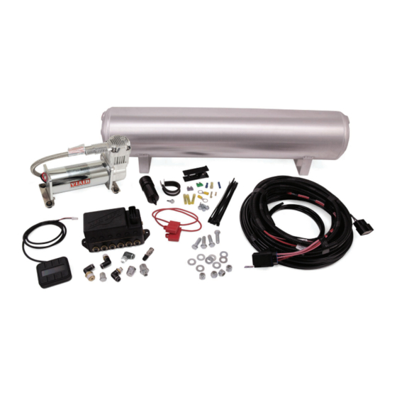
- Page 2 Air Lift Performance Kit Details 27672 HARDWARE LIST Part # Description 72604 4pt Fast Air Manifold - 3/8” ........1 27042 Gen 3 Display ............1 26498-002 Electrical Harness - FastAir .........1 20937 Polyurethane Filter Drain Hose ......5ft 20947 DOT 3/8” Air Line ..........60ft 11517 Miniature Filter .............1...
-
Page 3: Notation Explanation
It is important to read and understand the entire installation guide before beginning installation or performing any maintenance, service or repair. The information includes step-by-step installation information, installation templates and a troubleshooting guide. Air Lift Company reserves the right to make changes and improvements to its products and publications at any time. NOTATION EXPLANATION Hazard notations appear in various locations in this publication. -
Page 4: Installing The Autopilot V2 Kit
If the harness must be lengthened, use properly sized butt connectors and wire. If extending NOTE the power/ground wires, use 8AWG wire minimum or contact Air Lift for more information. The supplied harness is only capable of powering a single compressor. If installing dual compressors, a second dedicated power wire is required. -
Page 5: Install Harness
Air compressors intake moisture (humidity) from the outside air source and will deposit NOTE water in the air tank. The AutoPilot V2 system includes a filter that will greatly reduce the potential for moisture to enter the manifold, however, tanks must be regularly purged to eliminate the possibility of water entering the manifold. -
Page 6: Install Air Lines
Route the 18AWG pink wire to a key switched IGNITION source that remains on during cranking. Examples include: ECU, fuel pump. Do not select an accessory source. If the AutoPilot V2 display shuts off while starting the NOTE vehicle, this is not a true ignition source. -
Page 7: Helpful Tips: Air Line And Fittings
8 different combinations of the 4 corner air spring pressures. After installing AutoPilot V2 in your vehicle, please follow the steps below to properly setup your new system. If changes are made after installing and calibrating the system such as changes to air springs, lines, tank, compressor, or other vehicle modifications, the system must be recalibrated to maintain accuracy. -
Page 8: System Calibration And Settings
Press button 2 to enter CALIBRATE (fig. 3). Press button 1 SYSTEM CAL (fig. 5), follow CALIBRATION MENU instructions to calibrate AutoPilot V2 system to your vehicle. Once calibration is complete, 1. SYSTEM CAL Press buttons (1+5) simultaneously to exit to 2. - Page 9 6. COMP TIME the compressor and measure its inflate time 7. RISE ON START to achieve MAX pressure (fig. 9). AutoPilot V2 8. PSI/BAR & SWV will record this fill time, allowing the operator to compare future fill times to determine fig.
-
Page 10: Program Presets
“Rear up”: for added load of PRESET 1 passengers, equipment. • “Play”: for those that want to enjoy their air suspension freedom, AutoPilot V2 fig. 13 has a special function that recognizes side-to-side presets. When left side EDIT pressures are equal, and right side pressures are equal but >25PSI... - Page 11 Connect direct to battery Connect direct to battery Preferred Preferred Butt connector 30 AMP fuse NOTE: If not run to battery, voltage drop 30 AMP fuse Butt connector may reduce system performance and AL005 NOTE: If not run to battery, voltage drop durability.
- Page 12 **This option must be used for tank P/N10995 This is a moisture drain and must drain to the outside of the vehicle. AIR LINE CUTTING NOTE: Air Lift recommends RIGHT RIGHT using a hose cutting tool RIGHT RIGHT to ensure a proper cut (Air Lift part number 10530).
-
Page 13: Operating The System
Air Lift Performance Operating the System Now that your system is set up, it’s time to use it. If changes are made after installing and calibrating the system such as changes to air springs, lines, tank, or compressor, the system must be recalibrated to maintain system accuracy. -
Page 14: Troubleshooting Guide
Air Lift Performance MANUAL Mode 1. MANUAL mode allows the user to fill or exhaust each spring independently. The display will show arrows above and below the pressures to indicate manual control mode (fig. 17). The arrow will be solid when the spring is filling/exhausting, and outlined when not active. - Page 15 AUTOPILOT V2 GEN 3 PRESSURE CONTROL AUTOPILOT V2 SECOND COMPRESSOR HARNESS*...
-
Page 16: Autopilot V2 Remote Control Unit Dimensions
Air Lift Performance AutoPilot V2 Remote Control Unit Dimensions 2.875” Top View .75” Side View MN-754... -
Page 17: Manifold Template
Air Lift Performance Manifold Template 6.35” MN-754... - Page 18 Air Lift Performance 16380 Compressor Template HOLE PATTERN FOR BOTTOM OF 16380 COMPRESSOR 6.6900 3.3100 MN-754...
-
Page 19: Warranty And Returns Policy
(labor charges) the defective product from the vehicle and returning it, transportation costs prepaid, to the dealer from which it was purchased or to Air Lift Company for verification. Product failures resulting from abnormal use or misuse are excluded from this warranty. The loss of use of the product, loss of time, inconvenience, commercial loss or consequential damages is not covered.
Need help?
Do you have a question about the AutoPilot V2 and is the answer not in the manual?
Questions and answers