Air Lift AutoPilot V2 Installation Manual
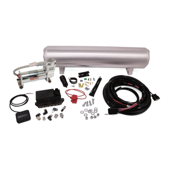
Compressor kit
Hide thumbs
Also See for AutoPilot V2:
- Installation manual (21 pages) ,
- Installation manual (29 pages) ,
- Installation manual (20 pages)
Table of Contents
Advertisement
Advertisement
Chapters
Table of Contents
Troubleshooting

Subscribe to Our Youtube Channel
Related Manuals for Air Lift AutoPilot V2


Summary of Contents for Air Lift AutoPilot V2
- Page 1 Air Lift ™ AutoPilot V2 ™ P A T E N T P E N D I N G PERFORMANCE INSTALLATION GUIDE For maximum effectiveness and safety, please read these instructions completely before proceeding with installation. Failure to read these instructions can result in an...
-
Page 3: Table Of Contents
Installing the AutoPilot V2 Kit . . . . . . . . . . . . . . . . . . -
Page 4: Introduction
The information includes step-by-step installation information, installation templates and a troubleshooting guide. Air Lift Company reserves the right to make changes and improvements to its products and publications at any time. For the latest version of this manual, contact Air Lift Performance at (800) 248-0892 or visit our website at www.airliftperformance.com. -
Page 5: Installing The Autopilot V2 Kit
If the harness must be lengthened, use properly sized butt connectors and wire. If extending NOTE the power/ground wires, use 8AWG wire minimum or contact Air Lift for more information. The supplied harness is only capable of powering a single compressor. If installing dual compressors, a second dedicated power wire is required. -
Page 6: Install Harness
3. Cut an appropriate length of hose from the manifold port T, to the PTC fitting on the tank. 4. Route the drain/fill air line with a schrader valve (preferably outside the vehicle). When cutting plastic air line, only use a standard hose cutter like (Air Lift part number 10530) NOTE or razorblade. -
Page 7: Install Air Lines
Route the 18AWG pink wire to a key switched IGNITION source that remains on during cranking. Examples include: ECU, fuel pump. Do not select an accessory source. If the AutoPilot V2 display shuts off while starting the NOTE vehicle, this is not a true ignition source. -
Page 8: Helpful Tips: Air Line And Fittings
8 different combinations of the 4 corner air spring pressures. After installing AutoPilot V2 in your vehicle, please follow the steps below to properly setup your new system. If changes are made after installing and calibrating the system such as changes to air springs, lines, tank, compressor, or other vehicle modifications, the system must be recalibrated to maintain accuracy. -
Page 9: System Calibration And Settings
Press button 2 to enter CALIBRATE (fig. 3). Press button 1 SYSTEM CAL (fig. 5), follow CALIBRATION MENU instructions to calibrate AutoPilot V2 system to your vehicle. Once calibration is complete, 1. SYSTEM CAL Press buttons (1+5) simultaneously to exit to 2. - Page 10 6. COMP TIME the compressor and measure its inflate time 7. RISE ON START to achieve MAX pressure (fig. 9). AutoPilot V2 8. PSI/BAR & SWV will record this fill time, allowing the operator to compare future fill times to determine fig.
-
Page 11: Program Presets
“Rear up”: for added load of passengers, equipment. PRESET 1 • “Play”: for those that want to enjoy their air suspension freedom, AutoPilot V2 has a special function that recognizes fig. 13 side-to-side presets. When left side pressures are equal, and right side EDIT pressures are equal but >25PSI... - Page 12 Air Lift Performance fig. 15 MN-754...
- Page 13 Air Lift Performance MN-754...
-
Page 14: Operating The System
Air Lift Performance Operating the System Now that your system is set up, it’s time to use it. If changes are made after installing and calibrating the system such as changes to air springs, lines, tank, or compressor, the system must be recalibrated to maintain system accuracy. -
Page 15: Troubleshooting Guide
Air Lift Performance MANUAL Mode 1. MANUAL mode allows the user to fill or exhaust each spring independently. The display will show arrows above and below the pressures to indicate manual control mode (fig. 17). The arrow will be solid when the spring is filling/exhausting, and outlined when not active. -
Page 16: Electrical Schematic
Air Lift Performance Electrical Schematic * Sold seperately Air Lift Part Number 27679 fig. 18 MN-754... -
Page 17: Autopilot V2 Remote Control Unit Dimensions
Air Lift Performance AutoPilot V2 Remote Control Unit Dimensions 2.875” Top View .75” Side View MN-754... - Page 18 Air Lift Performance Notes MN-754...
-
Page 19: Manifold Template
Air Lift Performance Manifold Template 6.35” MN-754... - Page 20 Air Lift Performance Notes MN-754...
-
Page 21: 16380 Compressor Template
Air Lift Performance 16380 Compressor Template HOLE PATTERN FOR BOTTOM OF 16380 COMPRESSOR 6.6900 3.3100 MN-754... - Page 22 Air Lift Performance Notes MN-754...
-
Page 23: Warranty And Returns Policy
Air Lift will repair or replace, at its option, defective products or components. A minimum $10.00 shipping and handling charge will apply to all warranty claims. Before returning any defective product, you must call Air Lift at (800) 248- 0892 in the U.S. and Canada (elsewhere, (517) 322-2144) for a Returned Materials Authorization (RMA) number. - Page 24 Thank you for purchasing Air Lift Performance products! Air Lift Company • 2727 Snow Road • Lansing, MI 48917 or PO Box 80167 • Lansing, MI 48908-0167 Toll Free (800) 248-0892 • Local (517) 322-2144 • Fax (517) 322-0240 • www.airliftperformance.com...
- Page 25 Air Lift Kit 78519 ™ Ford Mustang SN95 PERFORMANCE Front Application CAUTION SEE PAGE 12 BEFORE BEGINNNING INSTALLATION INSTALLATION GUIDE For maximum effectiveness and safety, please read these instructions completely before proceeding with installation. Failure to read these instructions can result in an...
- Page 26 Air Lift Performance MN-933...
- Page 27 Air Lift Performance TABLE OF CONTENTS Introduction . . . . . . . . . . . . . . . . . . . . . . . . . . . . . . . . . . . . . . . . . . . 2 Notation Explanation .
-
Page 28: Introduction
Air Lift Performance reserves the right to make changes and improvements to its products and publications at any time. For the latest version of this manual, contact Air Lift Performance at (800) 248-0892 or visit our website at www.airliftperformance.com. -
Page 29: Installation Diagram
21810 Union, 1/4”FNPT X 1/4” PTC, DOT ... 2 21987 Union, 1/4”FNPT X 3/8” PTC, DOT .... 2 Spanner Wrench ......... 1 Missing or damaged parts? Call Air Lift customer STOP! service at (800) 248-0892 for a replacement part. MN-933... -
Page 30: Installing The Air Suspension
Air Lift Performance Installing the Air Suspension PREPARING THE VEHICLE 1. Elevate and support the vehicle from approved lifting points. 2. Remove the front wheels (fig. 2). fig. 2 REMOVING THE STOCK SUSPENSION 1. Unthread the stabilizer bar end link nuts from the bar (figs. 3 and 4). - Page 31 Air Lift Performance 3. Remove the sensor wire and bracket from the lower strut mount (figs. 7-9). fig. 7 fig. 8 fig. 9 4. Unclip the sensor wire from the two attaching points within the fender housing and move the wire aside (figs.10 and 11).
-
Page 32: Air Suspension Installation
Air Lift Performance Remove the three upper bracket nuts and remove the strut (fig. 13). fig. 13 7. Remove the rivets holding the upper mount support bracket. Make certain the entire rivet has been removed (figs. 14 and 15). fig. 14 fig. - Page 33 Air Lift Performance 2. Attach the upper mount to the slotted strut tower (fig. 17), positioned completely inboard at limit of slots towards the engine. Re-install upper support bracket. Torque nuts to 34 Nm (25 ft-lbs). (Support bracket is not shown in figure 17 to show mount position in slots.)
- Page 34 Air Lift Performance 5. Reinstall the brake rotor and brake caliper (fig. 23). Torque the brake caliper bolts to 88 Nm (65 ft-lbs.). fig. 23 6. Reattach the stabilizer end link (figs. 24 and 25). Torque the nut to 16 Nm (11 ft-lbs.).
-
Page 35: Damping Adjustment
Air Lift Performance 9. Cycle the suspension to Max Extension and record the measurement from the same reference points. 10. Add ME and MC then divide by 2. Set the suspension to this point. This position will give 50% stroke in either direction and is a starting point for ride height (fig. 26). -
Page 36: Adjusting Extended Or Drop Height Using Lower Mount
Air Lift Performance ADJUSTING EXTENDED OR DROP HEIGHT USING LOWER MOUNT Your struts have been pre-set at the factory to provide maximum drop height while maintaining adequate tire clearance to the air spring. If you wish to gain more extended height (lift),... - Page 37 Air Lift Performance WHEN ADJUSTING HEIGHT UPWARDS, MAKE SURE THAT THE STRUT BODY CAUTION ENGAGES ALL THE THREADS OF THE LOWER MOUNT (FIG. 30). WHEN ADJUSTING DOWNWARDS, MAKE SURE THERE IS ADEQUATE AIR SPRING CLEARANCE TO THE TIRE/WHEEL ASSEMBLY. CLEARANCE MUST BE CHECKED WITH SYSTEM FULLY DEFLATED AS WELL AS FULLY INFLATED TO ENSURE THAT NO RUBBING OCCURS.
- Page 38 Air Lift Performance AFTER INITIAL INSTALLATION OF YOUR STRUTS/SHOCKS: CAUTION • DO NOT CYCLE THE SUSPENSION WITH THE AIR-LINE CONNECTED TO THE LEADER HOSE WITHOUT FIRST ADDING AIR SPRING PRESSURE. DOING SO MAY CAUSE THE AIR SPRING TO IMPROPERLY INFLATE (FIG. 31). IT IS SAFE TO CYCLE THE SUSPENSION TO CHECK FOR CLEARANCES ETC.
-
Page 39: Before Operating
Clear lines if necessary. 2. Inflate the air springs to 75-90 PSI and check all connections for leaks. 3. Air Lift part #27669 or #27671, AutoPilot V2 Air Management System, is highly recommended for this product. -
Page 40: Product Use, Maintenance And Servicing
4. Look for a kink or fold in the air line. Reroute as needed. If the preceding steps do not solve the problem, it is possibly caused by a failed air spring — either a factory defect or an operating problem. Please call Air Lift at (800) 248-0892 for assistance. Frequently Asked Questions Q . -
Page 41: Tuning The Air Pressure
2 . Ride comfort If the vehicle has a rough or harsh ride it may be due to either too much pressure or not enough. Try different pressures to determine the best ride comfort. See Air Lift suggested driving air pressure. -
Page 42: Replacement Information
Air Lift will repair or replace, at its option, defective products or components. A minimum $10.00 shipping and handling charge will apply to all warranty claims. Before returning any defective product, you must call Air Lift at (800) 248- 0892 in the U.S. and Canada (elsewhere, (517) 322-2144) for a Returned Materials Authorization (RMA) number. - Page 43 Air Lift Performance Notes MN-933...
- Page 44 Thank you for purchasing Air Lift Performance products! Air Lift Performance • 2727 Snow Road • Lansing, MI 48917 or PO Box 80167 • Lansing, MI 48908-0167 Toll Free (800) 248-0892 • Local (517) 322-2144 • Fax (517) 322-0240 • www.airliftperformance.com...
- Page 45 Air Lift Kit 78619 ™ Ford Mustang SN95 PERFORMANCE Rear Application INSTALLATION GUIDE For maximum effectiveness and safety, please read these instructions completely before proceeding with installation. Failure to read these instructions can result in an incorrect installation.
- Page 46 Air Lift Performance MN-934...
- Page 47 Air Lift Performance TABLE OF CONTENTS Introduction . . . . . . . . . . . . . . . . . . . . . . . . . . . . . . . . . . . . . . . . . . . 2 Notation Explanation .
-
Page 48: Introduction
Air Lift Performance reserves the right to make changes and improvements to its products and publications at any time. For the latest version of this manual, contact Air Lift Performance at (800) 248-0892 or visit our website at www.airliftperformance.com. -
Page 49: Installation Diagram
Spacer, Centering, SN95 ......2 17101 3/8-16 X 3/4” Hex Bolt ........ 2 26768 Shock, SN95 Rear ........2 Spanner Wrench ......... 1 Missing or damaged parts? Call Air Lift customer STOP! service at (800) 248-0892 for a replacement part. MN-934... -
Page 50: Installing The Air Suspension
Air Lift Performance Installing the Air Suspension PREPARING THE VEHICLE 1. Elevate and support the vehicle from approved lifting points. 2. Remove the rear wheels (fig. 2). fig. 2 REMOVING THE STOCK SUSPENSION 1. Unbolt the stabilizer bar from the lower control arms (figs. 3 and 4). - Page 51 Air Lift Performance 3. Reattach the lower control arm to the axle. Do not torque the bolt at this time (fig. 7). fig. 7 4. Reinstall the stabilizer bar (figs. 8 and 9). Torque bolts to 47 Nm (35 ft-lbs.).
-
Page 52: Air Suspension Installation
Air Lift Performance 6. Within the trunk, remove the carpet, unthread the rod nut and remove the shock from the vehicle (figs. 12 and 13). fig. 12 fig. 13 AIR SUSPENSION INSTALLATION 1. Install the leader hose into the air spring. Apply thread sealant to the threads of the leader hose. - Page 53 Air Lift Performance 3. Route the leader hose through the hole in the center of the upper spring perch and out the windowed area facing the rear of the vehicle (fig. 16). fig. 16 Braided hose is not shown but routes in the same manner.
- Page 54 Air Lift Performance 6. Remove the shock rod nut, upper washer and bushing from the new shock. Insert the shock into the shock tower, aligning the lower mount hole with the shock mounting bracket and insert the lower shock bolt through the mount (figs. 21-23). Do not torque at this time.
-
Page 55: Damping Adjustment
Air Lift Performance 12. With the suspension at this position, loosen, then re-torque the upper and lower control arm bolts and lower shock bolts to manufacturer’s specifications (Table 1). Re-clocking the control arm bushings is critical to good ride quality, handling and bushing NOTE life. -
Page 56: Adjusting Extended Or Drop Height Using Lower Mount
Air Lift Performance ADJUSTING EXTENDED OR DROP HEIGHT USING LOWER MOUNT Your dampers have been pre-set at the factory to provide maximum drop height while maintaining adequate tire clearance to the air spring. If you wish to gain more extended... - Page 57 Air Lift Performance WHEN ADJUSTING HEIGHT UPWARDS, MAKE SURE THAT THE DAMPER BODY CAUTION ENGAGES ALL THE THREADS OF THE LOWER MOUNT (FIG. 31). WHEN ADJUSTING DOWNWARDS, MAKE SURE THERE IS ADEQUATE AIR SPRING CLEARANCE TO THE TIRE/WHEEL ASSEMBLY. CLEARANCE MUST BE CHECKED WITH SYSTEM FULLY DEFLATED AS WELL AS FULLY INFLATED TO ENSURE THAT NO RUBBING OCCURS.
-
Page 58: Before Operating
Clear lines if necessary. 2. Inflate the air springs to 75-90 PSI and check all connections for leaks. 3. Air Lift part #27669 or #27671, AutoPilot V2 Air Management System, is highly recommended for this product. -
Page 59: Product Use, Maintenance And Servicing
4. Look for a kink or fold in the air line. Reroute as needed. If the preceding steps do not solve the problem, it is possibly caused by a failed air spring — either a factory defect or an operating problem. Please call Air Lift at (800) 248-0892 for assistance. Frequently Asked Questions Q . -
Page 60: Tuning The Air Pressure
2 . Ride comfort If the vehicle has a rough or harsh ride it may be due to either too much pressure or not enough. Try different pressures to determine the best ride comfort. See Air Lift suggested driving air pressure. -
Page 61: Replacement Information
Air Lift will repair or replace, at its option, defective products or components. A minimum $10.00 shipping and handling charge will apply to all warranty claims. Before returning any defective product, you must call Air Lift at (800) 248- 0892 in the U.S. and Canada (elsewhere, (517) 322-2144) for a Returned Materials Authorization (RMA) number. - Page 62 Air Lift Performance Notes MN-934...
- Page 63 Air Lift Performance Notes MN-934...
- Page 64 Thank you for purchasing Air Lift Performance products! Air Lift Performance • 2727 Snow Road • Lansing, MI 48917 or PO Box 80167 • Lansing, MI 48908-0167 Toll Free (800) 248-0892 • Local (517) 322-2144 • Fax (517) 322-0240 • www.airliftperformance.com...
Need help?
Do you have a question about the AutoPilot V2 and is the answer not in the manual?
Questions and answers