Air Lift AutoPilot V2 Installation Manual
Digital air management
Hide thumbs
Also See for AutoPilot V2:
- Installation manual (64 pages) ,
- Installation manual (21 pages) ,
- Installation manual (20 pages)
Table of Contents
Advertisement
Quick Links
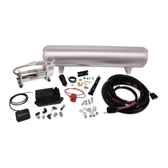
Kit Details
27669
HARDWARE LIST
Part #
Description
72604
4pt Fast Air Manifold - 3/8".................. 1
27042
Gen 3 Display ..................................... 1
26498-002
Electrical Harness - FastAir ................ 1
20937
Polyurethane Filter Drain Hose ......... 5ft
20947
DOT 3/8" Air Line ............................60ft
24672
Fuse, spade 3amp ............................. 1
24547
Fuse, spade, 30amp ........................... 1
24500
ATC Fuse holder w/ cap ..................... 2
24645
16GA Butt Connector .......................... 1
24752
12-10GA Butt Connector..................... 3
24748
12GA Ring Terminal 3/8" .................... 2
24524
Female Spade Terminal...................... 1
24595
12GA Female Spade Terminal .......... 1
24561
Adaptor, Mini Fuse .............................. 1
24542
ATC/ATO Fuse Adaptor ...................... 1
21043
1/4" MNPT X 1/4" PTC Elbow ............. 1
21633
Push Lock Valve .................................1
MN-783 • (041606) • ECR 8450
Qty
Missing or damaged parts? Call Air Lift customer
STOP!
service at (800) 248-0892 for a replacement part.
Part #
Description
20946
DOT 1/4" Air Line .............................. 2ft
21585
1/4" Pipe Plug ..................................... 1
21737
3/8" Pipe Plug ..................................... 1
21773
3/8" MNPT X 1/8" MNPT Adapter ....... 1
21854
1/8" MNPT X 3/8" PTC Elbow ............. 2
21855
3/8" MNPT X 3/8" PTC Elbow ............. 1
18444
3/8" Flat Washer ................................. 8
17188
3/8-16 x 1.25 Hex Cap Screw ............. 4
17263
1/4-14 x 1 Self Tapping Screw ............ 3
18435
3/8-16 Nylon Lock Nut ........................ 4
11517
Miniature Filter ....................................1
11217
P Clamp ..............................................1
17173
1/4"-14 X 3/4" Self Tapping Screw ...... 1
16444
VIAIR 444C Compressor (200 psi) ..... 1
11955
4 Gallon Aluminum Air Tank ............... 1
10466
8" Zip Tie ...........................................10
10530
Air Line Cutter ..................................... 1
Air Lift Performance
Qty
Advertisement
Table of Contents

Related Manuals for Air Lift AutoPilot V2


Summary of Contents for Air Lift AutoPilot V2
- Page 1 1/4” MNPT X 1/4” PTC Elbow ..... 1 10530 Air Line Cutter ........1 21633 Push Lock Valve .........1 Missing or damaged parts? Call Air Lift customer STOP! service at (800) 248-0892 for a replacement part. MN-783 • (041606) • ECR 8450...
- Page 2 AutoPilot V2 ™ P A T E N T P E N D I N G INSTALLATION GUIDE For maximum effectiveness and safety, please read these instructions completely before proceeding with installation. Failure to read these instructions can result in an...
-
Page 4: Table Of Contents
Installing the AutoPilot V2 Kit . . . . . . . . . . . . . . . . . . -
Page 5: Introduction
The information includes step-by-step installation information, installation templates and a troubleshooting guide. Air Lift Company reserves the right to make changes and improvements to its products and publications at any time. For the latest version of this manual, contact Air Lift Performance at (800) 248-0892 or visit our website at www .airliftperformance .com. -
Page 6: Installing The Autopilot V2 Kit
If the harness must be lengthened, use properly sized butt connectors and wire. If extending NOTE the power/ground wires, use 8AWG wire minimum or contact Air Lift for more information. The supplied harness is only capable of powering a single compressor. If installing dual compressors, a second dedicated power wire is required. -
Page 7: Install Harness
Air compressors intake moisture (humidity) from the outside air and will deposit water in the air NOTE tank. The AutoPilot V2 system includes a filter that will greatly reduce the potential for moisture to enter the manifold, however, tanks must be regularly purged to eliminate the possibility of water entering the manifold. -
Page 8: Install Air Lines
Route the 18AWG pink wire to a key switched IGNITION source that remains on during cranking. Examples include: ECU, fuel pump. Do not select an accessory source. If the AutoPilot V2 display shuts off while starting the NOTE vehicle, this is not a true ignition source. -
Page 9: Helpful Tips: Air Line And Fittings
8 different combinations of the 4 corner air spring pressures. After installing AutoPilot V2 in your vehicle, please follow the steps below to properly set up your new system. If changes are made after installing and calibrating the system such as changes to air springs, lines, tank, compressor, or other vehicle modifications, the system must be recalibrated to maintain accuracy. -
Page 10: System Calibration And Settings
Press button 2 to enter CALIBRATE (fig. 3). Press button 1 SYSTEM CAL (fig. 5), follow CALIBRATION MENU instructions to calibrate AutoPilot V2 system to your vehicle. Once calibration is complete, 1. SYSTEM CAL Press buttons (1+5) simultaneously to exit to 2. - Page 11 6. COMP TIME the compressor and measure its inflate time 7. RISE ON START to achieve MAX pressure (fig. 9). AutoPilot V2 8. PSI/BAR & SWV will record this fill time, allowing the operator to compare future fill times to determine fig.
-
Page 12: Program Presets
“Rear up”: for added load of PRESET 1 passengers, equipment. • “Play”: for those that want to enjoy their air suspension freedom, AutoPilot V2 fig. 13 has a special function that recognizes side-to-side presets. When left side EDIT pressures are equal, and right side pressures are equal but >25PSI... - Page 13 Air Lift Performance fig. 15 MN-754...
- Page 14 Air Lift Performance MN-754...
-
Page 15: Operating The System
Air Lift Performance Operating the System Now that your system is set up, it’s time to use it. If changes are made after installing and calibrating the system such as changes to air springs, lines, tank, or compressor, the system must be recalibrated to maintain system accuracy. -
Page 16: Troubleshooting Guide
Air Lift Performance MANUAL Mode 1. MANUAL mode allows the user to fill or exhaust each spring independently. The display will show arrows above and below the pressures to indicate manual control mode (fig. 17). The arrow will be solid when the spring is filling/exhausting, and outlined when not active. -
Page 17: Electrical Schematic
Air Lift Performance Electrical Schematic * Sold separately Air Lift Part Number 27679 fig. 18 MN-754... -
Page 18: Autopilot V2 Remote Control Unit Dimensions
Air Lift Performance AutoPilot V2 Remote Control Unit Dimensions 2.875” Top View .75” Side View MN-754... - Page 19 Air Lift Performance Notes MN-754...
-
Page 20: Manifold Template
Air Lift Performance Manifold Template IMPORTANT: PRINT THIS MANUAL AT 100% SCALE. THIS MANUAL CONTAINS A CAUTION DRILLING TEMPLATE, WHICH WOULD BE RENDERED INCORRECT IN DIMENSION IF PRINTED WITH ANY SCALING. USING AN INCORRECT TEMPLATE TO DRILL HOLES MAY CAUSE DAMAGE TO THE VEHICLE! PLEASE REFER TO THE ONE-INCH SCALE (FIG. - Page 21 Air Lift Performance...
-
Page 22: 16444 Compressor Mounting Template
Air Lift Performance HOLE PATTERN FOR 16444 COMPRESSOR 8 1/2” 3 5/16” MN-754... - Page 23 Air Lift Performance...
- Page 24 Air Lift Performance Notes MN-754...
- Page 25 Air Lift Performance Notes MN-754...
- Page 26 Air Lift Performance Notes MN-754...
-
Page 27: Limited Warranty And Return Policy
Air Lift Company, for all Air Lift Performance products, except its Air Lift Performance 3H™ and 3P™ systems, warrants to the original purchaser for a period of one year from the date of original purchase that the Air Lift Performance damper kits will be free from defects in workmanship and materials for the normal expected life of the part when used on cars and trucks as specified by Air Lift Company and under normal operating conditions, subject to the requirements and exclusions set forth below. -
Page 28: Replacement Information
Air Lift Performance Replacement Part Information If replacement parts are needed, contact the local dealer or call Air Lift customer service at (800) 248-0892. Most parts are immediately available and can be shipped the same day. Contact Air Lift Company customer service at (800) 248-0892 first if: •... - Page 29 Thank you for purchasing Air Lift Performance products! Air Lift Company • 2727 Snow Road • Lansing, MI 48917 or PO Box 80167 • Lansing, MI 48908-0167 Toll Free (800) 248-0892 • Local (517) 322-2144 • Fax (517) 322-0240 • www.airliftperformance.com...
Need help?
Do you have a question about the AutoPilot V2 and is the answer not in the manual?
Questions and answers