Table of Contents
Advertisement
Advertisement
Table of Contents

Related Manuals for Air Lift LoadLifter 7500 XL


Summary of Contents for Air Lift LoadLifter 7500 XL
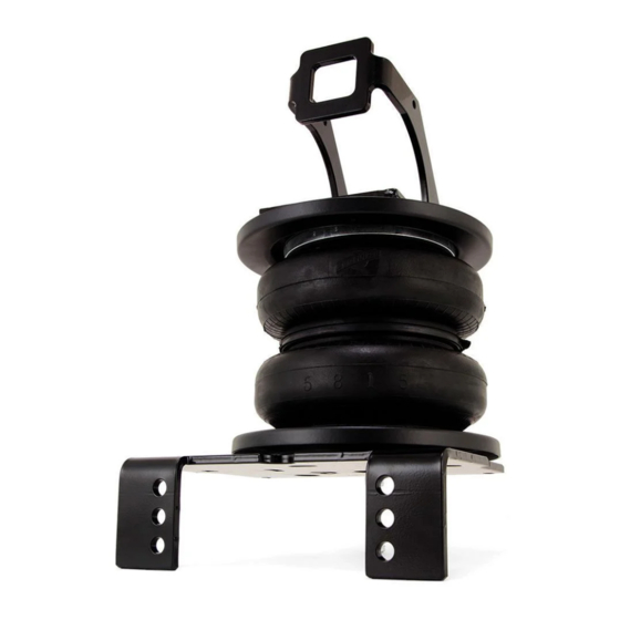
- Page 1 Installation Guide Kit 57596 Ford Super Duty Representative vehicle image For maximum effectiveness and safety, please read these instructions completely before proceeding with installation. MN-1033 • (032004) • ECR 9273 Failure to read these instructions can result in an incorrect installation.
-
Page 3: Table Of Contents
Notation Explanation . . . . . . . . . . . . . . . . . . . . . . . . . . . . . . . . . . . . . . . . . . . . . . . . . . . 4 D. Installing the LoadLifter 7500 XL System ....5 Getting Started . -
Page 4: Installation Diagrams
LoadLifter 7500 XL A. Installation Diagrams EE OR GG EE OR GG Passenger’s (right) side Driver’s (left) side N OR CC Q OR CC N OR CC Q OR CC * NOTE: If the vehicle has a fifth-wheel hitch installed that has side plates along the frame, use the existing hardware that was removed. -
Page 5: Hardware And Tools Lists
Air compressor or compressed air source ....1 Spray bottle with dish soap/water solution ....1 Missing or damaged parts? Call Air Lift customer STOP! STOP! service at (800) 248-0892 for a replacement part . -
Page 6: Introduction
. Air Lift Company reserves the right to make changes and improvements to its products and publications at any time . For the latest version of this manual, contact Air Lift Company at (800) 248-0892 or visit airliftcompany.com . -
Page 7: Installing The Loadlifter 7500 Xl System
LoadLifter 7500 XL D. Installing the LoadLifter 7500 XL System GETTING STARTED 1 . Raise the vehicle and support it in a way, using safety stands or equivalent, that the axle can be safely lowered away from the frame . This will need to be done in order for the air spring assembly to be put into position between the axle and frame (Fig . -
Page 8: Installing The Braces
LoadLifter 7500 XL 3 . If necessary, disconnect the wiring harness from the driver’s (left) side frame rail to gain clearance for the upper brace (Fig . D .4) . Also, push out the harness connector that holds the electrical lines going to the gas/DEF tank in or out of the tank bracket . This will improve socket/bolt access required for installing and tightening the frame brace (Fig . -
Page 9: Retaining Clip L-Bracket Installation On Brace
LoadLifter 7500 XL Image shows lines clear on the frame, opening it up for the brace installation . fig. D.7 RETAINING CLIP L-BRACKET INSTALLATION ON BRACE 1 . In order to reattach the previously removed emissions line, attach the provided L-bracket (K) to the back frame brace using the 1/4"-20 x 1"... -
Page 10: Driver's (Left) Side Brace Installation
LoadLifter 7500 XL DRIVER’S (LEFT) SIDE BRACE INSTALLATION 1 . Set the left upper brace (E) into the driver’s side frame rail . The brace has a small hole that will line up with an existing hole in the frame . Insert the M8-1 .25 x 25mm hex- cap screw (P) with an M8 flat washer (X) through the brace and frame (Figs . - Page 11 LoadLifter 7500 XL If the truck has an aftermarket fifth-wheel hitch that has an outer bracket (plate) running along side of the frame and it used this slot to secure the bracket with existing hardware, install the original fifth-wheel hardware previously removed in the Getting Started section from the fifth-wheel installation for securing the brace (Fig .
-
Page 12: Passenger's (Right) Side Brace Installation
LoadLifter 7500 XL PASSENGER'S (RIGHT) SIDE BRACE INSTALLATION 1 . Set the right upper brace (C) into the passenger's (right) side frame rail (Figs . D .15, D .16 & D .17) . Inside view of passenger’s (right) side frame shown fig. -
Page 13: Air Spring And Bracket Assembly
LoadLifter 7500 XL 2 . For trucks with no fifth-wheel or the OEM purchased Reese fifth-wheel hitch, insert the 1/2"-13 x 1 1/2" hex-cap screw (N) and 1/2" thick flat washer (EE) through the brace, between the brace and the frame add the 1/2" thick flat washer (EE) then through the frame (from the inside out) . - Page 14 LoadLifter 7500 XL 3 . Insert a 5/16"-18 x 1" carriage bolt (BB) through the square hole in the lower bracket cup (B) . Make sure to insert the carriage bolt on the flanged side of the bracket . Set the assembly onto the lower bracket main plate (A) making sure the lower bracket cup (B) is on the flanged side of the bracket (Fig .
- Page 15 LoadLifter 7500 XL NOTE The 3/8"-16 x 10" carriage bolts will be behind the axle once the assembly is installed on the axle. 6 . The lower bracket assembly has two sets of air spring mounting holes, one for the driver’s (left) side, the other for the passenger’s (right) side .
- Page 16 LoadLifter 7500 XL TECH TIP Cut a small section of cardboard and fold it in half. When assembling the upper bracket to the air spring, set this cutout under the carriage bolt between the roll plate and upper bracket to hold the carriage bolt in place. This will make it easier to tighten the mounting hardware once in place on the frame (Fig.
- Page 17 LoadLifter 7500 XL 9 . Set the driver’s (left) side upper bracket onto the driver’s (left) side air spring assembly previously assembled, using the holes in the upper bracket designated (Fig . D .29), and attach to the air spring with two 3/8" flat washers (V), 3/8" lock washers (SS) and 3/8"-24 x 7/8"...
-
Page 18: Attaching The Assemblies To The Frame
LoadLifter 7500 XL 12 . Figure D .35 shows the assemblies complete and ready to install . Driver’s Passenger’s (left) side (right) side assembly assembly fig. D.35 ATTACHING THE ASSEMBLIES TO THE FRAME 1 . Drop the axle or raise the frame to make room to put the assemblies into position . - Page 19 LoadLifter 7500 XL 3 . Set the passenger's (right) side assembly into position on the jounce bumper strike plate the same way the left side was positioned (Fig . D .38) . Note: the long carriage bolt goes outside of the hard brake line on the passenger's (right) side .
- Page 20 LoadLifter 7500 XL 6 . Cap the 3/8"-16 x 1 1/4" carriage bolts (O) with 3/8" flat washers (V) and 3/8"-16 nylon lock nuts (U) on both sides and torque to 15 lb .-ft . (20Nm) (Fig . D .41) .
-
Page 21: Attaching The Lower Bracket To The Axle
LoadLifter 7500 XL ATTACHING THE LOWER BRACKET TO THE AXLE 1 . Push the lower bracket up against the stock U-bolts so that the legs of the lower bracket are locked into position around the stock U-bolts (Fig . D .44) . It may be necessary to rotate the lower bracket on the jounce bumper strike plate in order to do this . - Page 22 LoadLifter 7500 XL 4 . Cap U-bolts with two 3/8" flat washers (V), and two 3/8"-16 nylon lock nuts (U) and evenly tighten only enough to draw the bracket up against the stock U-bolt at this time (Fig . D .47) . Repeat for the other side . Make sure the bracket rests against the stock U-bolts (Fig .
- Page 23 LoadLifter 7500 XL 6 . Tighten the axle clamp bar hardware evenly until it touches the axle (see note below) . Torque the axle clamp bar bolts to 16 lb .-ft . (22Nm) (Fig . D .50) . Repeat for the opposite side .
- Page 24 LoadLifter 7500 XL 10 . Remove the two bolts that hold the emergency brake cable wire brackets to the frame on the driver's (left) side and install the two emergency brake cable spacer brackets to the frame using the existing hardware removed earlier . The emergency brake cable secondary bracket (XX) installs the farthest back on the driver's (left) side frame (Fig .
-
Page 25: Installing The Air Lines
Braided Nylon air line stainless LoadLifter 7500 XL to compressor steel air line system and to air spring Schrader valve E. Installing the Air Lines Choose the locations for the Schrader valves and drill a 5/16" (8mm) hole, if necessary (Fig . -
Page 26: Finished Installation Photos
LoadLifter 7500 XL F. Finished Installation Photos 1 . The following images show the finished installation of both sides . (Figs . F .1, F .2, F .3 & F .4) fig. F.1 fig. F.2 Back, driver's (left) side Back center, driver's (left) side rear view of the kit installed . -
Page 27: Before Operating
GROSS VEHICLE WEIGHT RATING . Limited Warranty and Return Policy Air Lift Company provides a limited lifetime warranty to the original purchaser of its load support products, that the products will be free from defects in workmanship and materials when used... - Page 28 Thank you for purchasing Air Lift products — the professional installer’s choice! Air Lift Company • 2727 Snow Road • Lansing, MI 48917 or P.O. Box 80167 • Lansing, MI 48908-0167 Toll Free (800) 248-0892 • Local (517) 322-2144 Fax (517) 322-0240 • www.airliftcompany.com...
Need help?
Do you have a question about the LoadLifter 7500 XL and is the answer not in the manual?
Questions and answers
What does the caution symbol mean on remote