Table of Contents
Advertisement
Quick Links
Thank you for purchasing KOPROPO EX-5FH. Please readand fully understand this instruction manual prior to useR/C models.
EX-5FH Features
Though developed as a well balanced and controllable entry model, the EX-5FH high-response transmitter uses
2.4GHz as a frequency and allows for simultaneous operation without checking for unused frequency bands.
EX-5FH is equipped with D.D.S. high response and is equivalent to a high-end model and widely recommended from
beginners to enthusiasts. 27 functions allows you to make detailed settings for R/C races.
The connection method of the peripheral devices is different for an electric car and engine car. Please refer to the
explanation chart below.
Set components and cable connection
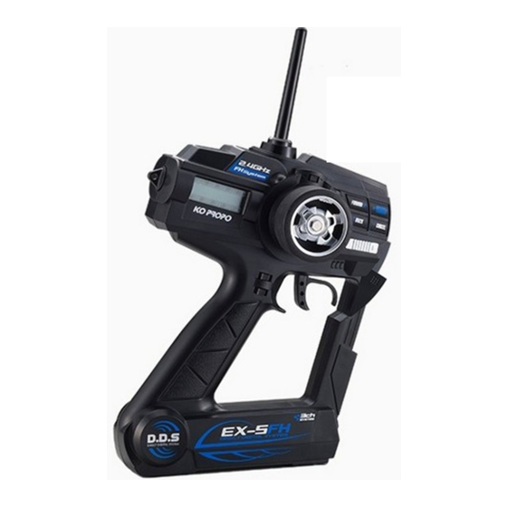
●Transmitter
(EX-5FH)
●Stand spacer
MADE IN JAPAN
● For electric cars
●Running battery (not included)
●Servo
●Receiver
● For gas cars
●Servo
●Compatible Receiver : KR-211FH/KR-211FHG
KR-411FH/KR-413FH (Available Feb 2014)
Instruction manual
(CH1: Steering servo CH2: ESC)
●Receiver
(CH1: Steering servo CH2: Shrottle servo)
●Motor (not included)
●ESC (Speed controller)
●Receiver battery
(not included)
1
Advertisement
Table of Contents

Summary of Contents for Ko Propo EX-5FH
- Page 1 Instruction manual Thank you for purchasing KOPROPO EX-5FH. Please readand fully understand this instruction manual prior to useR/C models. EX-5FH Features Though developed as a well balanced and controllable entry model, the EX-5FH high-response transmitter uses 2.4GHz as a frequency and allows for simultaneous operation without checking for unused frequency bands. EX-5FH is equipped with D.D.S. high response and is equivalent to a high-end model and widely recommended from beginners to enthusiasts. 27 functions allows you to make detailed settings for R/C races. The connection method of the peripheral devices is different for an electric car and engine car. Please refer to the explanation chart below. Set components and cable connection ● For electric cars ●Motor (not included) ●Running battery (not included) ●Transmitter (EX-5FH) ●Servo ●ESC (Speed controller) ●Receiver (CH1: Steering servo CH2: ESC) ● For gas cars ●Receiver battery (not included) ●Receiver ●Servo ●Stand spacer (CH1: Steering servo CH2: Shrottle servo)...
-
Page 2: For Safe Operation
■ For safe operation For safe operation With the nature of radio controlled model, improper usage may result in serious accidents. In order to avoid these circumstances, please read following contents before use. We cannot be held responsible for problems encountered when not complying with these cautions and notices. Warning! Failure to observe the matter discussed in such an item poses a serious threat of death or severe injury. Caution! Failure to observe the matter discussed in such an item poses a possibility of injury or damage to the equipment or property. Caution when installing units ●Make sure metal parts do not come in direct contact to model (chassis/ship hull) by vibration. ※Noise of metal parts may result in malfunction of receiver, and the model may run out of control Warning! ●Do not cut or bundle receiver antenna with other cables. Prohibited matters ※It may result in decreasing the sensitivity of receiver and may result in the model running out of control. ●Note polarity when installing batteries to transmitter and receiver. ※It may damage R/C units. ●Be sure to connect receiver, servo and switch connectors correctly. ※If connections are loosened by vibration, the model may run out of control. ●Attach receiver using thick double-sided tape to avoid direct contact with other parts. ※Strong shock and vibration may result in the model running out of control. Warning! ●Operate servo to check that there are no unnecessary forces onto the push rod. Enforcement matters ※It may damage the servo or increase the consumption of batteries. -
Page 3: Name Of Parts
■ Name of parts/Unit preparation Name of parts ●Transmitter (EX-5FH) LCD display (factory setting) ET1 lever Model name (MENU26) Voltage Antenna (Steering trim) Steering wheel ET2 lever (Throttle trim) LCD indicates voltage after a certain period of time. Foward key ※Alarm sounds when batteries are depleted. Install fresh batteries as soon as possible to keep radio power. +/ Enter key −/ Cancel key Back key ●Receiver ( KR-211FH/212FHG) Power switch ET3 lever Channel 1〜2 (Steering travel) connector Power Battery Throttle trigger ET4 lever connector connector (3ch control) (KR-212 FHG only) Ch1 : Sterring servo CH2 : ESC or Throttle servo Battery box (inside) -
Page 4: Notes On Installing Receiver (Anti-Noise Measures)
■ Notes on installing receiver (anti-noise measures) Notes on installing receiver (anti-noise measures) Locate antenna cable as far away from noise source! Carbon chassis Battery Be careful of noise! Assume that all areas where large currents are flowing are generating noise! Locate antenna cables and receiver as far away from the motor, ESC, silicone cords as possible. (Materials such as metal receiver motor or carbon chassis also conduct noise) R/C model is controlled by radio wave. Therefore, anti-noise measures are the most important factor. Take measures to ensure optimum performance of your R/C model and driving technique. ... - Page 5 ■ Pairing/Steering/Throttle/ABS ▶How to pairing Register receiver to the transmitter 1. Forward key + Back key ① Hold both Forward and Back keys and switch transmitter on. ② "PAIR" (blinking sign) will be displayed on the LCD screen and alarm sounds. ③ Blinking and alarm stops after approx. 5 seconds. Then LCD screen displays PAIR . Now the transmitter is ready. ④ Move receiver close to the transmitter (approx. within 1m) ⑤ Hold set button of the receiver then switch on. ⑥ Release set button. Receiver LED indicator turns on 2. Power switch after pairing is completed. Switch off both transmitter and receiver. 2. Power Check movement ▶ ① Switch on the transmitter first, then switch on the 1. Set button receiver. Confirm that the receiver LED indicator lit up. ② Check movement of the servo and the amplifier. ▶Adjusting steering Adjusting turning angle of the steering servo. ① Adjust MENU02: Steering trim to 0 (default setting) ② Adjust "MENU08: Steering sub-trim" so that the car run straight with the steering in neutral. ③ Operate steering wheel. Make sure that the setting does not lock the linkage. In this case, reduce values in "MENU03: Steering travel". If turning angle is not enough, adjust each left and right angle at the maximum in "MENU04: Steering balance R" and "MENU05 steering balance L". ※If left and right turning radius are not same at low speed running, increase values of steering balance of smaller radius to adjust. Adjust steering travel to reduce turning angle if car turns excessively while high-speed running. ※Frequent setting or worn-out linkage will deteriorate balance of steering. Periodical adjustment is recommended to keep performance of steering. ▶Adjusting throttle Adjust the movement amount of speed controller (electric car) / throttle linkage (gas car) When using with electric car: Refer to the instructions included with ESC.
-
Page 6: Procedure When Running
■ Procedure when running/Functions (1-27) Procedure when running 1. Power on: Note surroundings and switch transmitter on, then switch receiver on. 2. Checking model: Confirm model to be used. 3. Checking movements: Raise wheels from ground and operate transmitter to check movements. Detail adjustment using steering/throttle trim lever should be done while running. Adjust steering balance by operating 8-figure running. Trim lever 8-figure running Stand 4. Power off: Switch off in receiver, transmitter order and remove running battery. ※Make sure to switch the transmitter on and off after an interval of at least 2 seconds. Functions (1-27) ▶Select using FORWARD/BACK button MENU10:Throttle monitor ‥‥‥ ※The transmitter automatically memorizes each setting 1 second after changing. When switching transmitter off, wait MENU11:Throttle trim‥‥‥‥‥ more than 2 seconds after changing settings. MENU12:Throttle high point‥‥ P.10 MENU13:Throttle brake ‥‥‥‥ P.10 MENU01:Steering monitor‥‥‥ MENU14:Throttle speed‥‥‥‥ P.10 MENU02:Steering trim‥‥‥‥‥ MENU15:Throttle curve F ‥‥‥ P.11 MENU03:Steering travel‥‥‥‥ MENU16:Throttle curve B ‥‥‥ P.11 MENU04:Steering balance R‥‥ MENU17:Throttle sub trim‥‥‥ P.11 MENU05:Steering balance L‥‥ MENU18:Throttle reverse ‥‥‥... - Page 7 ■MENU 01〜04 Neutral position MENU01:Steering monitor ▶Displays the current position of steering. If steering direction is changed in reverse position, movement of steering and L/R will be reversed accordingly. MENU02:Steering trim L50 〜 0 (Default setting) 〜 R50 ▶Neutral position of steering can be adjusted while running. ET1 lever Adjust using +/− keys. Push both keys together to reset. + key − key ※Max. width may be changed according to steering travel/balance settings. The position of the end point does not move. Only the neutral position moves. When changing the edge of movement, adjust in "MENU08:Steering sub trim". Steering trim can also be adjusted by using ET1 lever. MENU03:Steering travel 40 〜 100 (Default setting) 〜 120 ▶This function allows you to adjust the amount of servo movement when fully turning steering wheel. + key Adjust using +/− keys. Push both keys together to reset. − key Make sure the setting does not cause excessive force to Caution! the servo as it may result in malfunction. Steering travel can also be adjusted using ET3 lever. When adjusting right and left movement individually, adjust in ET3 lever "MENU04: Steering balance R" and "MENU05: Steering balance L".
- Page 8 ■MENU 05〜07 40 〜 70 (Default setting) 〜 100 MENU05:Steering balance L ▶This function allows you to adjust left turning angle. (Use to correct left and right turning radius) + key Adjust using +/− keys. Push both keys together to reset. − key Fully turn steering wheel to left and operate ET1 lever to make setting of steering balance L. MENU06:Steering speed 100 〜 0 (Default setting) 〜 +30 ▶Use this function to adjust the steering speed when turning steering wheel. + key Adjust using +/− keys. Push both keys together to reset. − key ※It effects on both TURN and RETURN directions. Speed type servo may not move smoothly due to excessive speed if sets over +30 values. Steering speed + may not work effectively due to performance of servo. MENU07:Steering curve 50 〜 0 (Default setting) 〜 +50 ▶Use this function to adjust an initial response of the steering servo. + key Adjust using +/− keys. Push both keys together to reset. − key ※+: Initial reaction is increased and decreased toward the end ...
- Page 9 ■MENU 08〜11 L25 〜 0 (Default setting) 〜 R25 MENU08:Steering sub trim ▶This function allows you to adjust the edge of operation and neutral position at the same time. (Use when installing servo and test running) + key − key Adjust using +/− keys. Push both keys together to reset. Adjust "MENU02: Steering trim" to adjust neutral position only. When value of the sub trim gets bigger, adjust the linkage and make it a smaller the value. In certain circumstances, too big value may cause dead area (servo does not react) at the edge of operation. MENU09:Steering reverse REV (Default setting) / NORM ▶This function allows you to change the direction of servo movement (Use this function when the turning direction of servo is opposite to the transmitter operation) + key − key Adjust using +/− keys. Push both keys together to reset. ※REV:Reverse NORM:Normal Neutral position MENU10:Throttle monitor ▶Displays current throttle position. If throttle direction is in reverse position, throttle movement and F/b indication of monitor will be reversed accordingly. b50 〜 0 (Default setting) 〜 F50 MENU11:Throttle trim ▶Adjust neutral position of throttle while running ET2 lever...
- Page 10 ■MENU 12〜14 0 〜 70 (Default setting) 〜 100 MENU12:Throttle high point ▶Sets only the max forward movement on throttle. (Allows you to adjust highest point of ESC of electric car or high carburetor of gas car) + key − key Adjust using +/− keys. Push both keys together to reset. Caution! Creating a large value for a gas car puts an increase burden on servo and may result in damage. Caution! In an electric car, when set value is too small the ESC can not show a better performance. Please start from +70 (factory setting) setup. Caution! Minimum value is 0 but doesn t operate to forward. Also, throttle servo does not move. Caution! When a small the value of Throttle high point is made, and then a large value in MENU11: Throttle trim is set to an advance direction, the amount of operation will be extremely small. MENU13:Throttle brake 0 〜 70 (Default setting) 〜 100 ▶Adjust only the brake of throttle and max movement of reverse running. + key Adjust using +/− keys. Push both keys together to reset.
- Page 11 ■MENU 15〜17 50 〜 0 (Default setting) 〜 +50 MENU15:Throttle curve F ▶This function allows you to adjust throttle servo move- ment on actual trigger operation (forward only). + key Adjust using +/− keys. Push both keys together to reset. − key ※The throttle response can be made quick (+) or mild (−) + makes quick at start, and mild later − makes mild at start, sensitive later Quick curve (+ values) reacts greatly at the start, and the response becomes mild later Mild curve (− values) reacts mild at the start, and the response becomes sensitive later When using with other function, check the effect one by one. MENU16:Throttle curve B 50 〜 0 (Default setting) 〜 +50 ▶This function allows you to adjust throttle servo move- ment on actual trigger operation (braking only). + key Adjust using +/− keys. Push both keys together to reset. − key ※The throttle response can be made quick (+) or mild (−) + makes quick at start, and mild later − makes mild at start, sensitive later Quick curve (+ values) reacts greatly at the start, and the response becomes mild later Mild curve (− values) reacts mild at the start, and the response becomes sensitive later When using with other function, check the effect one by one. MENU17:Throttle sub trim b30 〜 0 (Default setting)...
- Page 12 ■MENU 18〜20 REV (Default setting) / NORM MENU18:Throttle reverse ▶You can change the direction of throttle movement (Use this function when the turning direction of servo is opposite to the transmitter operation) + key − key Adjust using +/− keys. Push both keys together to reset. ※REV:Reverse NORM:Normal MENU19:ABS power 0 (Default setting) 〜 100 ▶This function allows you to adjust amount of ABS pumping. Adjust using +/− keys. Push both keys together to reset. + key − key ※Adjust pumping amount of ABS. Effective to improve stability if wheel locks during braking and as a result cornering becomes smoother. MENU20:ABS speed 1 〜 6 (Default setting) 〜 10 ▶SThis function allows you to adjust speed of ABS Adjust using +/− keys. Push both keys together to reset. + key − key ※When making small the values, the servo moves slow and pumping cycle become short. When making large the values, the servo moves fast ...
- Page 13 ■MENU 21〜23 MENU21:3ch monitor 3ch movement ▶Displays current 3ch servo movement. MENU22:Adjustment of 3ch position 127 〜 (Each default positions) 〜 +127 ▶Adjusting the movement amount of 3ch servo in each position (position 01〜05) Foward key Adjust using 1. Hold + key for a while + key 2. Use Forward/Back keys to choose positions − key 3. Push +/- keys to set positions. Push both keys together to reset. Back key 4. Push Forward key from (05 position) then LCD displays "EXIT". Push + key to set. 5 positions (-100 / -50 / 0 / +50 / +100 ) are factory preset. MENU23:Adjust volume Calibration ▶Recalibrate used volume settings Steering wheel Adjust using 1. Hold + key for a while + key 2. Fully turn steering wheel to right/left then release. 3. Fully pull/press throttle trigger in forward/reverse position then release. 4. LCD displays OK . Then, press + key to set. ※CPU of the transmitter recognizes physical end points of Throttle trigger steering/throttle and neutral position. It corrects volume consumption caused by frequently use or malfunction caused by shocks.
- Page 14 ■MENU 24〜27 Reset MENU24:Model reset ▶This will erase all data of model memory. + key Adjust using Hold + key for a while to erase ※LCD turns off when setting is finished. Caution! Memory will be reset back to the factory settings. MENU25:Model copy Copy ▶Save the current model memory to other model memory Foward key Adjust using 1. Push + key. + key 2. Use Forward/Back keys to choose a copy place (model number). 3. Push + key to copy. Back key ※Copying data of model memory is useful when adjusting chassis setting according to condition of the track. Caution! Please be sure that copy destination data will be overwritten. Caution! The mode will be moved to model select of copy destination. If copying model 1 to model 2, model select will be changed to model 2 and data of model 1 (original data) will be saved. MENU26:Model name Registration ▶Putting a name in the model memory. Foward key Adjust using 1. Push + key. + key 2. Push +/− keys to select alphabets ...
-
Page 15: Safety Function
■ Safety function/References Safety function ▶Failsafe setting Failsafe automatically returns throttle (2ch) in desired position (full brake/neutral) if the model may run out of control. ① Switch transmitter on. 1. Power ② Switch receiver on and check servo movement. ③ Hold the throttle trigger in the desired brake/neutral position. (transmitter memorizes the position) 3. Throttle trigger ④ Hold set button of receiver more than 3 seconds. (full brake/neutral) Release after LED turns off. ※Failsafe function can be checked by switching 2. Power off transmitter. The data will be memorized until resetting. ※When replacing brake linkage of a gas car, resetting is recommended. 4. Set button (hold 3 seconds) 5. LED (off) References ●Model does not work though the transmitter is on LCD display is displayed with the start sound after switching on. If not, check batteries. If there is no problem with transmitter, check LED indicator of the receiver. ① In case of the LED is too dark or blinking, it shows conflicting radio signals from other sources. Change location or take some time before switching on. ②Power is not on if the LED does not shine. Reconnect receiver battery or amplifier cables. ●To increase cornering angle If steering angle is not enough, adjust steering travel lever to increase travel. Use MENU04/05: steering balance to get more angle. ●To improve steering response Adjust MENU07: steering curve or MENU06: steering speed at +(quick) side. ... - Page 16 ■ Spec Spec Transmitter: KT-314 Receiver: KR-211FH/KR-212FHG Operation method: Wheel + trigger type Modulation: Frequency hopping spread spectrum Number of channels: 3 channels (FH-SS) Frequency: 2.4GHz Channels: 4 channels Modulation: Frequency hopping spread spectrum Dimensions: 29.3x24.2x16.0mm (FH-SS) Weight: 7.8g(KR-211FH)/7.9g(KR-212FHG) Output: Approx. 10mW Supply voltage: 4.8〜7.4V Function: Compatible with High Speed Response Neutral pulse: 1.5msec (D.D.S Direct digital response), ICS, Data save memory: EEPROM Failsafe Supply voltage: R6/AA/UM3 size battery x 8 Current consumption: Approx. 100mAh Operation area: Approx. within 80m radius Function: Compatible with High Speed Response (D.D.S Direct digital response) Manufacturer : If you have any problem, please contact to our distributor in your country. The distributor in your country is listed KONDO KAGAKU CO.,LTD. on our web site under the English information page. 4-17-7 Higashi-Nippori, Arakawa-ku, Tokyo Japan 116-0014 Phone: +81-3-3807-7751 Website: http://www.kopropo.co.jp 2014 KONDO KAGAKU CO., LTD.
Need help?
Do you have a question about the EX-5FH and is the answer not in the manual?
Questions and answers