Sony ZRD-1 Operating Instructions Manual
Display unit
display controller
Hide thumbs
Also See for ZRD-1:
- Operating instructions manual (18 pages) ,
- Service manual (102 pages) ,
- Installation manual (171 pages)
Table of Contents
Advertisement
Quick Links
Advertisement
Table of Contents

Related Manuals for Sony ZRD-1


Summary of Contents for Sony ZRD-1
- Page 1 4-692-870-15 (2) Display Unit Display Controller Operating Instructions Before operating the unit, please read this manual and the supplied Before Using This Unit document thoroughly and retain it for future reference. ZRD-1/ZRD-2 ZRCT-100/ZRCT-200 © 2016 Sony Corporation...
-
Page 2: Table Of Contents
• Sony assumes no responsibility for damages, loss of income, or any claims from a third party arising out of use of the system. -
Page 3: Please Read This First
Operating the unit while condensation is present may damage the unit. Security SONY WILL NOT BE LIABLE FOR DAMAGES OF ANY KIND RESULTING FROM A FAILURE TO IMPLEMENT PROPER SECURITY MEASURES ON TRANSMISSION DEVICES, UNAVOIDABLE DATA... -
Page 4: Overview
Overview You can connect the display units based on the installation location and intended use, convert the video content signals that are input to the display controller based on the array size, and output the signals onto the display units. 4K2K video can be controlled via a single display controller. -
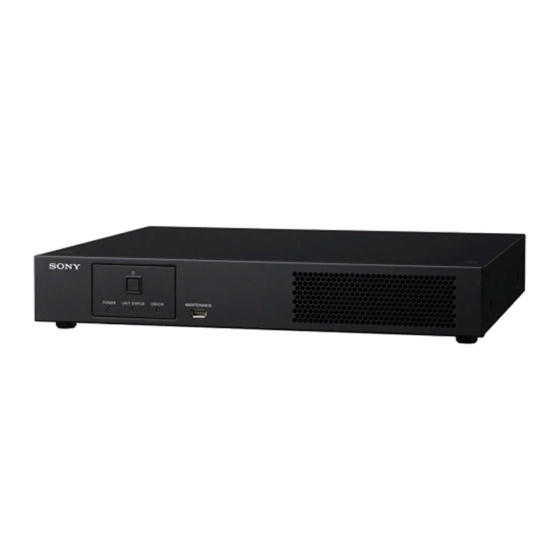
Page 5: Parts Identification
Parts Identification ZRD-1/ZRD-2 Display Unit Left / rear c - IN (AC power input) connector Caution Use a power cord (supplied with the ZRD-2 only) to connect this connector to the - OUT (AC power Do not connect the OUT and IN connectors to a hub. The... -
Page 6: Zrct-100/Zrct-200 Display Controller
f - OUT (AC power output) connector This connector is not used for the last display unit in Use a power cord (supplied with the ZRD-2 only) to the daisy-chain connection. connect this connector to the - IN (AC power input) connector on the succeeding display unit in the daisy- chain connection. - Page 7 Rear ZRCT-100 ZRCT-200 f - IN (AC power input) connector Caution Use a power cord (not supplied) to connect this Do not connect the UNIT OUTPUT, LINK IN, and LINK connector to the circuit breaker. OUT connectors to a hub. The input/output signals for these connectors are unique to the product and are not (earth) terminal Ethernet signals.
-
Page 8: Turning The Power On/Off
l DVI (video input) connectors 1 to 4 (ZRCT-100 Turning the Power On/Off only) Connect these to the video processor. m DisplayPort (video input) connectors 1 and 2 Turning the Power On Connect these to the video processor. You can turn on the system’s power using one of three n HDMI (video input) connectors 1 and 2 (ZRCT- methods. -
Page 9: Turning The Power Off
When a display controller turns on, its POWER Note indicator will switch from blinking red/orange to If you press the power switch only once in the power remaining lit green. ON state, the POWER indicator will blink red for When a display unit turns on, its status indicator lights 2 seconds, but the standby mode will not be entered. -
Page 10: Selecting The Video Input
DVI connector 1 DVI connector 3 Selecting the Video Input Select the video signals that will be input. The settings configured on the primary controller will be applied to all the other display controllers, including the subordinate controllers (hereafter referred to as “sub controllers”). -
Page 11: Changing The Display Starting Positions Of Pictures
Click [Close]. Changing the Display Starting The [Detailed Input Settings] screen closes. Positions of Pictures You can change the display positions for each picture. Configuring the Input Level and For example, you can move a low-resolution picture from Signal Format for HDMI Inputs the top left of the screen to the center. -
Page 12: Adjusting The Picture Quality
Caution Adjusting the Picture The items in the [Common Input Settings] screen cannot Quality be configured when an input channel other than HDMI is selected in [Input Select]. Adjust the contrast, brightness, and other picture quality settings. The settings configured on the primary controller will be applied to all the other display controllers, including the sub controllers. - Page 13 setting values for [Contrast] to [Color source output. For details, refer to the Installation Temperature Settings]. If necessary, change the Manual. values for [Contrast] to [Color Temperature • [Full]: Output at 100% strength. Settings]. The setting values are identical for •...
-
Page 14: Displaying 3D Video
Version 1.20.0 or later Displaying 3D Video Note In this document, the signals for the left and right eyes are referred to as the L and R signals respectively. For details, refer to the Installation Manual. Caution 3D video display is not supported for HDMI signals. For mixed L/R signals (frame sequential mode): Video signal inputs from the DisplayPort connector (100/ [3D Dual Input Mode]: Leave this checkbox cleared if... -
Page 15: Synchronizing With External Sync Signals
Synchronizing with Troubleshooting External Sync Signals Be sure to conduct a check before requesting assistance. If the problem persists, contact your local Sony representative. Inputting External Sync Signals Checking the status of the system and Input the external sync signal to the REF IN (external... - Page 16 Entering the forced standby mode Note If the controller PC hangs, for example, you can force You can view information on a display controller by display controllers and display units into standby mode. double-clicking its controller number or by right- clicking it and selecting [Controller Info.].
-
Page 17: Error Codes
UP Board (CELL_1 to CELL_12) Connection/ Connection_Error / RS485 Check that all cables are properly connected. If the problem communication Communication / Video Input Signal / persists, contact your local Sony representative. Connection_Error / RS485 Communication / Video Input Signal Warnings Warning Category... -
Page 18: Display Controllers
Check the installation, wiring, and Display Control Software mismatch warning settings, and if a problem does not exist, turn the power off and turn it on again. If the problem persists, contact your local Sony DIF signal connection warning representative. -
Page 19: Cleaning And Storage
Cleaning and Storage Signal Formats The system supports the following video signals. Display Units 3D Inputs Caution Do not wet the surface of the display units. Frame sequential mode Daily cleaning DisplayPort (single input) • Use a soft anti-static cloth that does not produce lint Resolution Input frame Input bit... -
Page 20: Inputs Other Than 3D
HDMI port (ZRCT-200 only) Inputs Other than 3D Resolution Input frame Input bit Input color DisplayPort (single input) rate length sampling 3840 × 2160 60p/50p 8-bit RGB 4:4:4 Resolution Input bit Input color Input frame YCbCr 4:4:4 length sampling rate YCbCr 4:2:0 3840 ×... -
Page 21: Supported Signal Formats For A Single Controller
Supported Signal Formats for a Single Controller DisplayPort input DVI input (ZRCT-100 only) Single input Dual input Single input Quad input Color Resolution Frequency sampling DP1 or DP2 DP1 and DP2 One of DVI DVI 1 to 4 1 to 4 8-/10-bit 120/119.88 RGB 4:4:4... - Page 22 HDMI input (ZRCT-200 only) Resolution Frequency Color sampling Single input HDMI1 or HDMI2 RGB 4:4:4/YCbCr 4:4:4 8-/10-/12-bit 60/59.94 YCbCr 4:2:2 12-bit RGB 4:4:4/YCbCr 4:4:4 8-/10-/12-bit YCbCr 4:2:2 12-bit RGB 4:4:4/YCbCr 4:4:4 8-/10-/12-bit 1920 × 1080 30/29.97 YCbCr 4:2:2 12-bit RGB 4:4:4/YCbCr 4:4:4 8-/10-/12-bit YCbCr 4:2:2 12-bit...
- Page 23 Sony Corporation...
Need help?
Do you have a question about the ZRD-1 and is the answer not in the manual?
Questions and answers