Table of Contents
Advertisement
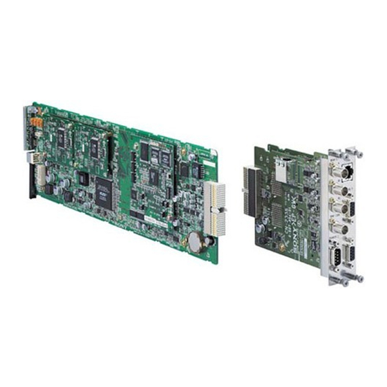
ROUTING SWITCHER CONTROLLER
HKSP-R80
ROUTING SWITCHER BACKUP CPU
HKSP-R81
! WARNING
This manual is intended for qualified service personnel only.
To reduce the risk of electric shock, fire or injury, do not perform any servicing other than that
contained in the operating instructions unless you are qualified to do so. Refer all servicing to
qualified service personnel.
! WARNUNG
Die Anleitung ist nur für qualifiziertes Fachpersonal bestimmt.
Alle Wartungsarbeiten dürfen nur von qualifiziertem Fachpersonal ausgeführt werden. Um die
Gefahr eines elektrischen Schlages, Feuergefahr und Verletzungen zu vermeiden, sind bei
Wartungsarbeiten strikt die Angaben in der Anleitung zu befolgen. Andere als die angegeben
Wartungsarbeiten dürfen nur von Personen ausgeführt werden, die eine spezielle Befähigung
dazu besitzen.
! AVERTISSEMENT
Ce manual est destiné uniquement aux personnes compétentes en charge de l'entretien. Afin
de réduire les risques de décharge électrique, d'incendie ou de blessure n'effectuer que les
réparations indiquées dans le mode d'emploi à moins d'être qualifié pour en effectuer d'autres.
Pour toute réparation faire appel à une personne compétente uniquement.
INSTALLATION MANUAL
1st Edition (Revised 4)
Serial No. 10001 and Higher (HKSP-R80)
Serial No. 20001 and Higher (HKSP-R81)
Advertisement
Table of Contents

Related Manuals for Sony HKSP-R80


Summary of Contents for Sony HKSP-R80
- Page 1 à moins d’être qualifié pour en effectuer d’autres. Pour toute réparation faire appel à une personne compétente uniquement. INSTALLATION MANUAL 1st Edition (Revised 4) Serial No. 10001 and Higher (HKSP-R80) Serial No. 20001 and Higher (HKSP-R81)
- Page 2 Kommunen. Entladen sind Batterien in der Regel dann, wenn das Gerät abschaltet und signalisiert “Batterie leer” oder nach längerer Gebrauchsdauer der Batterien “nicht mehr einwandfrei funktioniert”. Um sicherzugehen, kleben Sie die Batteriepole z.B. mit einem Klebestreifen ab oder geben Sie die Batterien einzeln in einen Plastikbeutel. HKSP-R80...
-
Page 3: Table Of Contents
19 (E) 8-1. Outline ..............19 (E) 8-1-1. Features ............. 19 (E) 8-1-2. System Connection ........... 20 (E) 8-1-3. Change of HKSP-R80 Function ...... 22 (E) 8-2. Installation of BZR-IF810 ........23 (E) 9. Backup of Setup Data ....... 26 (E) 9-1. - Page 5 (Set the rotary switch allows you to search for semiconductors used in B&P S804 to “D” and restart the HKSP-R80.) and set the time Company equipment. again (Refer to Section 2-4 of the system setup manual.).
- Page 6 *1: The following solderless contacts are required for the plug. AWG#18 to #22: 1-566-493-21 AWG#22 to #24: 1-564-774-11 AWG#24 to #30: 1-564-775-11 *2: Use shield type. USB (CPU-355 board front side) Matching cable: USB cable available on the market 2 (E) HKSP-R80...
- Page 7 4 REMOTE3 connector (D-sub 9 pin) Not used in normal operation. This connector is used for RS-232C communications. When the HKSP-R80 is set to the system primary 2 REMOTE1 (A/B1/B2) connectors (BNC type) station (S/P switch is set to P), this connector is...
- Page 8 The CPU-355 board operates as a backup CPU. (Not operating as a main CPU.) USR-DF Lights in green: When restarting the HKSP-R80, the setting data written in the flash memory as user default is enabled (S802-8 is set to ON). Off: When restarting the HKSP-R80, the previous setting data is enabled.
- Page 9 Lights in green: When data is received from the line of REMOTE2 B connector D806 (A-3) REMOTE2 B TX Lights in green: When data is transmitted to the line of REMOTE2 B connector 3 Status of the HKSP-R80 Ref. No. (Address) LED name Function...
- Page 10 5 Status of power supply block Sets the station ID of the HKSP-R80 when the HKSP-R80 is connected to the S-BUS data link as follows. Ref. No. (Address) LED name Function When the HKSP-R80 is used as the primary station, the D1201 (D-3) 2.5 V...
- Page 11 Used to select whether the S-BUS table data stored in the Set this switch when you want to enable the cross-level tie HKSP-R80 is protected or not, when the HKSP-R80 is set line function when the tie line system is constructed using as the primary station.
- Page 12 In case of setting HKSP-R80 operates as – S804 to 8, all the information set in the HKSP-R80 may be secondary station erased affecting the operation of the HKSP-R80. In case of PRIMARY...
- Page 13 Used for adjustment in the factory. of the HKSP-R80. Set this switch to 0 to return to the If this mode is executed, all of the setting data are normal operation.
- Page 14 S202 (A-2): RST 8-pin DIP switch CPU software reboot switch This switch is factory use only. Do not change this setting. Reboots only the CPU software. The default setting is all OFF. This switch does not perform FPGA reconfiguration. 10 (E) HKSP-R80...
- Page 15 D103 (A-1) 3.3 V Lights in green: Power supply of +3.3 V is normal. CN-2335 board D102 Ref. No. (Address) LED name Status during ON D102 (A-1) Lights in green: Power supply of +5 V is normal. 11 (E) HKSP-R80...
-
Page 16: Setting Network Connection (Ip Address)
The settings can be set with the included GUI software BZR-25 for network setting or with the following setting procedure. For details about installing BZR-25, see “9-2. Installing BZR-20/BZR-25”. For details about using BZR- 25, see the BZR-25 online help. To activate the BZR-25 settings, the switch S802-4 must be turned to ON. 12 (E) HKSP-R80... - Page 17 (S1201) on the CPU-355 board to return to the normal operation mode. 12. Check that the backup CPU is activated. After waiting for about 5 seconds, turn off the power and back on again or press the reset switch of the CPU-355 board to restart the main CPU. 13 (E) HKSP-R80...
-
Page 18: System Connection
*: (P) and (S) indicate the setting of the S/P selector switch on the CPU board in the controller and routing switcher. Switchers other than the HKSP-R80 can be also set as a primary station. In this case, some functions are limited. - Page 19 The following diagram shows an example of the connection for the data link of the S-BUS when the HKSP-R80 is set as a primary station. Maximum 16 equipment : S-BUS Terminal Terminal : Signal system line Personal computer Personal computer...
-
Page 20: Recommended Ethernet Switch
. In the secondary controller and routing switcher, only one REMOTE 1 connector can be used each. How to use the T-type bridge The B type of T-type bridge is supplied with the HKSP-R80. Prepare coaxial cable (BELDEN 8281) of 50 cm or less and use the T-type bridge as follows. -
Page 21: Error Indication
When there is no error, “R80” is displayed on the status indicator. On similar occasions, when the BZR- IF810 is installed in the HKSP-R80, “810” is displayed. (The STATUS indicator lights in green.) For the error message displayed on the personal computer (terminal emulator) connected to the RE- MOTE3 connector or DATA connector, refer to the system setup manual supplied with the HKSP-R80. -
Page 22: Input And Output Signals Of Connectors
REMOTE3 : RS-232C (D-sub 9-pin, Male) _ EXT VIEW _ Pin No. Signal name Input/Output Function Date carrier detect Received data Transmitted data Data terminal ready Signal ground Date set ready Request to send Clear to send No connection 18 (E) HKSP-R80... -
Page 23: About Supplied Software Bzr-If810
The S-BUS subnet controller software BZR-IF810 is software installed on the routing switcher controller Improving the response time for operation and HKSP-R80 to construct an S-BUS subnet. The HKSP-R80 display on which the BZR-IF810 is installed is referred to as an S- Response time for tally data sent to the UMD is improved BUS subnet controller in this manual. -
Page 24: System Connection
Signal processing unit PFV-SP series RS-232C (or Ethernet) Routing switcher Control terminal Routing switcher REMOTE3 controller controller (or DATA connector) HKSP-R80 HKSP-R80 (with BZR-IF810 installed) Secondary station Signal processing unit PFV-SP series REMOTE1 B1, B2 Routing switcher S-BUS subnet control unit... - Page 25 Primary station Signal processing unit PFV-SP series Control terminal Routing switcher (with BZR-20 installed) controller RS-232C (or Ethernet) Performs the HKSP-R80 REMOTE3 (or DATA connector) setting of the primary and secondary stations. Secondary station Routing switcher Routing switcher Routing switcher max.
-
Page 26: Change Of Hksp-R80 Function
When the BZR-IF810 is installed, the HKSP-R80 functions as an S-bus subnet controller as described below. Function (S-BUS subnet controller) If BZR-IF810 is installed on a HKSP-R80, it functions as the secondary station, and the functions of the REMOTE1 A and B connectors are separated. The REMOTE1 A connector is for connection with the primary station, and the REMOTE1 B1 and B2 connectors are for connection with the third-level stations. -
Page 27: Installation Of Bzr-If810
SYNC/ASYNC selector switch 2. Set S803-3 to ON. . BIT4: Table data size selector switch . BIT5, BIT6: Baud rate selector switches Switches other than S803-3 are not reflected on the setting. . BIT8: A2 channel valid/invalid switch 23 (E) HKSP-R80... - Page 28 If the CPU-355 board fails to start up for this reason, contact your local Sony Sales Office/Service Center. 9. Terminate the terminal software. 24 (E)
- Page 29 4. Turn the power off and back on. Check that the system status screen appears on the display. Check also that “BZR-IF810” is displayed in the top line as the model name. SONY ROUTING SYSTEM BZR-IF810 V1.00 ITEM ROM CHECK SUM A43F...
-
Page 30: Backup Of Setup Data
RAM on the CPU-355 board. Backing up the stored data is recommended in the case of emergency such as data are damaged or lost. Backing up the stored data is performed using the software BZR-20 supplied with the HKSP-R80. 9-1. Connection Connect the equipment as shown below for uploading and downloading the stored data. -
Page 31: Installing Bzr-20/Bzr-25
The copied files are not needed after installation. The files can be deleted. . Windows is a registered trademark of Microsoft Corporation. . IBM and AT are registered trademarks of International Business Machine Corporation. . Pentium is a registered trademark of Intel Corporation. 27 (E) HKSP-R80... -
Page 32: Uploading The Data
2. Turn on the power of all the equipment on the S-BUS data link. 3. Connect the PC to the REMOTE3 connector or the DATA connector of the HKSP-R80 (or connect the PC to each equipment). (Refer to Section 9-1.) 4. -
Page 33: Downloading The Data
S- 1. Install the BZR-20 software. (Refer to Section 9-2.) BUS subnet controller in the above description. 2. Connect the PC to the HKSP-R80 (or connect the PC to each equipment) and start up the BZR-20 software. 10. Lithium Battery (Refer to Section 9-3, steps 2 to 5.) - Page 34 If the timeout time is set to 0, it means the timeout time is infinite. When the timeout is set to 0 and you quit HKSP-R80 without shutting down the connection between the PC and HKSP-R80 that has already been connected before using Ethernet, the correspond- ing port is left open and cannot be closed except by a hardware reset.
- Page 35 (Common between HKSP- R80/R81) DATA (RJ-45 modular jack type) Approx. 500 g Signal format Conforms to 10BASE-T/ Connector board: 100BASE-TX (Only for HKSP-R80) Approx. 400 g TIME CODE (BNC type) Power requirements +12 V dc Signal format Conforms to SMPTE/EBU Power consumption 1.0 A (HKSP-R80)
- Page 38 The material contained in this manual consists of information that is the property of Sony Corporation. Sony Corporation expressly prohibits the duplication of any portion of this manual or the use thereof for any purpose other than the operation or maintenance of the equipment described in this manual without the express written permission of Sony Corporation.
Need help?
Do you have a question about the HKSP-R80 and is the answer not in the manual?
Questions and answers