Crown Boiler AWR Series Installation Instructions Manual
Gas-fired natural draft hot water boilers
Hide thumbs
Also See for AWR Series:
- Instructions for field conversion (12 pages) ,
- Installation instructions manual (51 pages)
Advertisement
Table of Contents
- 1 Table of Contents
- 2 Product Description
- 3 Specifications
- 4 Pre-Installation
- 5 Locating the Boiler
- 6 Air for Combustion & Ventilation
- 7 Venting
- 8 System Piping
- 9 Gas Piping
- 10 Wiring
- 11 Start-Up & Checkout
- 12 Operation
- 13 Service & Maintenance
- 14 Troubleshooting
- 15 Parts
- 16 Appendix A. Instructions for High Altitude Installations (US Only)
- Download this manual
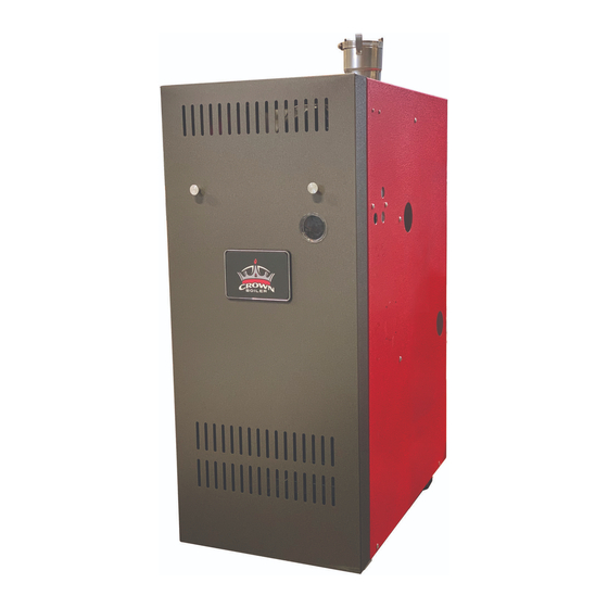
AWR Series
Gas-Fired Natural Draft Hot Water Boilers
INSTALLATION INSTRUCTIONS
These instructions must be affixed on or adjacent to the boiler
Models:
AWR038B
•
AWR070B
•
AWR105B
•
AWR140B
•
AWR175B
•
AWR210B
•
AWR245B
•
AWR280B
•
Models Equipped with
Honeywell S9361A and
Hydrolevel IDL 1200
LWCO (5.1)
9807815 Rev 0, 04-21
D
E S I G N E D
Manufacturer of Hydronic Heating Products
P.O. Box 14818 3633 I. Street
Philadelphia, PA 19134
www.crownboiler.com
L
T O
E A D
Improper installation, adjustment, alteration,
service or maintenance can cause property
damage, injury, or loss of life. For assistance
or additional information, consult a qualified
installer, service agency or the gas supplier.
This boiler requires a special venting system.
Read these instructions carefully before
installing.
1
!
WARNING
9902339
Advertisement
Table of Contents


Need help?
Do you have a question about the AWR Series and is the answer not in the manual?
Questions and answers