
Related Manuals for VIPA CPU 312SC


Summary of Contents for VIPA CPU 312SC
- Page 1 VIPA System 300S CPU-SC | 312-5BE13 | Manual HB140 | CPU-SC | 312-5BE13 | GB | 15-50 SPEED7 CPU 312SC...
- Page 2 VIPA GmbH Ohmstr. 4 91074 Herzogenaurach Telephone: +49 9132 744-0 Fax: +49 9132 744-1864 Email: info@vipa.com Internet: www.vipa.com 312-5BE13_000_CPU-SC 312SC,1,GB - © 2015...
-
Page 3: Table Of Contents
VIPA System 300S Table of contents Table of contents General..................6 1.1 Copyright © VIPA GmbH ........... 6 1.2 About this manual.............. 7 1.3 Safety information.............. 8 Basics..................10 2.1 Safety information for users..........10 2.2 Operating structure of a CPU........... 10 2.2.1 General................. - Page 4 5.16 Memory extension with MCC......... 68 5.17 Extended know-how protection........69 5.18 MMC-Cmd - Auto commands......... 70 5.19 VIPA specific diagnostic entries........72 5.20 Control and monitoring of variables with test functions.. 88 Deployment I/O periphery............. 90 6.1 Overview................90 6.2 In-/Output area CPU 312-5BE13........
- Page 5 9.3 TIA Portal - Hardware configuration - I/O modules..179 9.4 TIA Portal - Hardware configuration - Ethernet PG/OP channel................180 9.5 TIA Portal - Include VIPA library........183 9.6 TIA Portal - Project transfer..........183 HB140 | CPU-SC | 312-5BE13 | GB | 15-50...
-
Page 6: General
General 1.1 Copyright © VIPA GmbH All Rights Reserved This document contains proprietary information of VIPA and is not to be disclosed or used except in accordance with applicable agree- ments. This material is protected by the copyright laws. It may not be repro-... -
Page 7: About This Manual
Tel.: +49 9132 744-1150 (Hotline) EMail: support@vipa.de 1.2 About this manual Objective and contents This manual describes the SPEED7 CPU-SC 312-5BE13 of the System 300S from VIPA. It contains a description of the construction, project implementation and usage. Product Order number as of state:... -
Page 8: Safety Information
General VIPA System 300S Safety information Guide to the document The following guides are available in the manual: An overall table of contents at the beginning of the manual References with page numbers Availability The manual is available in: printed form, on paper... - Page 9 VIPA System 300S General Safety information CAUTION! The following conditions must be met before using or commissioning the components described in this manual: – Hardware modifications to the process control system should only be carried out when the system has been disconnected from power! –...
-
Page 10: Basics
Operating structure of a CPU > General Basics 2.1 Safety information for users Handling of electro- VIPA modules make use of highly integrated components in MOS- static sensitive modules Technology. These components are extremely sensitive to over-vol- tages that can occur during electrostatic discharges. The following symbol is attached to modules that can be destroyed by electrostatic discharges. -
Page 11: Applications
VIPA System 300S Basics Operating structure of a CPU > Operands Cyclic processing Cyclicprocessing represents the major portion of all the processes that are executed in the CPU. Identical sequences of operations are repeated in a never-ending cycle. Timer processing Where a process requires control signals at constant intervals you can initiate certain operations based upon a timer, e.g. -
Page 12: Cpu 312-5Be13
SIMATIC Manager or TIA Portal from Siemens. Here the instruction set of the S7-400 from Siemens is used. Modules and CPUs of the System 300S from VIPA and Siemens may be used at the bus as a mixed configuration. -
Page 13: General Data
VIPA System 300S Basics General data Memory The CPU has an integrated memory. Information about the capacity of the memory may be found at the front of the CPU. The memory is divided into the following parts: Load memory 512kbyte... - Page 14 Basics VIPA System 300S General data Conformity and approval others RoHS 2011/65/EU Product is lead-free; Restriction of the use of certain hazardous substances in electrical and electronic equipment Protection of persons and device protection Type of protection IP20 Electrical isolation...
- Page 15 VIPA System 300S Basics General data Standard Comment Emitted interfer- EN 61000-6-4 Class A (Industrial area) ence Noise immunity EN 61000-6-2 Industrial area zone B EN 61000-4-2 8kV at air discharge (degree of severity 3), 4kV at contact discharge (degree of severity...
-
Page 16: Assembly And Installation Guidelines
Assembly and installation guidelines VIPA System 300S Installation dimensions Assembly and installation guidelines 3.1 Installation dimensions Dimensions Basic 2tier width (WxHxD) in mm: 80 x 125 x 120 enclosure Dimensions Installation dimensions HB140 | CPU-SC | 312-5BE13 | GB | 15-50... -
Page 17: Assembly Standard Bus
VIPA System 300S Assembly and installation guidelines Assembly standard bus 3.2 Assembly standard bus General The single modules are directly installed on a profile rail and con- nected via the backplane bus connector. Before installing the modules you have to clip the backplane bus connector to the module from the backside. -
Page 18: Cabling
Assembly and installation guidelines VIPA System 300S Cabling Assembly possibilities Please regard the allowed environment temperatures: horizontal assembly: from 0 to 60°C vertical assembly: from 0 to 50°C lying assembly: from 0 to 55°C Approach Bolt the profile rail with the background (screw size: M6), so that you still have minimum 65mm space above and 40mm below the profile rail. - Page 19 VIPA System 300S Assembly and installation guidelines Cabling CageClamp technology For the cabling of power supply of a CPU, a green plug with Cage- (green) Clamp technology is deployed. The connection clamp is realized as plug that may be clipped off carefully if it is still cabled.
- Page 20 Assembly and installation guidelines VIPA System 300S Cabling 20pole screw connec- tion 392-1AJ00 Open the front flap of your I/O module. Bring the front connector in cabling position. For this you plug the front connector on the module until it locks.
-
Page 21: Installation Guidelines
VIPA System 300S Assembly and installation guidelines Installation guidelines 40pole screw connec- tion 392-1AM00 Open the front flap of your I/O module. Bring the front connector in cabling position. For this you plug the front connector on the module until it locks. - Page 22 The components of VIPA are developed for the deployment in indus- trial environments and meets high demands on the EMC. Neverthe- less you should project an EMC planning before installing the compo- nents and take conceivable interference causes into account.
- Page 23 VIPA System 300S Assembly and installation guidelines Installation guidelines In special use cases you should appoint special EMC actions. – Consider to wire all inductivities with erase links. – Please consider luminescent lamps can influence signal lines. Create a homogeneous reference potential and ground all elec- trical operating supplies when possible.
-
Page 24: Hardware Description
Hardware description VIPA System 300S Properties Hardware description 4.1 Properties CPU 312-5BE13 SPEED7 technology integrated 64kbyte work memory integrated (32kbyte code, 32kbyte data) Work memory expandable to max. 512Mbyte (256kbyte code, 256kbyte data) 512kbyte load memory RS485 interface for PtP communication... -
Page 25: Structure
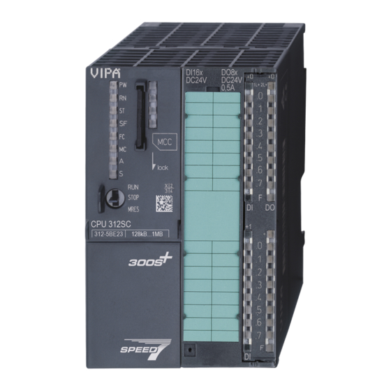
VIPA System 300S Hardware description Structure > General 4.2 Structure 4.2.1 General CPU 312-5BE13 1 LEDs of the CPU part 2 Storage media slot (lockable) 3 LEDs of the I/O part 4 Operating mode switch CPU 5 Slot for DC 24V power supply... -
Page 26: Interfaces
Hardware description VIPA System 300S Structure > Interfaces 4.2.2 Interfaces X1: Power supply The CPU has an integrated power supply: The power supply has to be provided with DC 24V. For this serves the double DC 24V slot, that is underneath the flap. - Page 27 VIPA System 300S Hardware description Structure > Interfaces The CPU has a PtP interface. The interface is fix set to PtP communi- cation. PtP functionality – Using the PtP functionality the RS485 interface is allowed to connect via serial point-to-point connection to different source res.
-
Page 28: In-/Output Area Cpu 312-5Be13
Hardware description VIPA System 300S Structure > In-/Output area CPU 312-5BE13 4.2.3 In-/Output area CPU 312-5BE13 Overview The CPU 312-5BE13 has the following digital in and output channels integrated in one casing: Digital Input: 16xDC 24V, with interrupt capability Digital Output: 8xDC 24V, 0.5A... - Page 29 VIPA System 300S Hardware description Structure > In-/Output area CPU 312-5BE13 Pin assignment X11: DI Assignment 1L+ Power supply +DC 24V I+0.0 / Channel 0 (A) / Pulse I+0.1 / Channel 0 (B) / Direction I+0.2 / Channel 0 HW gate I+0.3 / Channel 1 (A) / Pulse...
- Page 30 Hardware description VIPA System 300S Structure > In-/Output area CPU 312-5BE13 Status indication X11: DI – LED (green) Supply voltage available for DI .0 ..7 – LEDs (green) I+0.0 ... I+0.7 I+1.0 ... I+1.7 Starting with ca. 15V the signal "1" at the input is recognized...
-
Page 31: Memory Management
As external storage medium for applications and firmware you may use a MMC storage module (Multimedia card). The VIPA storage media are pre-formatted with the PC format FAT16 and can be accessed via a card reader. After PowerON respectively an overall reset the CPU checks, if there is a storage medium with data valid for the CPU. -
Page 32: Battery Backup For Clock And Ram
Hardware description VIPA System 300S Structure > Operating mode switch CAUTION! If the media was already unlocked by the spring mecha- nism, with shifting the sliding mechanism, a just installed memory card can jump out of the slot! 4.2.6 Battery backup for clock and RAM A rechargeable battery is installed on every CPU to safeguard the contents of the RAM when power is removed. -
Page 33: Leds
VIPA System 300S Hardware description Structure > LEDs 4.2.8 LEDs LEDs CPU As soon as the CPU is supplied with 5V, the green PW-LED (Power) is on. Meaning (RUN) (STOP) (SFAIL) (FRCE) (MMC) green yellow yellow yellow Boot-up after PowerON ●... -
Page 34: Technical Data
Hardware description VIPA System 300S Technical data Meaning (RUN) (STOP) (SFAIL) (FRCE) (MMC) ○ * Blinking with 10Hz: Error during Firmware update. on: ● | off: ○ | blinking (2Hz): BB | not relevant: X LEDs Ethernet PG/OP channel L/A, S The green L/A-LED (Link/Activity) indicates the physical connection of the Ethernet PG/OP channel to Ethernet. - Page 35 VIPA System 300S Hardware description Technical data Order no. 312-5BE13 Current consumption from load voltage L+ 70 mA (without load) Rated value DC 24 V Input voltage for signal "0" DC 0...5 V Input voltage for signal "1" DC 15...28.8 V...
- Page 36 Hardware description VIPA System 300S Technical data Order no. 312-5BE13 Output current at signal "0" max. (residual cur- 0.5 mA rent) Output delay of "0" to "1" 100 µs Output delay of "1" to "0" 100 µs Minimum load current...
- Page 37 VIPA System 300S Hardware description Technical data Order no. 312-5BE13 Input current ranges Operational limit of current ranges Operational limit of current ranges with SFU Basic error limit current ranges Radical error limit current ranges with SFU Destruction limit current inputs (electrical cur-...
- Page 38 Hardware description VIPA System 300S Technical data Order no. 312-5BE13 Resolution in bit Measurement principle Basic conversion time Noise suppression for frequency Initial data size Technical data analog outputs Number of outputs Cable length, shielded Rated load voltage Reverse polarity protection of rated load...
- Page 39 VIPA System 300S Hardware description Technical data Order no. 312-5BE13 Output data size Technical data counters Number of counters Counter width 32 Bit Maximum input frequency 10 kHz Maximum count frequency 10 kHz Mode incremental encoder ü Mode pulse / direction ü...
- Page 40 Hardware description VIPA System 300S Technical data Order no. 312-5BE13 Diagnostics information read-out possible Supply voltage display green LED Group error display red SF LED Channel error display red LED per group Isolation Between channels ü Between channels of groups to Between channels and backplane bus ü...
- Page 41 VIPA System 300S Hardware description Technical data Order no. 312-5BE13 Maximum nesting depth per priority class Maximum nesting depth additional within an error OB Time Real-time clock buffered ü Clock buffered period (min.) Accuracy (max. deviation per day) 10 s...
- Page 42 Hardware description VIPA System 300S Technical data Order no. 312-5BE13 S7 communication as server ü S7 communication as client S7 communication, user data per job 160 Byte Number of connections, max. PWM data PWM channels PWM time basis 0.1ms/1ms Period length 4...65535 / 1...65535 * timebase...
- Page 43 VIPA System 300S Hardware description Technical data Order no. 312-5BE13 S7 communication ü S7 communication as server ü S7 communication as client Transmission speed, min. 19.2 kbit/s Transmission speed, max. 187.5 kbit/s Functionality PROFIBUS master PG/OP channel Routing S7 basic communication...
- Page 44 Hardware description VIPA System 300S Technical data Order no. 312-5BE13 Address areas, max. User data per address area, max. Point-to-point communication PtP communication ü Interface isolated ü RS232 interface RS422 interface RS485 interface ü Connector Sub-D, 9-pin, female Transmission speed, min.
- Page 45 VIPA System 300S Hardware description Technical data Order no. 312-5BE13 Operating temperature 0 °C to 60 °C Storage temperature -25 °C to 70 °C Certifications UL certification HB140 | CPU-SC | 312-5BE13 | GB | 15-50...
-
Page 46: Deployment Cpu 312-5Be13
Deployment CPU 312-5BE13 VIPA System 300S Start-up behavior Deployment CPU 312-5BE13 5.1 Assembly Ä Chapter 3 Information about assembly and cabling: ‘Assembly and installation guidelines’ on page 16 5.2 Start-up behavior Turn on power supply After the power supply has been switched on, the CPU changes to the operating mode the operating mode lever shows. -
Page 47: Addressing
VIPA System 300S Deployment CPU 312-5BE13 Addressing > Addressing Backplane bus I/O devices 5.3 Addressing 5.3.1 Overview To provide specific addressing of the installed peripheral modules, certain addresses must be allocated in the CPU. At the start-up of the CPU, this assigns automatically peripheral addresses for digital in-/ output modules starting with 0 and ascending depending on the slot location. -
Page 48: Address Assignment
Deployment CPU 312-5BE13 VIPA System 300S Address assignment Example for automatic The following sample shows the functionality of the automatic address allocation address allocation: 5.4 Address assignment Input area Default Access Assignment module address DI10/DO6 Byte Digital input I+0.0 ... I+0.7 Byte Digital input I+1.0 ... -
Page 49: Hardware Configuration - Cpu
MOD, +R, -R, *R, /R) the content of ACCU 3 and ACCU 4 is loaded into ACCU 3 and 2. This may cause conflicts in applications that presume an unmodified ACCU 2. For more information may be found in the manual "VIPA Operation list SPEED7" at "Differences between SPEED7 and 300V programming". -
Page 50: Hardware Configuration - I/O Modules
Deployment CPU 312-5BE13 VIPA System 300S Hardware configuration - Ethernet PG/OP channel 5.6 Hardware configuration - I/O modules Hardware configuration After the hardware configuration place the System 300 modules in the of the modules plugged sequence starting with slot 4. - Page 51 VIPA System 300S Deployment CPU 312-5BE13 Hardware configuration - Ethernet PG/OP channel "Initialization" via PLC The initialization via PLC functions takes place with the following pro- functions ceeding: Determine the current Ethernet (MAC) address of your Ethernet PG/OP channel. This always may be found as 1. address under the front flap of the CPU on a sticker on the left side.
-
Page 52: Cpu Parametrization
Deployment CPU 312-5BE13 VIPA System 300S CPU parametrization > CPU parameters Transfer your project. 5.8 CPU parametrization 5.8.1 Parametrization via Siemens CPU Parameterization via Since the CPU is to be configured as Siemens CPU 312C (CPU Siemens CPU 312C 312-5BE03-0AB0 V2.6) in the Siemens hardware configurator, the parameters of the CPU 312-5BE13 may be set with "Object proper-... - Page 53 OB85 call up at I/O access error: The preset reaction of the CPU may be changed to an I/O access error that occurs during the update of the process image by the system. The VIPA CPU is preset such that OB 85 is not called if an I/O access error occurs and no entry is made in the diagnostic buffer either.
-
Page 54: Project Transfer
Deployment CPU 312-5BE13 VIPA System 300S Project transfer Retentive Memory Number of Memory bytes from MB0: Enter the number of retentive memory bytes from memory byte 0 onwards. Number of S7 Timers from T0: Enter the number of retentive S7 timers from T0 onwards. -
Page 55: Transfer Via Mpi
Please consider with the CPU 312-5BE13 that the total exten- sion of the MPI net does not exceed 50m. Per default the MPI net runs with 187.5kbaud. VIPA CPUs are delivered with MPI address 2. MPI programming cable The MPI programming cables are available at VIPA in different var- iants. -
Page 56: Transfer Via Ethernet
Deployment CPU 312-5BE13 VIPA System 300S Project transfer > Transfer via MMC 5.9.2 Transfer via Ethernet For transfer via Ethernet the CPU has the following interface: X5: Ethernet PG/OP channel Initialization So that you may access the Ethernet PG/OP channel you have to assign IP address parameters by means of the "initialization". -
Page 57: Access To The Internal Web Page
CPU. To monitor the diagnosis entries, you select ‘PLC è Module Information’ in the Siemens SIMATIC Manager. Via the register "Diagnostic Buffer" you reach the diagnosis window. Ä Chapter 5.19 ‘VIPA specific diag- Information about the event IDs nostic entries’ on page 72. - Page 58 The access takes place via the IP address of the Ethernet PG/OP channel. The web page only serves for information output. The moni- tored values are not alterable. CPU with Ethernet-PG/OP Slot 100 VIPA 312-5BE13 V..Px000135.pkg, Order no., firmware vers., package, serial no. SERIALNUMBER 05439 SUPPORTDATA :...
-
Page 59: Operating Modes
Configured input base addresses Address Output 124...124 Configured output base addresses Slot 204 CPU component: Counter VIPA 2 COUNTERS V3.2.9, Name, firmware version, module type SUPPORTDATA: PRODUCT V3290, Module Type ... Information for support Address Input 768...783 Configured input base addresses Address Output 768...783... - Page 60 Deployment CPU 312-5BE13 VIPA System 300S Operating modes > Overview RUN-LED blinks as soon as the OB 100 is operated and for at least 3s, even if the start-up time is shorter or the CPU gets to STOP due to an error.
-
Page 61: Function Security
(parametrizable min. 1ms) that stop res. execute a RESET at the CPU in case of an error and set it into a defined STOP state. The VIPA CPUs are developed function secure and have the following system properties:... -
Page 62: Overall Reset
Deployment CPU 312-5BE13 VIPA System 300S Overall reset 5.12 Overall reset Overview During the overall reset the entire user memory is erased. Data located in the memory card is not affected. You have 2 options to ini- tiate an overall reset:... -
Page 63: Firmware Update
Latest firmware at The latest firmware versions are to be found in the service area at www.vipa.com www.vipa.com. For example the following files are necessary for the firmware update of the CPU 312-5BE13 and its components with hardware release 1: 312-5BE13, Hardware release 1: Px000135.pkg... - Page 64 Via the register ‘General’ the window with hardware and firm- ware version may be selected. ð Due to software-technical reasons there is something dif- ferent of the VIPA CPU 312-5BE13 to the CPU 312C from Siemens: 1 VIPA order no. (VIPA 312-5BE13)
- Page 65 VIPA System 300S Deployment CPU 312-5BE13 Firmware update Every register of the module information dialog is sup- ported by the VIPA CPUs. More about these registers may be found in the online help of the Siemens SIMATIC man- ager. Load firmware and Go to www.vipa.com...
-
Page 66: Reset To Factory Setting
Deployment CPU 312-5BE13 VIPA System 300S Reset to factory setting Turn Power OFF and ON. Now it is checked by the CPU, whether further current firmware versions are available at the MMC. If so, again the LEDs SF and FC flash after a short start- up period. -
Page 67: Slot For Storage Media
VIPA System 300S Deployment CPU 312-5BE13 Slot for storage media The proceeding is shown in the following Illustration: After the firmware update you always should execute a Reset to factory setting. 5.15 Slot for storage media Overview At the front of the CPU there is a slot for storage media. As external storage medium for applications and firmware you may use a multi- media card (MMC). -
Page 68: Memory Extension With Mcc
Overview There is the possibility to extend the work memory of the CPU. For this, a MCC memory extension card is available from VIPA. The MCC is a specially prepared MMC (Multimedia Card). By plugging the MCC into the MCC slot and then an overall reset the according memory expansion is released. -
Page 69: Extended Know-How Protection
Extended know-how protection Overview Besides the "standard" Know-how protection the SPEED7-CPUs from VIPA provide an "extended" know-how protection that serves a secure block protection for accesses of 3. persons. Standard protection The standard protection from Siemens transfers also protected blocks to the PG but their content is not displayed. -
Page 70: Mmc-Cmd - Auto Commands
Deployment CPU 312-5BE13 VIPA System 300S MMC-Cmd - Auto commands Protection behavior Protected blocks are overwritten by a new protect.wld. Using a PG 3. persons may access protected blocks but only the block header is transferred to the PG. The block code that is to be protected remains in the CPU and cannot be read. - Page 71 VIPA System 300S Deployment CPU 312-5BE13 MMC-Cmd - Auto commands Command Description Diagnostics entry SAVE_PROJECT The recent project (blocks and hardware config- 0xE806 uration) is stored as "s7prog.wld" at the MMC.If the file just exists it is renamed to "s7prog.old".
-
Page 72: Vipa Specific Diagnostic Entries
You may read the diagnostic buffer of the CPU via the Siemens nostic buffer SIMATIC Manager. Besides of the standard entries in the diagnostic buffer, the VIPA CPUs support some additional specific entries in form of event-IDs. The current content of the diagnostics buffer is stored at the memory card by means of the CMD DIAGBUFF. - Page 73 The diagnosis is independent from the operating mode of the CPU. You may store a max. of 100 diagnostic entries in the CPU. The fol- lowing page shows an overview of the VIPA specific Event-IDs. Overview of the Event-IDs Event-ID...
- Page 74 0xE020 Error - Interrupt information is not defined 0xE030 Error of the standard bus 0xE033 Internal error - Please contact the VIPA Hotline! 0xE0B0 SPEED7 is not stoppable (Probably undefined BCD value at timer) 0xE0C0 Not enough space in work memory for storing code block (block size...
- Page 75 ZInfo1: Periphery address ZInfo3: 0: Periphery address is input, 1: Periphery address is output 0xE701 Internal error - Please contact the VIPA Hotline! 0xE703 Internal error - Please contact the VIPA Hotline! 0xE720 Internal error - Please contact the VIPA Hotline!
- Page 76 CMD - Auto command: Error: Error while reading CMD file (memory card error) 0xE901 Check sum error 0xEA00 Internal error - Please contact the VIPA Hotline! 0xEA01 Internal error - Please contact the VIPA Hotline! 0xEA02 SBUS: Internal error (internal plugged sub module not recognized)
- Page 77 ZInfo1: Periphery address ZInfo2: Slot ZInfo3: Data width 0xEA15 Internal error - Please contact the VIPA Hotline! 0xEA18 SBUS: Error at mapping of the master periphery ZInfo2: Slot of the master 0xEA19 Internal error - Please contact the VIPA Hotline!
- Page 78 Error - PROFINET IO controller reports multiple parametrization of a periphery address ZInfo1: Periphery address ZInfo2: User slot of the PROFINET I/O controller ZInfo3: Data width 0xEA61 ... 0xEA63 Internal error - Please contact the VIPA Hotline! HB140 | CPU-SC | 312-5BE13 | GB | 15-50...
- Page 79 Bit 14: CPU is configured as I device Bit 15: Obtain an IP address in a different way is not supported for the IP address of the controller 0xEA65 Internal error - Please contact the VIPA Hotline! 0xEA66 PROFINET IO controller Error in communication stack PK: Rackslot OBNr: StackError.Service...
- Page 80 OBNo: PROFINET IO controller slot DatId: Device-No. ZInfo1: Record set number ZInfo2: Record set handle ZInfo3: Internal error code for service purposes 0xEA69 Internal error - Please contact the VIPA Hotline! 0xEA6A PROFINET IO controller Service error in communication stack PK: Rackslot OBNo: ServiceIdentifier DatId: 0 ZInfo1: ServiceError.Code...
- Page 81 VIPA System 300S Deployment CPU 312-5BE13 VIPA specific diagnostic entries Event-ID Description 0xEA6D PROFINET IO controller No empty name PK: Rackslot OBNo: PLC Mode DatId: 0 ZInfo1: Device ID ZInfo2: - ZInfo3: - 0xEA6E PROFINET IO controller RPC response missing...
- Page 82 Deployment CPU 312-5BE13 VIPA System 300S VIPA specific diagnostic entries Event-ID Description 0xEAA0 Emac Error occurred OBNo: Current PLC mode ZInfo1: Diagnostics address of the master / controller ZInfo2: 0: None Rx queue is full 1: No send buffer available 2: Send stream was cut off;...
- Page 83 VIPA System 300S Deployment CPU 312-5BE13 VIPA specific diagnostic entries Event-ID Description 0xEC03 EtherCAT: Configuration error ZInfo1: Errorcode 1: NUMBER_OF_SLAVES_NOT_SUPPORTED 2: SYSTEM_IO_NR_INVALID 3: INDEX_FROM_SLOT_ERROR 4: MASTER_CONFIG_INVALID 5: MASTER_TYPE_ERROR 6: SLAVE_DIAG_ADDR_INVALID 7: SLAVE_ADDR_INVALID 8: SLAVE_MODULE_IO_CONFIG_INVALID 9: LOG_ADDR_ALREADY_IN_USE 10: NULL_PTR_CHECK_ERROR 11: IO_MAPPING_ERROR...
- Page 84 Deployment CPU 312-5BE13 VIPA System 300S VIPA specific diagnostic entries Event-ID Description 0xEC11 EtherCAT: Restoration bus with missing slaves OB start Info (Local data) StartEvent and Eventclass: 0xEC11 DatID: 0xXXYY: XX=0x54 with input address in ZInfo1, XX=0x55 with output address.
- Page 85 VIPA System 300S Deployment CPU 312-5BE13 VIPA specific diagnostic entries Event-ID Description 0xED12 EtherCAT: Failure slave OB start Info (Local data) StartEvent and Eventclass: 0xED12 DatID: 0xXXYY: XX=0x54 with input address in ZInfo1, XX=0x55 with output address. YY=0x00 Station not available,...
- Page 86 EtherCAT: Interrupt Queue Overflow OB start Info (Local data) StartEvent and Eventclass: 0xED31 ZInfo2: Diagnostics address of the master 0xED40 ... 0xED4F Internal error - Please contact the VIPA Hotline! 0xED50 EtherCAT: DC not in Sync ZInfo1: Diagnostics address of the master...
- Page 87 Internal error - Please contact the VIPA Hotline! 0xEEEE CPU was completely overall reset, since after PowerON the start-up could not be finished. 0xEF11 ... 0xEF13 Internal error - Please contact the VIPA Hotline! HB140 | CPU-SC | 312-5BE13 | GB | 15-50...
-
Page 88: Control And Monitoring Of Variables With Test Functions
VIPA System 300S Control and monitoring of variables with test functions Event-ID Description 0xEFFF Internal error - Please contact the VIPA Hotline! PK: C-Source module number | DatID: Line number 5.20 Control and monitoring of variables with test functions Overview... - Page 89 VIPA System 300S Deployment CPU 312-5BE13 Control and monitoring of variables with test functions Control of outputs – It is possible to check the wiring and proper operation of output modules. – You can set outputs to any desired status with or without a control program.
-
Page 90: Deployment I/O Periphery
Deployment I/O periphery VIPA System 300S Overview Deployment I/O periphery 6.1 Overview Hardware At the 312-5BE13 the connectors for digital in-/output and technolog- ical functions are integrated to a 2tier casing. Project engineering The project engineering takes place in the Siemens SIMATIC man- ager as CPU 312C from Siemens (6ES7 312-5BE03-0AB0 V2.6). -
Page 91: In-/Output Area Cpu 312-5Be13
VIPA System 300S Deployment I/O periphery In-/Output area CPU 312-5BE13 6.2 In-/Output area CPU 312-5BE13 Overview The CPU 312-5BE13 has the following digital in and output channels integrated in one casing: Digital Input: 16xDC 24V, with interrupt capability Digital Output: 8xDC 24V, 0.5A... - Page 92 Deployment I/O periphery VIPA System 300S In-/Output area CPU 312-5BE13 Pin assignment X11: DI Assignment 1L+ Power supply +DC 24V I+0.0 / Channel 0 (A) / Pulse I+0.1 / Channel 0 (B) / Direction I+0.2 / Channel 0 HW gate I+0.3 / Channel 1 (A) / Pulse...
- Page 93 VIPA System 300S Deployment I/O periphery In-/Output area CPU 312-5BE13 Status indication X11: DI – LED (green) Supply voltage available for DI .0 ..7 – LEDs (green) I+0.0 ... I+0.7 I+1.0 ... I+1.7 Starting with ca. 15V the signal "1" at the input is recognized...
-
Page 94: Address Assignment
Deployment I/O periphery VIPA System 300S Address assignment Status indication X11: DO – LED (green) Supply voltage available for DO .0 ..7 – LEDs (green) Q+0.0 ... Q+0.7 The according LED is on at active output – LED (red) Overload or short circuit error 6.3 Address assignment... -
Page 95: Digital Part
VIPA System 300S Deployment I/O periphery Digital part 6.4 Digital part 312-5BE13 The digital part consists of 16 input -, 8 output channels and 2 chan- nels for technological functions. Each of these digital input- respec- tively output channels show its state via a LED. By means of the parameterization you may assign interrupt properties to the inputs I +0.0 to I+1.1. - Page 96 Deployment I/O periphery VIPA System 300S Digital part Status indication X11: DI – LED (green) Supply voltage available for DI .0 ..7 – LEDs (green) I+0.0 ... I+0.7 I+1.0 ... I+1.7 Starting with ca. 15V the signal "1" at the input is recognized...
-
Page 97: Access To The I/O Area
VIPA System 300S Deployment I/O periphery Digital part > Access to the I/O area Status indication X11: DO – LED (green) Supply voltage available for DO .0 ..7 – LEDs (green) Q+0.0 ... Q+0.7 The according LED is on at active output –... -
Page 98: Parameterization - Digital Part
Deployment I/O periphery VIPA System 300S Counter > Counter - Fast introduction Sub module Default address Access Assignment DWort reserved DWort reserved 6.4.2 Parameterization - Digital part Parameter data Parameters of the digital part may be set by means of the DI10/DO6 submodule of the CPU 312C from Siemens during hardware configu- ration. - Page 99 VIPA System 300S Deployment I/O periphery Counter > Counter - Fast introduction Independent of the number of activated counters for the CPU 312-5BE13 the maximum frequency amounts to 10kHz. The controlling of the appropriate modes of operation is made from the user program by the SFB COUNT (SFB 47).
- Page 100 Deployment I/O periphery VIPA System 300S Counter > Counter - Fast introduction Controlling the counter The counter is controlled by the internal gate (i gate). The i gate is the result of logic operation of hardware gate (HW gate) and software gate (SW gate), where the HW gate evaluation may be deactivated by the parameterization.
- Page 101 VIPA System 300S Deployment I/O periphery Counter > Counter - Fast introduction Count value £ comparison value: Output is set as long as counter value £ comparison value. Pulse at comparison value: You can specify a pulse period for adaptation to the actuators you are using. The output is set for the given pulse duration, as soon as the counter reached the compar- ison value.
- Page 102 Deployment I/O periphery VIPA System 300S Counter > Counter - Fast introduction Parameters Description Range of values Default Gate function Cancel count: The count starts Abort the Cancel count when the gate opens and count opera- resumes at the load value when tion the gate opens again.
-
Page 103: Sfb 47 - Count - Counter Controlling
6.5.2 SFB 47 - COUNT - Counter controlling Description The SFB 47 is a specially developed block for the VIPA CPU for con- trolling of the counters. The SFB is to be called with the corre- sponding instance DB. Here the parameters of the SFB are stored. - Page 104 Deployment I/O periphery VIPA System 300S Counter > SFB 47 - COUNT - Counter controlling Parameters Name Data type Address Default Comment value (Instance LADDR WORD 300h This parameter is not evaluated. Always the internal I/O periphery is addressed. CHANNEL...
- Page 105 VIPA System 300S Deployment I/O periphery Counter > SFB 47 - COUNT - Counter controlling Local data only in instance DB Name Data type Address Default Comment value (Instance RES00 BOOL 26.0 FALSE reserved RES01 BOOL 26.1 FALSE reserved RES02 BOOL 26.2...
- Page 106 Deployment I/O periphery VIPA System 300S Counter > SFB 47 - COUNT - Counter controlling Proceeding The deployment of the request interface takes place at the following sequence: Edit the following input parameters: Name Data type Address (DB) Default Comment...
- Page 107 VIPA System 300S Deployment I/O periphery Counter > SFB 47 - COUNT - Counter controlling A new job may be started with JOB_DONE = TRUE. A value to be read of a read job may be found in JOB_OVAL in the instance DB at address 28.
-
Page 108: Counter - Functions
Deployment I/O periphery VIPA System 300S Counter > Counter - Functions Valid range Writing hysteresis 0 ... 255 Writing pulse duration* 0 ... 510ms *) Only even values allowed. Odd values are automatically rounded. Latch function As soon as during a count process an edge 0-1 is recognized at the "Latch"... - Page 109 VIPA System 300S Deployment I/O periphery Counter > Counter - Functions The count process starts after closing and restart of the gate begin- ning with the load value. Interrupt count process The count process continuous after closing and restart of the gate beginning with the last recent counter value.
- Page 110 Deployment I/O periphery VIPA System 300S Counter > Counter - Functions Limits Valid value range Lower count limit -2 147 483 648 (-2 Upper count limit +2 147 483 647 (2 Interrupting gate control: Aborting gate control: Main counting direction forward The counter counts starting with the load value.
- Page 111 VIPA System 300S Deployment I/O periphery Counter > Counter - Functions Main counting direction backwards The counter counts backwards starting with the load value. When the counter reaches the end value +1 in negative direction, it jumps to the load value at the next negative count pulse and the gate is automatically closed.
- Page 112 Deployment I/O periphery VIPA System 300S Counter > Counter - Functions Limits Valid value range Lower count limit -2 147 483 648 (-2 Upper count limit +2 147 483 647 (2 Main counting direction forward The counter counts forward starting with the load value.
-
Page 113: Counter - Additional Functions
VIPA System 300S Deployment I/O periphery Counter > Counter - Additional functions Limits Valid value range Limit value -2 147 483 648 (-2 to +2 147 483 646 (2 Upper count limit +2 147 483 647 (2 6.5.4 Counter - Additional functions... - Page 114 Deployment I/O periphery VIPA System 300S Counter > Counter - Additional functions Gate function The counter is controlled by the internal gate (i gate). The i gate is the result of logic operation of hardware gate (HW gate) and software gate (SW gate), where the HW gate evaluation may be deactivated by the parameterization.
- Page 115 VIPA System 300S Deployment I/O periphery Counter > Counter - Additional functions At stop function, the counter continues counting with the last recent counter value after gate restart. Gate control abort, How the CPU should react at opening of the SW gate may be set with interruption the parameter Gate function.
- Page 116 Deployment I/O periphery VIPA System 300S Counter > Counter - Additional functions Gate control via SW/HW gate, canceling (HW gate activated, gate function: Cancel count) SW gate HW gate Reaction Counter edge 0-1 Continue edge 0-1 Restart with load value...
- Page 117 VIPA System 300S Deployment I/O periphery Counter > Counter - Additional functions Characteristics of the You pre-define the behavior of the counter output via the parameteri- output zation: No comparison The output is set as normal output. The SFB input parameter CTRL_DO is effect less.
- Page 118 Deployment I/O periphery VIPA System 300S Counter > Counter - Additional functions ³ Effect at counter value comparison value 1 Counter value ³ comparison value ® output is set and hysteresis activated 2 Leave hysteresis range ® output is reset 3 Counter value ³...
- Page 119 VIPA System 300S Deployment I/O periphery Counter > Counter - Additional functions 1 Counter value = comparison value ® output is set and hysteresis activated 2 Leave hysteresis range ® output is reset and counter value < comparison value 3 Counter value = comparison value ® output is set and hysteresis activated 4 Output is reset for leaving hysteresis range and counter value >...
-
Page 120: Frequency Measurement
Deployment I/O periphery VIPA System 300S Frequency measurement > Overview With reaching the comparison condition the hysteresis gets active and a pulse of the parameterized duration is put out. As long as the counter value is within the hysteresis range, no other pulse is put out. -
Page 121: Inputs For The Frequency Measurement
VIPA System 300S Deployment I/O periphery Frequency measurement > Inputs for the frequency measurement During frequency measurement the count function at the same channel is deactivated. 6.6.2 Inputs for the frequency measurement For frequency measurement, connect your signal to be measured at input B. -
Page 122: Parameterization
Deployment I/O periphery VIPA System 300S Frequency measurement > Parameterization Status indication X11: DI – LED (green) Supply voltage available for DI .0 ..7 – LEDs (green) I+0.0 ... I+0.7 I+1.0 ... I+1.7 Starting with ca. 15V the signal "1" at the input is recognized and the according LED is activated 6.6.3 Parameterization... -
Page 123: Sfb 48 - Frequenc - Frequency Measurement
VIPA System 300S Deployment I/O periphery Frequency measurement > SFB 48 - FREQUENC - Frequency measurement Basic parameters Here the interrupts, the counter component should trigger, may be selected. You have the following options: – None: There is no interrupt triggered. - Page 124 Deployment I/O periphery VIPA System 300S Frequency measurement > SFB 48 - FREQUENC - Frequency measurement Name Declaration Data type Address Default Comment value (Inst.-DB) SW_GATE INPUT BOOL FALSE Enables the Software gate JOB_REQ INPUT BOOL FALSE Initiates the job (edge 0-1)
- Page 125 VIPA System 300S Deployment I/O periphery Frequency measurement > SFB 48 - FREQUENC - Frequency measurement Edit the following input parameters: Name Data type Address Default Comment (DB) JOB_REQ BOOL FALSE Initiates the job (edges 0-1) JOB_ID WORD Job ID:...
-
Page 126: Pulse Width Modulation - Pwm
Deployment I/O periphery VIPA System 300S Pulse width modulation - PWM > Overview open (activate): In the user program by setting SW_GATE of SFB 48 close (deactivate): In the user program by resetting SW_GATE of SFB 48 6.7 Pulse width modulation - PWM 6.7.1 Overview... -
Page 127: Parameterization
VIPA System 300S Deployment I/O periphery Pulse width modulation - PWM > Parameterization Status indication X11: DO – LED (green) Supply voltage available for DO .0 ..7 – LEDs (green) Q+0.0 ... Q+0.7 The according LED is on at active output –... - Page 128 Deployment I/O periphery VIPA System 300S Pulse width modulation - PWM > Parameterization Basic parameters Here the interrupts, the counter function should trigger, may be selected. You have the following options: None: There is no interrupt triggered. Process: The counter component triggers a hardware interrupt.
-
Page 129: Sfb 49 - Pulse - Pulse Width Modulation
VIPA System 300S Deployment I/O periphery Pulse width modulation - PWM > SFB 49 - PULSE - Pulse width modulation Period (Period duration) With the period duration the length of the output sequence (pulse duration/pulse pause) is defined Range of values: 1 ... 65535ms respectively 0.4 ... 6553.5ms... - Page 130 Deployment I/O periphery VIPA System 300S Pulse width modulation - PWM > SFB 49 - PULSE - Pulse width modulation Name Declara- Data type Address Default Comment tion (Inst.-DB) value JOB_REQ INPUT BOOL FALSE Initiates the job (edge 0-1) JOB_ID...
- Page 131 VIPA System 300S Deployment I/O periphery Pulse width modulation - PWM > SFB 49 - PULSE - Pulse width modulation Edit the following input parameters: Name Data type Address Default Comment (DB) JOB_REQ BOOL FALSE Initiates the job (edges 0-1)
-
Page 132: Diagnostic And Interrupt
Deployment I/O periphery VIPA System 300S Diagnostic and interrupt > Process interrupt A new job may be started with JOB_DONE = TRUE. A value to be read of a read job may be found in JOB_OVAL in the instance DB at address 28. - Page 133 VIPA System 300S Deployment I/O periphery Diagnostic and interrupt > Process interrupt Process interrupt A process interrupt causes a call of the OB 40. Within the OB 40 you may find the logical basic address of the module that initialized the process interrupt by using the Local word 6.
-
Page 134: Diagnostic Interrupt
Deployment I/O periphery VIPA System 300S Diagnostic and interrupt > Diagnostic interrupt Local Bit 7...0 byte Bit 0: End of measurement channel 0 (end of the integration time) Bit 3 ... 1: reserved Bit 4: End of measurement channel 1 (end of the integration time) Bit 7 ... - Page 135 VIPA System 300S Deployment I/O periphery Diagnostic and interrupt > Diagnostic interrupt Example: Diagnostic interrupt Every OB 82 call causes an entry in the diagnostic buffer of the CPU processing containing error cause and module address. By using the SFC 59 you may read the diagnostic bytes.
- Page 136 Deployment I/O periphery VIPA System 300S Diagnostic and interrupt > Diagnostic interrupt Byte Bit 7...0 Bit 0: set at module failure Bit 1: 0 (fix) Bit 2: set at external error Bit 3: set at channel error Bit 7 ... 4: 0 (fix) Bit 3 ...
- Page 137 VIPA System 300S Deployment I/O periphery Diagnostic and interrupt > Diagnostic interrupt Byte Bit 7...0 Diagnostic interrupt due to "process interrupt lost" at... Bit 0: ... input I+0.0 Bit 1: 0 (fix) Bit 2: ... input I+0.1 Bit 3: 0 (fix) Bit 4: ...
- Page 138 Deployment I/O periphery VIPA System 300S Diagnostic and interrupt > Diagnostic interrupt Diagnostic Record set 1 The record set 1 contains the 4byte of the record set 0 and addition- at frequency measure- ally 12byte module specific diagnostic data. The diagnostic bytes...
- Page 139 VIPA System 300S Deployment I/O periphery Diagnostic and interrupt > Diagnostic interrupt Byte Bit 7...0 Diagnostic interrupt due to "process interrupt lost" at... Bit 0: ... input I+1.0 Bit 1: 0 (fix) Bit 2: ... input I+1.1 Bit 3: 0 (fix) Bit 7 ...
- Page 140 Deployment I/O periphery VIPA System 300S Diagnostic and interrupt > Diagnostic interrupt Byte Bit 7...0 Diagnostic interrupt due to "process interrupt lost" at... Bit 0: ... input I+0.0 Bit 1: 0 (fix) Bit 2: ... input I+0.1 Bit 3: 0 (fix) Bit 4: ...
-
Page 141: Deployment Ptp Communication
VIPA System 300S Deployment PtP communication Principle of the data transfer Deployment PtP communication 7.1 Fast introduction General The CPU has a RS485 interface X3, which is fix set to PtP communi- cation (point to point). PtP functionality – Using the PtP functionality the RS485 interface is allowed to connect via serial point-to-point connection to different source res. -
Page 142: Deployment Of Rs485 Interface For Ptp
Deployment PtP communication VIPA System 300S Deployment of RS485 interface for PtP An additional call of the FC/SFC 217 SER_SND causes a return value in RetVal that includes among others recent information about the acknowledgement of the partner. Further on for USS and Modbus after a SER_SND the acknowl- edgement telegram must be evaluated by a call of the FC/SFC 218 SER_RCV. -
Page 143: Parametrization
VIPA System 300S Deployment PtP communication Parametrization > FC/SFC 216 - SER_CFG RS485 9pin SubD jack RS485 n.c. M24V RxD/TxD-P (Line B) P24V RxD/TxD-N (Line A) n.c. Connection 7.4 Parametrization 7.4.1 FC/SFC 216 - SER_CFG Description The parametrization happens during runtime deploying the FC/SFC 216 (SER_CFG). - Page 144 Deployment PtP communication VIPA System 300S Parametrization> FC/SFC 216 - SER_CFG Parameters Parameter Declaration Data type Description PROTOCOL BYTE 1=ASCII, 2=STX/ETX, 3=3964R PARAMETER Pointer to protocol-parameters BAUDRATE BYTE Number of baudrate CHARLEN BYTE 0=5bit, 1=6bit, 2=7bit, 3=8bit PARITY BYTE 0=Non, 1=Odd, 2=Even...
- Page 145 VIPA System 300S Deployment PtP communication Parametrization > FC/SFC 216 - SER_CFG < 20, oth- The start res. end sign should always be a value erwise the sign is ignored! With not used IDs please always enter FFh! Data block at 3964R...
-
Page 146: Communication
809Ah Interface not found e. g. interface is used by PROFIBUS In the VIPA SLIO CPU with FeatureSet PTP_NO only the ASCII protocol is configurable. If another protocol is selected the FC/SFC216 also left with this error code. -
Page 147: Fc/Sfc 217 - Ser_Snd
VIPA System 300S Deployment PtP communication Communication > FC/SFC 217 - SER_SND 7.5.2 FC/SFC 217 - SER_SND Description This block sends data via the serial interface. The repeated call of the FC/SFC 217 SER_SND delivers a return value for 3964R, USS and Modbus via RETVAL that contains, among other things, recent infor- mation about the acknowledgement of the partner station. - Page 148 Deployment PtP communication VIPA System 300S Communication> FC/SFC 217 - SER_SND Error code Description 8x24h Error in FC/SFC parameter x, where x: 1: Error in DATAPTR 2: Error in DATALEN 8122h Error in parameter DATAPTR (e.g. DB too short) 807Fh...
- Page 149 VIPA System 300S Deployment PtP communication Communication > FC/SFC 217 - SER_SND Error code Description 80F0h Wrong checksum in respond 80FEh Wrong start sign in respond 80FFh Wrong slave address in respond 9000h Buffer overflow (no data send) 9001h Data too long (>1024byte) 9002h Data too short (<2byte)
- Page 150 Deployment PtP communication VIPA System 300S Communication> FC/SFC 217 - SER_SND Principles of program- The following text shortly illustrates the structure of programming a ming send command for the different protocols. 3964R HB140 | CPU-SC | 312-5BE13 | GB | 15-50...
- Page 151 VIPA System 300S Deployment PtP communication Communication > FC/SFC 217 - SER_SND USS / Modbus ASCII / STX/ETX HB140 | CPU-SC | 312-5BE13 | GB | 15-50...
-
Page 152: Fc/Sfc 218 - Ser_Rcv
Deployment PtP communication VIPA System 300S Communication> FC/SFC 218 - SER_RCV 7.5.3 FC/SFC 218 - SER_RCV Description This block receives data via the serial interface. Using the FC/SFC 218 SER_RCV after SER_SND with the protocols USS and Modbus the acknowledgement telegram can be read. - Page 153 VIPA System 300S Deployment PtP communication Communication > FC/SFC 218 - SER_RCV STX/ETX Error Description overflow The received telegram exceeds the size of the receive buffer. char A sign outside the range 20h ... 7Fh has been received. overflow Buffer is full.
-
Page 154: Protocols And Procedures
There is no reception acknowledgement. The communication procedure has to be controlled by the concerning user application. An according Receive_ASCII FB may be found within the VIPA library in the service area of www.vipa.com. STX/ETX STX/ETX is a simple protocol with start and end ID, where STX stands for Start of Text and ETX for End of Text. - Page 155 VIPA System 300S Deployment PtP communication Protocols and procedures Any data transferred from the periphery must be preceded by a Start followed by the data characters and the end character. Depending of the byte width the following ASCII characters can be transferred: 5bit: not allowed: 6bit: 20...3Fh, 7bit: 20...7Fh, 8bit:...
- Page 156 Deployment PtP communication VIPA System 300S Protocols and procedures 3964 The 3964R procedure controls the data transfer of a point-to-point link between the CPU and a communication partner. The procedure adds control characters to the message data during data transfer. These control characters may be used by the communication partner to verify the complete and error free receipt.
- Page 157 VIPA System 300S Deployment PtP communication Protocols and procedures It is essential: You may connect 1 master and max. 31 slaves at the bus The single slaves are addressed by the master via an address sign in the telegram. The communication happens exclusively in half-duplex operation.
-
Page 158: Modbus - Function Codes
Deployment PtP communication VIPA System 300S Modbus - Function codes After a request from the master, this waits for a preset delay time for an answer of the slave. During the delay time, communication with other slaves is not possible. - Page 159 0x and 1x gives you access to digital bit areas and 3x and 4x to analog word areas. For the CPs from VIPA is not differentiating digital and analog data, the following assignment is valid: 0x - Bit area for master output data...
- Page 160 Deployment PtP communication VIPA System 300S Modbus - Function codes The description always takes place from the point of view of the master. Here data, which were sent from master to slave, up to their target are designated as "output" data (OUT) and contrary slave data received by the master were designated as "input"...
- Page 161 VIPA System 300S Deployment PtP communication Modbus - Function codes Read n words 03h, 04h 03h: Read n words of master output area 4x 04h: Read n words master input area 3x Command telegram Slave address Function code Address 1. bit...
- Page 162 Deployment PtP communication VIPA System 300S Modbus - Function codes Write 1 word 06h Code 06h: Write 1 word to master output area 4x Command telegram Slave address Function code Address word Value word Check sum CRC/ 1byte 1byte 1word...
-
Page 163: Modbus - Example Communication
VIPA System 300S Deployment PtP communication Modbus - Example communication Write n words 10h Code 10h: Write n words to master output area 4x Command telegram Slave Func- Address Number Number Data 1. Data 2. Check address tion 1. word... - Page 164 Deployment PtP communication VIPA System 300S Modbus - Example communication Execute the project engineering of the slave! The PLC user application at the slave has the following structure: OB 100: Call SFC 216 (configuration as Modbus RTU slave) with timeout setting and Modbus address in the DB and error evaluation.
- Page 165 VIPA System 300S Deployment PtP communication Modbus - Example communication HB140 | CPU-SC | 312-5BE13 | GB | 15-50...
-
Page 166: Winplc7
Source You may receive a demo version from VIPA. Without any activation with the demo version the CPUs 11x of the System 100V from VIPA may be configured. To configure the SPEED7 CPUs a license for the "profi" version is necessary. This may be online be received from VIPA and activated. - Page 167 VIPA System 300S WinPLC7 Installation Installation WinPLC7 The installation and the registration of WinPLC7 has the following Demo approach: For installation of WinPLC7 start the setup program of the corre- sponding CD respectively execute the online received exe file. Select the according language.
-
Page 168: Example Project Engineering
WinPLC7 VIPA System 300S Example project engineering > Project engineering Installation of WinPCAP To find a station via Ethernet (accessible nodes) you have to install for station search via the WinPCAP driver. This driver may be found on your PC in the Ethernet installation directory at WinSPS-S7-V5/WinPcap_... - Page 169 WinPLC7 Example project engineering > Project engineering After the load animation choose in the register Select PLC- System the system "VIPA SPEED7" and click to [Create]. A new station is created. Save the empty station with [Strg]+[S]. By double click or drag&drop the according VIPA CPU in the hardware catalog at ‘CPU SPEED7’...
- Page 170 WinPLC7 VIPA System 300S Example project engineering > Project engineering The hardware configuration is finished, now and the CPU may always be accessed by the IP parameters as well by means of WinPLC7. Usually the online transfer of the hardware configuration happens within the hardware configurator.
- Page 171 VIPA System 300S WinPLC7 Example project engineering > Project engineering Save the block. A note that the interface of the block was changed may be acknowledged with [Yes]. ð The parameter table shows the following entries, now: Enter the program As requested in the job definition, the corresponding output is acti- vated depending on the comparison of value1 and value2.
- Page 172 WinPLC7 VIPA System 300S Example project engineering > Project engineering The allocation to the corresponding output, here Q 124.0, takes place with the following proceeding: Click to the output at the right side of the operator. Open in the catalog the category ‘Bit logic’ and select the func- tion ‘--[=]’...
- Page 173 VIPA System 300S WinPLC7 Example project engineering > Project engineering Save the FC 1 with ‘File è Save content of focused window’ respectively press [Strg]+[S]. ð After you have programmed the still missing networks, the FC 1 has the following structure: Creating the block OB 1 The FC 1 is to be called from the cycle OB 1.
-
Page 174: Test The Plc Program In The Simulator
WinPLC7 VIPA System 300S Example project engineering > Test the PLC program in the Simulator Type in "Call FC 1" and press the [Return] key. ð The FC parameters are automatically displayed and the fol- lowing parameters are assigned: Save the OB 1 with respectively press [Strg]+[S]. -
Page 175: Transfer Plc Program To Cpu And Its Execution
VIPA System 300S WinPLC7 Example project engineering > Transfer PLC program to CPU and its execution Change the value of one variable, save the OB 1 and transfer it to the simulator. ð According to your settings the process image changes immediately. - Page 176 WinPLC7 VIPA System 300S Example project engineering > Transfer PLC program to CPU and its execution Click at [Determining accessible nodes]. ð After a waiting time every accessible station is listed. Choose your CPU, which was provided with TCP/IP address parameters during the hardware configuration and click to [Con- firm].
-
Page 177: Configuration With Tia Portal
9.1.1 General General In this chapter the project engineering of the VIPA CPU in the Sie- mens TIA Portal is shown. Here only the basic usage of the Siemens TIA Portal together with a VIPA CPU is shown. TIA means Totally integrated Automation from Siemens. -
Page 178: Tia Portal - Hardware Configuration - Cpu
8 Jump to Portal or Project view 9.2 TIA Portal - Hardware configuration - CPU Configuration Siemens With the Siemens TIA Portal, the CPU 312-5BE13 from VIPA is to be configured as CPU 312C (6ES7 312-5BE03-0AB0 V2.6) from Sie- mens. -
Page 179: Tia Portal - Hardware Configuration - I/O Modules
DI10/DO6 Counter... Counter Setting standard CPU Since the CPU 312-5BE13 from VIPA is configured as Siemens CPU parameters 312C, so the parametrization takes place via the Siemens CPU. For parametrization click in the Project area respectively in the Device overview at the CPU part. Then the parameters of the CPU part are shown in the Properties dialog. -
Page 180: Tia Portal - Hardware Configuration - Ethernet Pg/Op Channel
Configuration with TIA Portal VIPA System 300S TIA Portal - Hardware configuration - Ethernet PG/OP channel Device overview Module Slot Type PLC... CPU ... DI... DI... DO... DO... DIO... DIO... AI... AI... AO... AO... Parametrization For parametrization click in the Project area respectively in the Device overview on the module you want to parameterize. - Page 181 VIPA System 300S Configuration with TIA Portal TIA Portal - Hardware configuration - Ethernet PG/OP channel Assembly and commis- Install your System 300S with your CPU. sioning Wire the system by connecting cables for voltage supply and signals. Connect the Ethernet jack of the Ethernet PG/OP channel to Ethernet.
- Page 182 Configuration with TIA Portal VIPA System 300S TIA Portal - Hardware configuration - Ethernet PG/OP channel Due to the system you may get a message that the IP address could not be assigned. This message can be ignored. Take IP address param- Open your project.
-
Page 183: Tia Portal - Include Vipa Library
"service" area with Downloads > VIPA LIB. The library is available as packed zip-file Fx000020_V..If you want to use VIPA specific blocks, you have to import the library into your project. Execute the following steps: –... - Page 184 VIPA System 300S TIA Portal - Project transfer Transfer via MPI Currently the VIPA programming cables for transfer via MPI are not supported. This is only possible with the programming cable from Sie- mens. Establish a connection to the CPU via MPI with an appropriate programming cable.
- Page 185 CPU. To monitor the diagnostics entries, you select Online & Diagnostics in the Siemens TIA Portal. Here you can access the "Diagnostics buffer". Ä Chapter 5.19 ‘VIPA specific diagnostic entries’ on page 72 HB140 | CPU-SC | 312-5BE13 | GB | 15-50...
Need help?
Do you have a question about the CPU 312SC and is the answer not in the manual?
Questions and answers