Sign In
Upload
Download
Table of Contents
Contents
Add to my manuals
Delete from my manuals
Share
URL of this page:
HTML Link:
Bookmark this page
Add
Manual will be automatically added to "My Manuals"
Print this page
×
Bookmark added
×
Added to my manuals
Manuals
Brands
WAGO Manuals
I/O Systems
750-504
Manual
WAGO 750-504 Manual
Fieldbus independent i/o modules
Hide thumbs
1
2
Table Of Contents
3
4
5
6
7
8
9
10
11
12
page
of
12
Go
/
12
Contents
Table of Contents
Bookmarks
Table of Contents
Table of Contents
Important Comments
Legal Principles
Copyright
Personnel Qualification
Intended Use
Symbols
Number Notation
Safety Notes
Scope
O Modules
Digital Output Module
750-504(/XXX-XXX) [4 DO DC 24 V 0.5 A, High-Side Switching]
Variations
View
Description
Display Elements
Schematic Diagram
Technical Data
Process Image
Advertisement
Quick Links
Download this manual
Fieldbus Independent
I/O Modules
4 DO DC 24 V 0.5 A, High-Side
Switching
750-504(/xxx-xxx)
Manual
Version 1.0.5
Downloaded from
Elcodis.com
electronic components distributor
Table of
Contents
Previous
Page
Next
Page
1
2
3
4
5
Advertisement
Table of Contents
Need help?
Do you have a question about the 750-504 and is the answer not in the manual?
Ask a question
Questions and answers
Related Manuals for WAGO 750-504
I/O Systems WAGO 750-530 Manual
8do 24v dc 0.5a 8-channel digital output module 24 vdc; shortcircuit protected; high-side switching (50 pages)
I/O Systems Wago WAGO-I/O-SYSTEM 750 Series Manual
2do 230v ac 2.0a/ relay 2no, 2-channel relay output module ac 230 v, dc 30 v, non-floating; 2 make contacts (46 pages)
I/O Systems WAGO 750-585 Manual
2-channel analog output module 0-20 ma, ex i (48 pages)
I/O Systems WAGO I/O SYSTEM 750 Manual
Fieldbus independent i/o modules 2 ao 0-20 ma eex i (24 pages)
I/O Systems WAGO 750-455 User Manual
4ai 4-20ma s.e. 4-channel analog input module 4-20 ma, single-ended (49 pages)
I/O Systems WAGO 750-517 Manual
I/o-system 750 fieldbus independent i/o modules (14 pages)
I/O Systems WAGO 750-517 Manual
I/o system 750 fieldbus independent i/o modules (32 pages)
I/O Systems WAGO I/O-SYSTEM 750 Manual
8ao 0-10v/±10v dc, 8-channel analog output module 0...10 v/±10 v (70 pages)
I/O Systems WAGO 750-562 Manual
Fieldbus independent i/o modules 2 ao 0/+-10v dc 16 bit (48 pages)
WAGO 750 Series, 750-511 Manual
(article)
I/O Systems WAGO 750-556 Manual
Fieldbus independent i/o modules for wago-i/o-system 750 (14 pages)
I/O Systems WAGO 750-563 Manual
I/o modules fieldbus independent. 2 ao 0/4-20ma / 6-18v dc 16 bit. for wago-i/o-system 750 (48 pages)
I/O Systems WAGO 750-537 Manual
8do 24v dc 0.5a, diagnostics 8-channel digital output; 24 vdc; short-circuit protected; high-side switching; with diagnostics (50 pages)
I/O Systems WAGO 750-540 Manual
Fieldbus independent i/o modules 4 do ac 120(230) v 0.25 a, highside switching (12 pages)
I/O Systems WAGO 750-531 Manual
4-channel digital output module 24 vdc; 2-conductor connection; short-circuit-protected; highside switching (54 pages)
I/O Systems WAGO I/O-SYSTEM 750 Manual
Fieldbus independent i/o modules (12 pages)
Summarization of Contents
1 Important Comments
1.1 Legal Principles
Covers copyright, personnel qualification, and intended use guidelines for product application.
1.2 Symbols
Explanation of warning, attention, ESD, and note symbols used for user safety and operation.
1.3 Number Notation
Defines decimal, hexadecimal, and binary number formats used within the manual.
1.4 Safety Notes
Crucial safety instructions for module handling, installation, and environmental factors.
1.5 Scope
Defines the manual's coverage of the 750-504 module and its relation to other documentation.
2 I/O Modules
2.1 Digital Output Module
Introduction to the digital output module category within the WAGO-I/O-SYSTEM 750.
2.1.1 750-504(/xxx-xxx) Module
Details the specific 4 DO DC 24V 0.5A High-Side Switching module.
2.1.1.1 Variations
Lists different item numbers and descriptions for the 750-504 module, including temperature ranges.
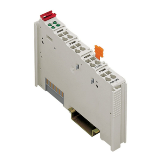
2.1.1.2 View
Visual representation of the module with labeled connections and status LEDs.
2.1.1.3 Description
Explains module function, output channels, wiring, protection, and electrical isolation.
2.1.1.4 Display Elements
Details the function of each status LED (A, B, C, D) corresponding to output channels.
2.1.1.5 Schematic Diagram
Presents the electrical schematic diagram of the 750-504 module, showing components and connections.
2.1.1.6 Technical Data
Lists detailed technical specifications, standards, and approvals for the 750-504 module.
2.1.1.7 Process Image
Defines the output bits (B3-B0) and their mapping to digital output channels (DO 4-DO 1).
Table of Contents
Print
Rename the bookmark
Delete bookmark?
Delete from my manuals?
Login
Sign In
OR
Sign in with Facebook
Sign in with Google
Upload manual
Upload from disk
Upload from URL
Need help?
Do you have a question about the 750-504 and is the answer not in the manual?
Questions and answers