Table of Contents
Advertisement
Quick Links
ASSEMBLY/PRE-RIDE INSPECTION
For questions about these Assembly Instructions, call Coleman
Powersports toll free 888-405-8725
WARNING
!
Never attempt to start this Mini Bike without reading and
understanding the Owner's/Operator's manual. The Owner's/
Operator's manual provides information on safety, parts,
functions, pre-ride inspection, starting and maintenance.
INSTRUCTIONS
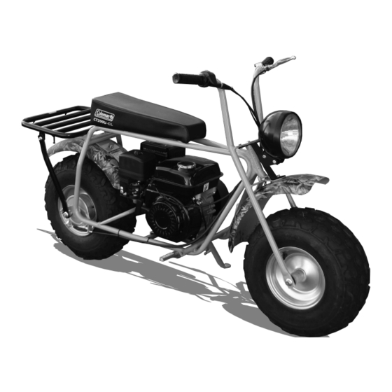
CT200U -C L
CAUTION
This mini bike was
shipped without engine
oil. Always fill with with
the correct amount and
grade of engine oil as
listed in the owner's
manual.
060718
Advertisement
Table of Contents

Subscribe to Our Youtube Channel
Related Manuals for Coleman CT200U-CL


Summary of Contents for Coleman CT200U-CL
- Page 1 For questions about these Assembly Instructions, call Coleman Powersports toll free 888-405-8725 WARNING Never attempt to start this Mini Bike without reading and understanding the Owner’s/Operator’s manual. The Owner’s/ Operator’s manual provides information on safety, parts,...
-
Page 2: Removal From Crate
REMOVAL FROM CRATE 10mm Steering Bolt 10mm Lock Nut 10mm Small Washer Owner’s/Operator’s Manual 10mm Large Washers Front Fork Assembly Hardware Tool Kit Zip Ties Headlight bracket Clutch Cover Front Fender 8mm Nuts 8mm x 20mm Bolts 8mm Large Washers Front fender and headlight Front wheel bracket... -
Page 3: Front Fork Installation
FRONT FORK INSTALLATION 10mm Steering Bolt 10mm Large Washers 10mm Small Washer 10mm Lock Nut Small Washer Steering Bolt 1. Install front Fork Assembly by inserting the 10mm steering bolt Top Bracket through the assembly in the following order: Top bracket, Small 10mm Washer, Steering Neck, Large 10mm Washer, Bottom Bracket, Large 10mm Washer, Lock Nut... - Page 4 HEADLIGHT BRACKET ASSEMBLY Light M 8 x 50 Bolts M 8 R ubber M 8 N uts G rommets Light Headlight 1. Install front l ight onto bracket using M8 X 50 bolts , M8 rubber grommets and M8 nuts. Note: The rubber gromets fit between the light and the light bracket...
- Page 5 FRONT HEADLIGHT AND FENDER INSTALLATION 8mm x 20mm Bolts Large 8mm Washers 8mm Nuts 8mm x 20mm Bolts and M8 Nuts 1. Attach top of light bracket and to top Steering Column Assembly using 8mm x 20mm bolts, and M8 nuts 2.
-
Page 6: Front Wheel Installation
FRONT WHEEL INSTALLATION 14mm Axle bolt 1ea. 14mm washers 2ea. 14mm lock nut 1ea. Arrow faces forward 1. Orient the front tire so the arrow on the tire faces forward. 2. Insert Axle bolt with the 14mm washers between the forks and wheel assembly on each side. - Page 7 SECURE WIRES AND CABLES INSTALL CLUTCH COVER 1. Make sure the On/Off Switch wire, Throttle cable and Brake Zip Ties cable are not kinked and have free movement when the handle bars are turned from left to right. 2. Secure wires and cables to frame using the Zip ties provided.
-
Page 8: Oil And Fuel
OIL AND FUEL Engine Oil Mini bike may have oil in it when shipped from the factory. However, it is a good idea to drain this oil and replace with new SAE 10W-30 Motor Oil. Changing the engine oil 1. Remove the oil fill plug (1) 2. -
Page 9: Tire Pressure
TIRE PRESSURE Tires 1. Check tire pressure. Incorrect tire pressure can affect the handling, rider comfort, steering, tire life and traction. Always check the tire pres- sure before each ride. Tire pressure Front tires: 10psi Rear tires: 10psi Chain tension Check the tension of the chain , The chain (1) tension should be 1/2 - 3/4 in. -
Page 10: Brake Adjustment
BRAKE ADJUSTMENT Brakes 2.0 - 4.0mm Brake Lever Adjustment (0.08 - 0.16 in) The front left brake lever (1) should have 2.0 - 4.0mm (0.08 - 0.16) of free play. To adjust brake lever free play: 1. Loosen the jam nut (2) on the brake cable. -
Page 11: Throttle Cable Adjustment
THROTTLE ADJUSTMENT Throttle Cable adjustment It is important that the throttle grip have a certain amount of free play . The hand grip throttle free play (2) should .078 - .24 in be .078 - .24 in (2-6 mm) (2-6 mm) To adjust freeplay 1. -
Page 12: Pre-Ride Inspection
PRE-RIDE INSPECTION Inspecting and checking the condition of the Mini Bike before each ride is important. Following WHAT TO CHECK FOR the pre-ride check list will help CHECK insure there are no problems which Steering • Smoothness could result in injury or becoming •... -
Page 13: Starting Engine
STARTING ENGINE STARTING ENGINE To start the engine 1. Place the fuel valve (1) to the “ON” (right) position 2.. If engine is cold, place the choke lever (2) to the “ON” (left) position. 3. Place the ON/OFF switch (3), located on the handlebars, to the (on)position. - Page 14 WARNING Never attempt to start this Mini Bike without reading and understanding the Owner’s/Operator’s manual. The Owner’s/ Operator’s manual provides information on safety, parts, functions, pre-ride inspection, starting and maintenance. 1775 E. Universtiy Dr. Tempe, AZ. 85281 PHONE: Toll Free 888-405-8725 colemanpowered.com...
Need help?
Do you have a question about the CT200U-CL and is the answer not in the manual?
Questions and answers