Table of Contents
Advertisement
Quick Links
Advertisement
Table of Contents

Related Manuals for elco THISION EVO WH Series


Summary of Contents for elco THISION EVO WH Series
- Page 1 Operation and Installation manual THISION EVO WH PAG THEWH01 08/2016...
-
Page 3: Table Of Contents
Contents Contents ..............General regulations ........Application ..........Norms and regulations ......Safety Provisions ........Construction Layout of water heater ....... Operating principle ........Thision WH principle ......... Technical data ..............Water heater Installation ......Connecting the water heater ....Unvented Applications ...... -
Page 5: General Regulations
Safety General regulations Application Norms and regulations General regulations The THISION L boiler is CE approved EN 61000-3-2 (2000) This documentation contains important and applies to the following Euro- Electromagnetic compatibility (EMC) - pean standards: information, which is a base for safe Part 3-2: Limits - Limits for harmonic and reliable installation, commissioning 92 / 42 / EEC... -
Page 6: Safety Provisions
Safety Provisions Conditions It is a statutory requirement that all gas appliances are installed in accordance with the manufactures instructions and all current regulations in force, all instructions should be fully read before installing or using the appliance. All installations should be carried out by competent persons as described in the Gas Safety (Installation & Use) Regulations. -
Page 7: Layout Of Water Heater
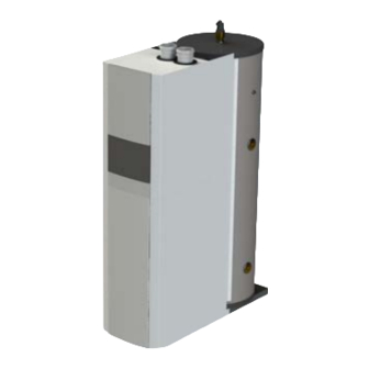
Construc on Layout of the boiler Opera ng principle Layout of boiler The THISION L EVO boiler consists of the following main components: 1. Casing 2. Access door to control panel 3. Flue gas connec on (+ test point) 4. Air intake connec on (+ test point) 5. - Page 8 Thision WH The Thision EVO WH is a standalone DHW charging system that The Thision EVO WH has been designed for ease of consists of a buffer tank, plate heatexchanger and a boiler. installation. For the unit to provide DHW a minimum of the following is required to be installed from the system to the unit: The System is suitable for use in any building with 1.
- Page 9 Technical data Nominal heat output at 80-60ºC max/min 65.5/15.6 111.9/22.5 Nominal heat input Hi max/min 66.8/16.0 114.3/22.9 Efficiency at 80/60ºC 97.4 97.9 Standstill losses 81.0 92.7 Max. condensate flow Gas consumption G20 max/min (10,9 kWh/m 6.1/1.5 10.5/2.1 Gas consumption LPG. max/min (12,8 kWh/kg) kg/h 5.2/1.3 8.9/1.8...
-
Page 10: Technical Data
Technical data THISION EVO THISION EVO DHW Performance Data 10 min peak output at 60ºC (250L storage) 2163 1st hour continous output at 60ºC (250L storage) 1372 10 min peak output at 60ºC (500L storage) 1st hour continous output at 60ºC (500L storage) 2413 1622 Continuous operation at 60ºC... - Page 11 Technical data DHW Flow Cable Gland Cable Gland Secondary Return Condense Waste PRV Drain Inlet Thision EVO WH Thision EVO WH Thision EVO WH Thision EVO WH Dimensions 250 - 120 500- 120 250 - 70 500 - 70 1258 1433 1336 1506...
-
Page 12: Water Heater Installation
Installation Water heater installation Connecting the water heater 300mm Water heater installation The boiler should be positioned in a frost-proof boiler room. If the boiler room is on the roof, the boiler itself may 1000mm 200mm never be the highest point of the instal- lation. - Page 13 Installation Connecting the water heater Flue gas connection (7) Regulations for the construction of flue gas systems are very different for each country. It should be ensured that all national regulations with regard to flue gas systems are respected. Connect the flue gas system to the flue gas connection (7) of the water heater, use flue gas systems with seamless connections only.
-
Page 14: Unvented Applications
Unvented Applications The Thision WH can be fed directly from the mains supply to the property without the need for seperate feed cisterns or vent pipes. It is supplied complete with all its necessary inlet and safety controls, and thermal cut out. Schematic installation details for unvented applications T&P RELIEF PRESSURE REGULATING VALVE... - Page 15 Unvented Applications Worked example of discharge pipe sizing. The example below is for a G1/2 temperature relief valve with a discharge pipe (D2) having 4 No. elbows and length of 7m from the tundish to the point of discharge. From Table 1: Maximum resistance allowed for a straight lenght of 22mm copper discharge pipe (D2) from a G1/2 temperature relief valve is 9.0m.
- Page 16 Cylinder Controls Electrical Connections...
-
Page 17: Commissioning Water And Hydraulic System
Commissioning Water and hydraulic system Commissioning of the water heater should This chapter explains the commissioning be carried out by authorised personnel only. of the water heater with the standard Failure to respect this condition makes the water heater controller. When an additio- guarantee void. -
Page 18: Gas Supply
Commissioning Gas supply Condensate connec on Flue and air intake connec ons Gas supply Check the gas supply connec on to the boiler for soundness before start- ing the boiler! Purge any air between the gas valve and the gas line. This can be done at the test point (1) at the gas pressure switch. -
Page 19: Prepare Water Heater For First Startup
Commissioning Prepare water heater for first startup Preparation for first startup Legend: On/off switch Open the gas supply; Return (ESC) Enable the power supply to the boiler; Room temperature control Confirmation (OK) Switch on the boiler with the on/off Manual mode switch (1);... - Page 20 Commissioning Combus on analysis Combus on se ngs Combus on check at full load Start the boiler in controller stop mode and go to 50% load. Now the boiler operates at 50% load. Allow the boiler to stabilise the combus on for 3 minutes.
-
Page 21: Check Functionality Of Safety Devices
Commissioning Check func onality of safety devices Gas ghtness check Water heater shut down Check func onality of safety devices Gas ghtness check All safety devices must be checked Check the gas ghtness of all sealed for correct opera on/func oning connec ons with approved... -
Page 22: Lockouts
Lockouts In case of a lockout, a warning symbol ( ) and a flashing error code appears on the display. The cause of a fault should first be determined and eliminated before the boiler is being reset. The table below shows all possible lockouts with indication of possible cause. - Page 23 Lockouts Error Description of error code Internal error Parameterization error Unit manually locked Fan error LP error, does not close Error heating circuit flow switch LP error, does not open Alarm contact H1 or H4 active Alarm contact H2 (EM1, EM2 or EM3) or H5 active Alarm contact H6 active Alarm contact H3 or H7 active Limit thermostat heating circuit 1...
- Page 24 Lockouts Error Description of error code Buffer return valve Y15 not available Buffer address sensor Primary controller / system pump address error Pressureless header address error Common flow sensor B10 not available Flow temperature 3 (heating circuit 3) supervision Limit thermostat heating circuit 3 Extension module 3 error (collective error) Buffer return valve Y15 not available Puffer address sensor...
-
Page 25: Maintenance Checklist
Maintenance Checklist Replacing the electrodes Maintenance of the boiler should be Replacing the electrodes carried out by authorized personnel The electrodes are posi oned on the only. top side of the boiler. Replace the igni on electrode (1) and ionisa on In order to ensure con nued good electrode (2) as shown in the and safe opera on of the boiler, it... -
Page 26: Cleaning The Condensate Receptacle
Maintenance Cleaning the condensate receptacle Cleaning and refi lling the syphon Inspec on of combus on chamber Cleaning the condensate receptacle • Disconnect the plug of the fl uegas temperature sensor (1); • Remove the condensate receptacle (2); • Clean the receptacle; •... -
Page 27: Water Pressure And Quality
Maintenance Water pressure and quality Combustion analysis Gas tightness check Check if the water pressure and quality Check the combustion at full load and Check the tightness of all sealed con- meet the requirements. Consult the minumum load, correct the settings if nections with an approved soap or chapter “commissioning: water and necessary. -
Page 28: Maintenance Protocol
Maintenance Maintenance Protocol Maintenance Protocol THISION EVO WH Project e l i l a i y t i System ] - [ d º ] l / Water ∆ l l u º [ Water ∆p boiler ] - [ Safety devices º... -
Page 29: Commissionign Protocol
Commissioning Commissioning protocol Commissioning Protocol THISION EVO WH Project e l i l a i y t i System bar] Installati- Roof top ] - [ d º ] l / .. - Page 30 Service: ELCO UK. 3 Juniper West Fenton Way Southfields Business Park Basildon, Essex, SS15 6SJ Tel 01268 546700...
Need help?
Do you have a question about the THISION EVO WH Series and is the answer not in the manual?
Questions and answers