Table of Contents

Related Manuals for BUSCH COBRA ATEX


Summary of Contents for BUSCH COBRA ATEX
- Page 1 Instruction Manual COBRA ATEX Dry Screw Vacuum Pumps NC 2000 B VR (Vapour Recovery) Ateliers Busch S.A. Zone industrielle, 2906 Chevenez Switzerland 0870557375/A0002_en / Original instructions / Modifications reserved 25/09/2018...
-
Page 2: Table Of Contents
Table of Contents Table of Contents 1 Safety........................... 4 2 Product Description ..................... 5 2.1 Operating Principle....................6 2.2 Application ......................6 2.3 Standard Features....................6 2.3.1 Cooling......................6 2.3.2 Sealing Systems ..................7 2.4 Standard Accessories .................... 7 2.4.1 Resistance Thermometer................7 2.4.2 Vibration Analysis System ................7 2.4.3 Level Switch....................7 2.4.4 Pressure Transmitter ..................7... - Page 3 Table of Contents 7.4.1 Procedure A....................29 7.4.2 Procedure C....................29 7.4.3 Procedure D....................29 7.4.4 Procedure F ....................29 8 Overhaul........................30 9 Decommissioning ......................30 9.1 Dismantling and Disposal..................30 10 Spare Parts ........................31 11 Troubleshooting......................31 12 Technical Data ......................33 13 Oil ..........................
-
Page 4: Safety
Safety Prior to handling the machine, this instruction manual should be read and understood. If anything needs to be clarified, please contact your Busch representative. Read this manual carefully before use and keep for future reference. This instruction manual remains valid as long as the customer does not change anything on the product. -
Page 5: Product Description
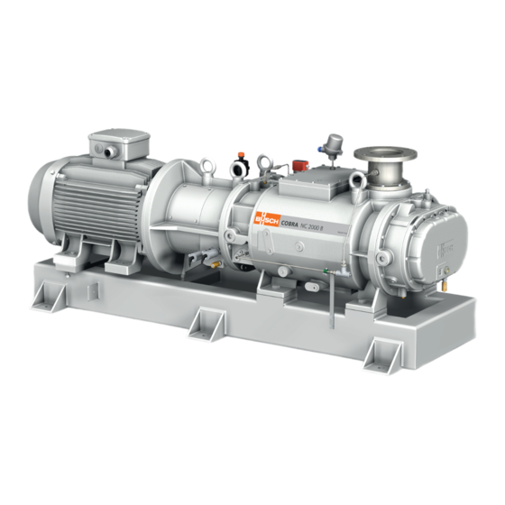
Product Description | 2 Product Description LS-/0201 LS+/0202 PSA+/0301 TSA+/0101 SA+/0701 TSA+/0102 Cooling liquid drain plug Cooling liquid inlet connection Cooling liquid outlet connection Eye bolt Earth connection (machine) Suction connection Injection point Level switch Magnetic plug Motor terminal box Nameplate Oil drain valve Oil fill plug... -
Page 6: Operating Principle
2G IIB T4 X Outside (o) 2G IIB T4 X In case Busch delivered the machine without motor and coupling, the following must be observed: • In regards to its explosive atmosphere protection class, the motor and the coup- ling must have at least the same ATEX classification as the machine for the outside area “Outside (o)”. -
Page 7: Sealing Systems
Product Description | 2 2.3.2 Sealing Systems Sealing systems prevent the process gas going to the bearings chambers. The machine is equipped with oil lubricated single mechanical seal with labyrinth seal on the motor side and oil lubricated single mechanical seal with lip seal on the suction side. 2.4 Standard Accessories 2.4.1 Resistance Thermometer The resistance thermometer monitors the exhaust gas temperature. -
Page 8: Explanation Of Atex Classification
• Make sure that the recommendations described in this manual correspond to the ATEX marking written on the nameplate (NP). • If anything needs to be clarified, please contact your Busch representative. The safety concept is based on the prevention of sparks and excessive temperatures by means of various accessories. -
Page 9: List Of Mandatory Atex Accessories
Product Description | 2 2.7.1 List of Mandatory ATEX Accessories The following list indicates the mandatory accessories according to the ATEX classifica- tion of the machine. (i) II 2G IIB T4 X TSA+ PSA+ ATEX ATEX (o) II 2G IIB T4 X /0102 /0301 /0701... -
Page 10: Transport
3 | Transport Transport WARNING Suspended load. Risk of severe injury! • Do not walk, stand or work under suspended loads. NOTICE In case the machine is already filled with oil. Tilting a machine that is already filled with oil can cause large quantities of oil to in- gress into the cylinder. -
Page 11: Storage
• Make sure that the cooling liquid complies with the requirements, see Cooling Liquid Connection [► 13]. If the machine is installed at an altitude greater than 1000 meters above sea level: • Contact your Busch representative, the motor should be derated or the ambient temperature limited. 0870557375_NC2000B_VR_Ex_A0002_IM_en... -
Page 12: Connecting Lines / Pipes
– DN150 PN16, EN 1092-1 – ANSI 150, 6” (optional) If the machine is used as part of a vacuum system: • Busch recommends the installation of an isolation valve in order to prevent the machine from turning backwards. 12 / 36... -
Page 13: Discharge Connection
Installation | 5 5.2.2 Discharge Connection Connection size: – DN100 PN16, EN 1092-1 – ANSI 150, 4” (optional) • Make sure that the discharged gas will flow without obstruction. Do not shut off or throttle the discharge line or use it as a pressurised air source. •... -
Page 14: Filling Oil
Risk of premature failure! Loss of efficiency! • Only use an oil type which has previously been approved and recommended by Busch. For oil type and oil capacity see Technical Data [► 33] and Oil [► 33]. Oil filling at the motor side... - Page 15 Last oil change __ / __ / ____ Oil type see nameplate Change interval see instruction manual If there is no sticker (part no. 0565 568 959) on the machine: • Order it from your Busch representative. 0870557375_NC2000B_VR_Ex_A0002_IM_en 15 / 36...
-
Page 16: Fitting The Coupling
• Provide an overload protection according to EN 60204-1 for the motor. • Make sure that the motor of the machine will not be affected by electric or electro- magnetic disturbance from the mains; if necessary seek advice from Busch. • Connect the protective earth conductor. -
Page 17: Wiring Diagram Three-Phase Motor (Pump Drive)
Installation | 5 NOTICE The admissible motor nominal speed exceeds the recommendation. Risk of damage to the machine! • Check the admissible motor nominal speed (n ) on the nameplate of the machine (NP). • Make sure to comply with it. •... -
Page 18: Electrical Connection Of The Monitoring Devices
• Switch any two of the motor phase wires. 5.7 Electrical Connection of the Monitoring Devices NOTE In order to prevent potential nuisance alarms, Busch allows that the control system is configured with a time delay of 2 seconds. NOTE The accessories below are considered as standard. -
Page 19: Wiring Diagram Vibration Sensor
An intrinsic safety barrier must be installed between the vibration sensor and the measur- ing transmitter to prevent any fault voltage in the hazardous area. For example: STAHL 9001/01-280-085-101 The intrinsic safety barrier is not included in the scope of delivery of Ateliers Busch SA. 0870557375_NC2000B_VR_Ex_A0002_IM_en 19 / 36... -
Page 20: Wiring Diagram Level Switch
5 | Installation 5.7.3 Wiring Diagram Level Switch Part no.: 0652 556 531 Supplier reference: Endress&Hauser FTL50/FEL58 Maintenance procedure: Procedure F [► 29] 1 = Brown ; 4 = Black Connector: M12x1, 4-pin 1 = Brown ; 2 = White P&ID position: LS-/0201 & LS+/0202 Electrical data: Ui = 16 VDC ;... - Page 21 Installation | 5 * The quantity of cooling liquid injected should be sufficient to ensure that at no time during the operation of the pump, the maximum exhaust gas outlet temperature is ex- ceeded. 0870557375_NC2000B_VR_Ex_A0002_IM_en 21 / 36...
-
Page 22: Flowchart
5 | Installation 5.9 Flowchart The machine safety depends on the monitoring accessories sequencing according to the following flowchart. Start Oil level is higher than LS-/0201? Oil level is lower than LS+/0202? Machine is running for less than 24 hours? Warning: T <... -
Page 23: Commissioning
Commissioning | 6 Commissioning NOTICE The machine may ship without oil. Operation without oil will ruin the machine in short time! • Prior to commissioning, the machine must be filled with oil, see Filling Oil [► 14]. NOTICE Lubricating a dry running machine (compression chamber). Risk of damage to the machine! •... -
Page 24: Switch Off
7 | Maintenance 6.2 Switch Off • Vent the machine at a pressure between atmospheric pressure and 650 hPa. • Close the cooling liquid injection. • Let the machine run for 1 minute. • Stop the machine • Close the cooling liquid supply. 6.3 Restart Procedure Prior to restart the system, ascertain the reason for the emergency stop. -
Page 25: Maintenance Schedule
Failing to properly maintain the machine. Risk of premature failure! Loss of efficiency! • Respect the maintenance intervals or ask your Busch representative for service. • Shut down the machine and lock against inadvertent start up. • Turn off the cooling liquid supply. -
Page 26: Oil Level Inspection
NOTICE Use of an inappropriate oil. Risk of premature failure! Loss of efficiency! • Only use an oil type which has previously been approved and recommended by Busch. Oil draining at the motor side Cleaning cloth Magnetic plug Drain pan... - Page 27 Maintenance | 7 Magnetic plug Oil draining at the suction side Cleaning cloth Magnetic plug Drain pan 0870557375_NC2000B_VR_Ex_A0002_IM_en 27 / 36...
- Page 28 7 | Maintenance For oil type and oil capacity see Technical Data [► 33] and Oil [► 33]. Oil filling at the motor side Check oil level Oil filling at the suction side Check oil level When the oil filling is achieved: •...
-
Page 29: Calibration Procedure Of The Electrical Devices
Change interval see instruction manual If there is no sticker (part no. 0565 568 959) on the machine: • Order it from your Busch representative. 7.4 Calibration Procedure of the Electrical Devices 7.4.1 Procedure A • Remove the resistance thermometer from the machine. -
Page 30: Overhaul
• Decontaminate the machine as well as possible and state the contamination status in a ‘Declaration of Contamination’. Busch will only accept machines that come with a completely filled in and legally binding signed ‘Declaration of Contamination’. (Form downloadable from www.buschvacuum.com) Decommissioning •... -
Page 31: Spare Parts
• The exclusive use of Busch genuine spare parts and consumables is recommended for the proper function of the machine and for granting of warranty. There is no standard spare parts kits available for this product, if you require Busch gen- uine parts: •... - Page 32 Oil Change [► 26]. The machine runs too hot. • See problem "The ma- chine runs too hot". For the solution of problems not mentioned in the troubleshooting chart contact your Busch representative. 32 / 36 0870557375_NC2000B_VR_Ex_A0002_IM_en...
-
Page 33: Technical Data
Oil capacity - motor side Oil capacity - suction side Weight approx. 2000 Please contact your Busch representative if the operating conditions fall outside of the recommended parameters as outlined. 13 Oil Shell Tellus S2 M Shell Tellus S2 V 68 TOTAL AZOLLA ZS... -
Page 34: Eu Declaration Of Conformity
This Declaration of Conformity and the CE-mark affixed to the nameplate are valid for the machine within the Busch scope of delivery. This Declaration of Conformity is issued under the sole responsibility of the manufacturer. When this machine is integrated into a superordinate machinery the manufacturer of the superordinate machinery (this can be the operating company, too) must conduct the conformity assessment process for the superordinate machine or plant, issue the Declaration of Conformity for it and affix the CE-mark. - Page 35 Note...
- Page 36 Czech Republic Netherlands Turkey www.buschvacuum.cz www.busch.nl www.buschvacuum.com Denmark New Zealand United Arab Emirates www.busch.dk www.busch.com.au www.busch.ae Finland Norway United Kingdom www.busch.fi www.busch.no www.busch.co.uk France Peru www.busch.fr www.busch.com.pe www.buschusa.com Germany Poland www.busch.de www.busch.com.pl www.buschvacuum.com 0870557375/A0002_en / © Ateliers Busch S.A.
Need help?
Do you have a question about the COBRA ATEX and is the answer not in the manual?
Questions and answers