Table of Contents

Related Manuals for BUSCH COBRA NF 0750 A


Summary of Contents for BUSCH COBRA NF 0750 A
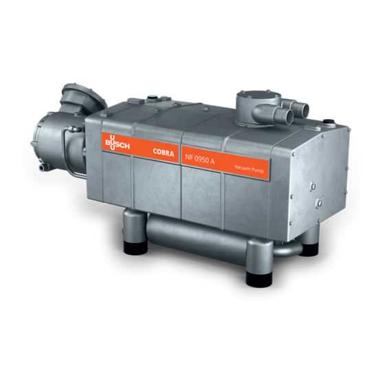
- Page 1 Instruction Manual COBRA Dry Screw Vacuum Pumps NF 0750 A, NF 0950 A Water-Cooled Version Ateliers Busch S.A. Zone industrielle, 2906 Chevenez Switzerland 0870232965/-0001_en / Original instructions / Modifications reserved 10/05/2021...
-
Page 2: Table Of Contents
Table of Contents Table of Contents 1 Safety ............................4 2 Product Description ........................5 2.1 Operating Principle ......................6 2.2 Application........................6 2.3 Start Controls ........................7 2.4 Standard Features ......................7 2.4.1 Water Cooling ....................... 7 2.4.2 Temperature Switch ....................7 2.4.3 Sealing Systems ..................... - Page 3 Table of Contents 13 Oil ............................33 14 EU Declaration of Conformity....................34 0870232965_NF0750A_NF0950A_WCV_-0001_IM_en...
-
Page 4: Safety
Safety Prior to handling the machine, this instruction manual should be read and understood. If anything needs to be clarified, please contact your Busch representative. Read this manual carefully before use and keep for future reference. This instruction manual remains valid as long as the customer does not change anything on the product. -
Page 5: Product Description
Product Description | 2 Product Description IN, IS Cooling water drain plug Cooling water inlet Cooling water outlet Eye bolt Gas ballast valve Suction connection Inlet screen Magnetic plug Motor terminal box Nameplate Oil drain plug Oil fill plug Oil sight glass Discharge connection Plug for manual rotation of rotors Silencer... -
Page 6: Operating Principle
Busch for oxygen applications (see Filling Oil [► 14]). • Follow the additional commissioning instructions (see Commis- sioning [► 18]). • Follow the additional maintenance instructions (see Maintenance [► 22] and Oil Change [► 27]). • Only use Busch genuine spare parts (see Spare Parts [► 31]). 6 / 36 0870232965_NF0750A_NF0950A_WCV_-0001_IM_en... -
Page 7: Start Controls
- Steel - Stainless Steel - Aluminium - Fluoroelastomer (FKM/FPM) • In doubt, please contact your Busch representative. 2.3 Start Controls The machine comes without start controls. The control of the machine is to be provided in the course of installation. -
Page 8: Optional Accessories
2 | Product Description WARNING The barrier gas system is obligatory for the suction of process gas with > 21% vol. oxy- gen. 2.5 Optional Accessories 2.5.1 Gas Ballast Valve The gas ballast valve mixes the process gas with a limited quantity of ambient air to counteract the condensation of vapour inside the machine. -
Page 9: Transport
Transport | 3 Transport WARNING Suspended load. Risk of severe injury! • Do not walk, stand or work under suspended loads. WARNING Lifting the machine using the motor eye bolt. Risk of severe injury! • Do not lift the machine using the eye bolt fitted to the motor. Only lift the machine as shown. -
Page 10: Storage
4 | Storage Storage • Seal all apertures with adhesive tape or reuse provided caps. If the machine is to be stored for more than 3 months: • Wrap the machine in a corrosion inhibiting film. • Store the machine indoors, dry, dust free and if possible in original packaging preferably at temperatures between 5 ... -
Page 11: Connecting Lines / Pipes
• Make sure that the line size of the connection lines over the entire length is at least as large as the connections of the machine. In case of long connection lines it is advisable to use larger line sizes in order to avoid a loss of efficiency. Seek advice from your Busch representative. 5.2.1 Suction Connection WARNING Unprotected suction connection. -
Page 12: Discharge Connection
5 | Installation 5.2.2 Discharge Connection Connection size(s): At the silencer (SI) discharge connection: – G3, horizontal • Make sure that the discharged gas will flow without obstruction. Do not shut off or throttle the discharge line or use it as a pressurised air source. •... -
Page 13: Barrier Gas System Connection (Optional)
Installation | 5 • To reduce the maintenance effort and ensure a long product lifetime we recommend the following cooling water quality: Hardness mg/l (ppm) < 90 Properties Clean & clear PH value 7 ... 8 Particle size µm < 200 Chloride mg/l <... -
Page 14: Filling Oil
Use of an inappropriate oil. Risk of premature failure! Loss of efficiency! • Only use an oil type which has previously been approved and recommended by Busch. WARNING Use of an inappropriate oil. Process gas with > 21% vol. oxygen, risk of fire! •... - Page 15 Installation | 5 For oil type and oil capacity see Technical Data [► 33] and Oil [► 33]. Oil filling at the motor side Check oil level Oil filling at the inlet side Check oil level When the oil filling is achieved: •...
-
Page 16: Electrical Connection
• Provide an overload protection according to EN 60204-1 for the motor. • Make sure that the motor of the machine will not be affected by electric or electro- magnetic disturbance from the mains; if necessary seek advice from Busch. • Connect the protective earth conductor. -
Page 17: Wiring Diagram Three-Phase Motor (Pump Drive)
Installation | 5 NOTICE Incorrect connection. Risk of damage to the motor! • The wiring diagrams given below are typical. Check the inside of the terminal box for motor connection instructions/diagrams. 5.4.1 Wiring Diagram Three-Phase Motor (Pump Drive) • Make sure that you select the proper frequency drive according to the motor specific- ations. -
Page 18: Electrical Connection Of The Monitoring Devices
– 1 x M16 x 1.5 5.5 Electrical Connection of the Monitoring Devices NOTE In order to prevent potential nuisance alarms, Busch recommends that the control system is configured with a time delay of at least 20 seconds. 5.5.1 Wiring Diagram Temperature Switch Part no.: 0651 563 762... - Page 19 Commissioning | 6 NOTICE The machine can be shipped without oil. Operation without oil will ruin the machine in short time! • Prior to commissioning, the machine must be filled with oil, see Filling Oil [► 14]. NOTICE The machine can be shipped without cooling liquid. Operation without cooling liquid will ruin the machine in short time! •...
-
Page 20: Start Procedure
6 | Commissioning 6.1 Start Procedure START Procedure Open barrier gas supply - visual confirmation Open cooling water supply Temperature switch closed ? Machine in operation ? Start the machine Ramp up time: 150 seconds Emergency STOP button Minimum speed: 20Hz activated ? Maximum speed: 60Hz (NF 0750 A) -
Page 21: Shutdown Procedure
Commissioning | 6 6.2 Shutdown Procedure SHUTDOWN Procedure Isolate Process from pump; run pump for 15 minutes Stop the machine Ramp down time: 30 seconds Close barrier gas supply Close cooling water supply Machine off 0870232965_NF0750A_NF0950A_WCV_-0001_IM_en 21 / 36... -
Page 22: Maintenance
• The machine must be removed from service and cleaned by specialists (contact your Busch representative). WARNING Use of non-Busch genuine spare parts. Risk of fire! • Only use Busch spare parts approved by Busch and suitable for oxygen application. WARNING Machines contaminated with hazardous material. Risk of poisoning! Risk of infection! If the machine is contaminated with hazardous material: •... - Page 23 Risk of injuries! Risk of premature failure and loss of efficiency! • Respect the maintenance intervals or ask your Busch representative for service. • Shut down the machine and lock against inadvertent start up. • Turn off the water supply.
-
Page 24: Maintenance Schedule
Monthly • Check the oil level, see Oil Level Inspection [► 24]. • Check the machine for oil leaks - in case of leaks have the machine repaired (contact Busch). Yearly • Carry out a visual inspection and clean the machine from dust and dirt. -
Page 25: Cleaning The Inlet Screen
Maintenance | 7 7.3 Cleaning the Inlet Screen 7.3.1 Cleaning the Inlet Screen with Vertical Flange G3 or DN100 hex key Compressed air 7.3.2 Cleaning the Inlet Screen with Horizontal Flange G3 Compressed air 0870232965_NF0750A_NF0950A_WCV_-0001_IM_en 25 / 36... -
Page 26: Cleaning The Inlet Screen With Double Flange G2
7 | Maintenance 7.3.3 Cleaning the Inlet Screen with Double Flange G2 Compressed air Max. admissible torque : 12 Nm 7.4 Cleaning the Gas Ballast Filter (Optional) 36 mm wrench Compressed air 26 / 36 0870232965_NF0750A_NF0950A_WCV_-0001_IM_en... -
Page 27: Oil Change
NOTICE Use of an inappropriate oil. Risk of premature failure! Loss of efficiency! • Only use an oil type which has previously been approved and recommended by Busch. Oil draining at the motor side Cleaning cloth Magnetic plug Drain pan... - Page 28 7 | Maintenance Oil draining at the suction side Cleaning cloth Magnetic plug Drain pan For oil type and oil capacity see Technical Data [► 33] and Oil [► 33]. Oil filling at the motor side Check oil level 28 / 36 0870232965_NF0750A_NF0950A_WCV_-0001_IM_en...
- Page 29 Change interval see instruction manual If there is no sticker (part no. 0565 568 959) on the machine: • Order it from your Busch representative. WARNING Use of an inappropriate oil. Process gas with > 21% vol. oxygen, risk of fire! •...
-
Page 30: Overhaul
• Decontaminate the machine as much as possible and state the contamination status in a ‘Declaration of Contamination’. Busch will only accept machines that come with a completely filled in and legally binding signed ‘Declaration of Contamination’ (form downloadable from www.buschvacuum.com). -
Page 31: Spare Parts
• The exclusive use of Busch genuine spare parts and consumables is recommended for the correct functioning of the machine and to validate the warranty. There is no standard spare parts kits available for this product, if you require Busch gen- uine parts: •... - Page 32 Busch). Solid foreign matter has • Remove the solid foreign entered the machine. matter or repair the ma- chine (contact Busch). • Check the inlet screen (IS) at the suction connection. The temperature switch (TS) • Let the machine cool reached the switch point.
-
Page 33: Technical Data
Technical Data | 12 12 Technical Data NF 0750 A NF 0950 A Pumping speed (with inlet G3 or ISO m³/h DN100)* ACFM Ultimate pressure (without gas ballast) hPa (mbar) abs. ≤0.05 ≤0.01 Torr ≤0.0375 ≤0.0075 Ultimate pressure (with gas ballast) hPa (mbar) abs. - Page 34 This Declaration of Conformity and the CE-mark affixed to the nameplate are valid for the machine within the Busch scope of delivery. This Declaration of Conformity is issued under the sole responsibility of the manufacturer. When this machine is integrated into a superordinate machinery the manufacturer of the superordinate machinery (this can be the operating company, too) must conduct the conformity assessment process for the superordinate machine or plant, issue the Declaration of Conformity for it and affix the CE-mark.
- Page 35 Note...
- Page 36 Chile Israel Portugal United Arab Emirates info@busch.cl service_sales@busch.co.il busch@busch.pt sales@busch.ae China Italy Romania United Kingdom info@busch-china.com info@busch.it office@buschromania.ro sales@busch.co.uk Colombia Japan Russia info@buschvacuum.co info@busch.co.jp info@busch.ru info@buschusa.com Czech Republic Korea Singapore info@buschvacuum.cz busch@busch.co.kr sales@busch.com.sg www.buschvacuum.com 0870232965/-0001_en / © Ateliers Busch S.A.
Need help?
Do you have a question about the COBRA NF 0750 A and is the answer not in the manual?
Questions and answers