Advertisement
Quick Links
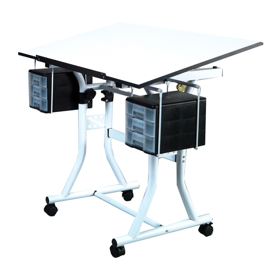
U-DS90W Creation Station
[8] M6 x 13mm [A]
[8] M4.2 x 16mm [E]
[2] Small Wood Screws [I]
[1] Small Wrench [M]
IMPORTANT
If you have difficulty assembling your U-DS90W
Creation Station or need customer service
assistance. Please call:
Martin Universal Design, Inc.
Customer Service Hot Line at
1-313-895-0700.
If you need additional parts,
it is not necessary to contact your dealer,
our Customer Service Rep. will forward them
to you immediately.
Assembly Instructions
Contents of Hardware Pack:
[4] Nuts [B]
[8] M4.2 x 12mm [F]
[2] Locking Castors [J]
[1] Allen Wrench [N]
4444 Lawton Avenue, Detroit, MI 48208 USA • Tel:(313)895-0700/Fax:(313)895-0709
Email: Custservmud@aol.com • visit us at www.MartinUniversalDesign.com
[4] 1/4" x 35mm [C]
[4] Collars [G]
[2] Castors [K]
List of Hardware:
Qty
Part Description
[8]
M6 x 35mm
[4]
Nuts
[4]
1/4" x 35mm
[8]
1/4" x 2-1/2"
[8]
M4.2 x 16mm
[8]
M4.2 x 12mm
[4]
Collars
[4]
Male Knobs
[2]
Small Wood Screws
[2]
Locking Castors
[2]
Castors
[1]
Large Wrench
[1]
Small Wrench
[1]
Allen Wrench
[8] 1/4" x 2-1/2" [D]
[4] Male Knobs [H]
[1] Large Wrench [L]
Part Number
[A]
[B]
[C]
[D]
[E]
[F]
[G]
[H]
[I]
[J]
[K]
[L]
[M]
[N]
Advertisement

Related Manuals for Martin Universal Design U-DS90W


Summary of Contents for Martin Universal Design U-DS90W
- Page 1 [1] Small Wrench [M] [1] Allen Wrench [N] M4.2 x 16mm M4.2 x 12mm IMPORTANT Collars If you have difficulty assembling your U-DS90W Creation Station or need customer service Male Knobs assistance. Please call: Small Wood Screws Martin Universal Design, Inc.
- Page 2 Part Description Part Number IMPORTANT 20” x 40” White Top Lower Base End Unit If you have difficulty assembling your U-DS90W Upper Base End Unit (left) Creation Station or need customer service Upper Base End Unit (right) assistance. Please call: Base Cross Support Bar Martin Universal Design, Inc.
- Page 3 Assembly Instructions: STEP 1] Assembly Base of table STEP 3] Complete Base Assembly Begin by taking the [2] Lower Base End units (part #2 and Take the top portion and the lower portion of the base that attach the foot bar (part # 7) and the Base Cross Support bar was just assembled.
- Page 4 Assembly Instructions: STEP 5] Attach Drawer Units to Base STEP 7] Attach L-Bracket to Base Attach the drawer units to the table base as illustrated below Take the L-Bracket (part #11) and insert the pin that is at- using [4] M4.2 x 16mm screws (part E) for each drawer unit. tached to the L-Bracket into the hole on the inside section of See FIG 5 below.
Need help?
Do you have a question about the U-DS90W and is the answer not in the manual?
Questions and answers