Advertisement
SPLIT TYPE
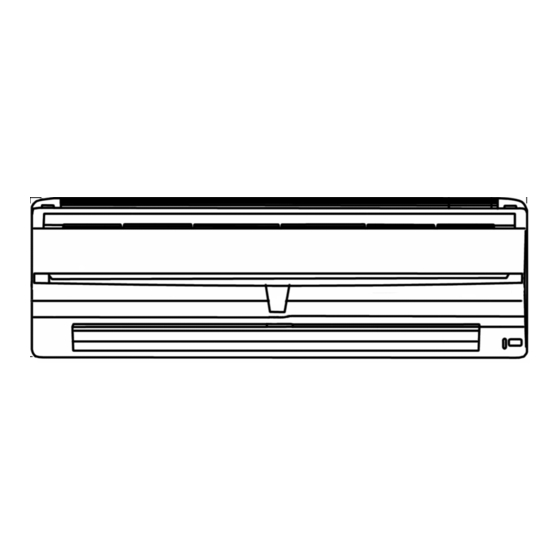
ROOM AIR CONDITIONER
WALL MOUNTED
Models
Indoor unit
ASH7FSBCW
ASH7USBCW
ASH7USBCW AOH7USNC
CONTENTS
SPECIFICATIONS . . . . . . . . . . . . . . . . . . . . . . . . . . . . . . . . . . . . . . . . 1
DIMENSIONS . . . . . . . . . . . . . . . . . . . . . . . . . . . . . . . . . . . . . . . . . . . 2
REFRIGERANT SYSTEM DIAGRAM . . . . . . . . . . . . . . . . . . . . . . . . 3
CIRCUIT DIAGRAM . . . . . . . . . . . . . . . . . . . . . . . . . . . . . . . . . . . . . . 4
INDOOR PRINTED CIRCUIT BOARD CIRCUIT DIAGRAM . . . . .
ERROR DISPLAY . . . . . . . . . . . . . . . . . . . . . . . . . . . . . . . . . . . . . . . .
DISASSEMBLY ILLUSTRATION . . . . . . . . . . . . . . . . . . . . . . . . . . . . 9
PARTS LIST . . . . . . . . . . . . . . . . . . . . . . . . . . . . . . . . . . . . . . . . . . .15
type
Outdoor unit
AOH7FSBC
AOH7USBC
6
8
Advertisement
Table of Contents

Related Manuals for General ASH7FSBCW


Summary of Contents for General ASH7FSBCW
-
Page 1: Table Of Contents
ROOM AIR CONDITIONER WALL MOUNTED type Models Indoor unit Outdoor unit ASH7FSBCW AOH7FSBC ASH7USBCW AOH7USBC ASH7USBCW AOH7USNC CONTENTS SPECIFICATIONS ........1 DIMENSIONS . -
Page 2: Specifications
SPECIFICATIONS TYPE Cooling Cooling and Heat-pump heating INDOOR UNIT ASH7FSBCW ASH7USBCW OUTDOOR UNIT AOH7FSBC AOH7USBC AOH7USNC COOLING CAPACITY (kW) 2.25 2.20 HEATING CAPACITY (kW) ----- 2.30 ELECTRICAL SPECIFICATIONS POWER SOURCE Single-phase 230V 50Hz COOLIING RUNNING CURRENT HEATING ----- COOLIING 0.80 0.83... -
Page 3: Dimensions
DIMENSIONS U nit : m m Models : ASH7FSBCW ASH7USBCW Models : AOH7FSBC AOH7USBC AOH7USNC 2005.02.10... -
Page 4: Refrigerant System Diagram
REFRIGERANT SYSTEM DIAGRAM Models : ASH7FSBCW / AOH7FSBC INDOOR UNIT Evaporator (Flare connection) (Flare connection) [ Connecting pipe ] Gas pipe (9.52 dia.) Liquid pipe (6.35 dia.) (Flare connection) (Flare connection) OUTDOOR UNIT 3-Way valve 2-Way valve (with charging port) -
Page 5: Circuit Diagram
Thermistor (room) CIRCUIT DIAGRAM Thermistor (pipe) Test Models : ASH7FSBCW / AOH7FSBC Step Motor Controller PCB Fan Motor Relay INDOOR UNIT Transformer Terminal OUTDOOR UNIT Terminal BLACK BLACK Compressor WHITE BLUE Overload Relay Fan Motor Capacitor Compressor Fan Motor Capacitor... - Page 6 Thermistor (room) Thermistor (pipe) Models : ASH7USBCW / AOH7USBC Test ASH7USBCW / AOH7USNC Stepping Motor Controller PCB Fan Motor Relay INDOOR UNIT Fan Motor Capacitor Transformer OUTDOOR UNIT Terminal Fan Motor Capacitor Terminal Compressor Compressor Capacitor Overload 4-way Relay Valve Coil 2005.02.10...
-
Page 7: Indoor Pcb Circuit Diagram
INDOOR PCB CIRCUIT DIAGRAM Model : ASH7FSBCW POWER TRANSFORMER EZ-030HSE-T PRIMARY SECONDARY CONTROLLER PCB ASSEMBLY ( MAIN PCB ) EZ-003TWSE-C ( F ) POWER SUPPLY PCB I C 1 EZ-002SWSE-P uPD780024ASGB-X26-8ET R29 10K R30 1.0K <1/10W> MANUAL AUTO PKM13EPY-4000 DTC124EUA <1/10W>... - Page 8 Model : ASH7USBCW POWER TRANSFORMER EZ-030HSE-T CONTROLLER PCB ASSEMBLY (MAIN PCB) EZ-0030AHSE-C (F) POWER SUPPLY PCB I C 1 EZ-002YHSE-P uPD780024ASGB-X25-8ET R29 10K R30 1.0K <1/10W> MANUAL AUTO DTC124EUA W105 W106 PKM13EPY-4000 <1/10W> SWITH R28 10K FAN MOTOR S3P-VH CN101-1 CN7-1 R14 10K <1/10W>...
-
Page 9: Error Display
ERROR DISPLAY Troubleshooting check table Operation lamp : Red lamp Timer lamp : Green lamp Large division indication Small division indication Error contents LED indication Error contents LED indication (2 times) thermistor error (room temp.) Red lamp thermistor error Red lamp Green lamp Green lamp (2 times) -
Page 10: Disassembly Illustration
DISASSEMBLY ILLUSTRATION Model : ASH7FSBCW ASH7USBCW 2005.02.10... - Page 11 Model : ASH7FSBCW 2005.02.10...
- Page 12 Model : ASH7USBCW 2005.02.10...
- Page 13 Model : AOH7USNC 2005.02.10...
- Page 14 Model : AOH7USBC 2005.02.10...
- Page 15 Model : AOH7USNC 2005.02.10...
-
Page 16: Parts List
PARTS LIST INDOOR UNIT Part No. Ref. Ord. Description Q'ty ASH7FSBCW ASH7USBCW Blower Cover 9306462000 9306462000 Capacitor(Fan Motor) 9900133016 9900089061 Front Panel Assy 9312172085 9312172085 Flow Control Panel-Z 9306058043 9306058012 Louver-A 9306055028 9306055028 Filter 9305444014 9305444014 Base 9309755062 9309755062 Casing... - Page 17 OUTDOOR UNIT Part No. Part No. Ref. Ord. Ref. Ord. Description Description Q'ty Q'ty AOH7FSBC AOH7USBC AOH7USNC Emblem-Rear 9308474018 Emblem-Rear 9308474018 9308474018 Cabinet Front Panel, Plastic 9306016012 Cabinet Front Panel, Plastic 9306016012 9306016012 Connector Cover 9306018016 Connector Cover 9306018016 9306018016 Cabinet Rear Panel, Plastic 9306017019 Cabinet Rear Panel, Plastic...
-
Page 18: Standard Accessories
STANDARD ACCESSORIES Part No. Name and Shape ASH7FSBCW ASH7USBCW Wall hook bracket 9304358008 9304358008 Remote control unit 9312058037 9312058020 Battery (penlight) 0600185534 0600185534 Tapping screw ( 4 x 25 ) 0700076046 0700076046 Cloth tape 9308117007 9308117007 Drain pipe (Including drain packing) 9303029015 2005.02.10... - Page 19 0311G2409...
Need help?
Do you have a question about the ASH7FSBCW and is the answer not in the manual?
Questions and answers