Table of Contents
Advertisement
Quick Links
Advertisement
Table of Contents

Related Manuals for Innova CarScan


Summary of Contents for Innova CarScan
-
Page 2: Table Of Contents
Table of Contents SAFETY PRECAUTIONS ..............SAFETY FIRST! SCAN TOOL CONTROLS .......... CONTROLS AND INDICATORS ............DISPLAY FUNCTIONS ............INITIAL ADJUSTMENTS ONBOARD DIAGNOSTICS ........COMPUTER ENGINE CONTROLS ......11 DIAGNOSTIC TROUBLE CODES (DTCs) ............... 14 OBD2 MONITORS USING THE SCAN TOOL CODE RETRIEVAL PROCEDURE ......... -
Page 3: Safety Precautions
Safety Precautions SAFETY FIRST! SAFETY FIRST! This manual describes common test procedures used by experienced service technicians. Many test procedures require precautions to avoid accidents that can result in personal injury, and/or damage to your vehicle or test equipment. Always read your vehicle's service manual and follow its safety precautions before and during any test or service procedure. -
Page 4: Scan Tool Controls
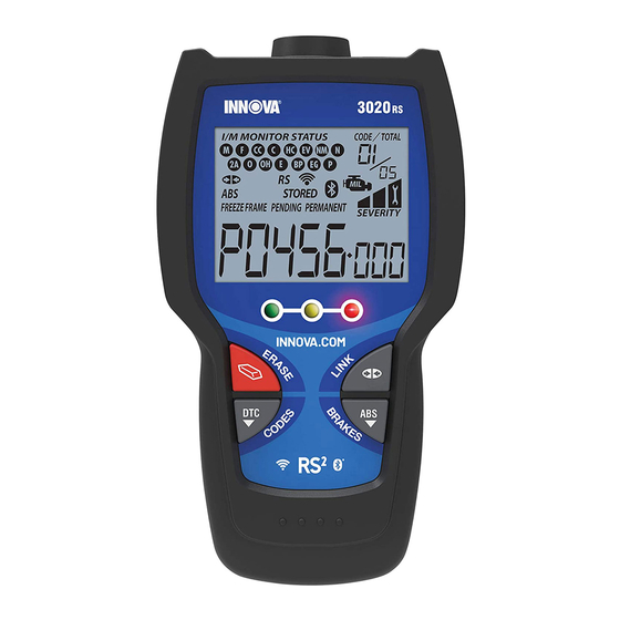
Scan Tool Controls CONTROLS AND INDICATORS CONTROLS AND INDICATORS Figure 1. Controls and Indicators See Figure 1 for the locations of items 1 through 14, below. ERASE button - Erases Diagnostic Trouble Codes (DTCs), and “Freeze Frame” data from your vehicle’s computer, and resets Monitor status. -
Page 5: Display Functions
Scan Tool Controls DISPLAY FUNCTIONS 6. LD button – When pressed while linked to a vehicle, places the Scan Tool in Live Data mode. UP button – When in MENU mode, scrolls UP through the menu options. When LINKED to a vehicle, scrolls UP through the current display screen to display any additional data. - Page 6 Scan Tool Controls DISPLAY FUNCTIONS 1. I/M MONITOR STATUS field - Identifies the I/M Monitor status area. 2. Monitor icons - Indicate which Monitors are supported by the vehicle under test, and whether or not the associated Monitor has run its diagnostic testing (Monitor status).
-
Page 7: Initial Adjustments
Harmful and damaging to essential system components. Bluetooth icon – Indicates communication status with a compatible Innova mobile application (please visit www.innova.com/apps for more information). A solid blue icon indicates an active Bluetooth connection has been established. A solid grey icon indicates Bluetooth is not connected. -
Page 8: Onboard Diagnostics
Onboard Diagnostics COMPUTER ENGINE CONTROLS COMPUTER ENGINE CONTROLS The Introduction of Electronic Engine Controls Electronic Computer Control Systems make it possible for vehicle manufacturers to comply with the tougher emissions and fuel efficiency standards mandated by State and Federal Governments. As a result of increased air pollution (smog) in large cities, such as Los Angeles, the California Air Resources Board (CARB) and the Environmental Protection Agency (EPA) - Page 9 Onboard Diagnostics COMPUTER ENGINE CONTROLS The Basic Engine Computer Control System The Computer Control System consists of an on-board computer and several related control devices (sensors, switches, and actuators). The on-board computer is the heart of the Computer Control System. The computer contains several programs with preset reference values for air/fuel ratio, spark or ignition timing, injector pulse width, engine speed, etc.
- Page 10 Onboard Diagnostics COMPUTER ENGINE CONTROLS Vehicle operating conditions are constantly changing. The computer continuously makes adjustments or corrections (especially to the air/fuel mixture and spark timing) to keep all the engine systems operating within the preset reference values. On-Board Diagnostics - First Generation (OBD1) With the exception of some 1994 and 1995 vehicles, most vehicles from 1982 to 1995 are equipped with some type of first generation On-Board Diagnostics.
- Page 11 Onboard Diagnostics COMPUTER ENGINE CONTROLS Because OBD1 systems only detect failed components, the degraded components were not setting codes. Some emissions problems related to degraded components only occur when the vehicle is being driven under a load. The emission checks being conducted at the time were not performed under simulated driving conditions.
- Page 12 Onboard Diagnostics COMPUTER ENGINE CONTROLS Powertrain Control Module (PCM) - The PCM is the OBD2 accepted term for the vehicle’s “on-board computer.” In addition to controlling the engine management and emissions systems, also participates in controlling the powertrain (transmission) operation. Most PCMs also have the ability to communicate with other computers on the vehicle (ABS, ride control, body, etc.).
-
Page 13: Diagnostic Trouble Codes (Dtcs)
Onboard Diagnostics DIAGNOSTIC TROUBLE CODES (DTCs) OBD2 Drive Cycle - An OBD2 Drive Cycle is an extended set of driving procedures that takes into consideration the various types of driving conditions encountered in real life. These conditions may include starting the vehicle when it is cold, driving the vehicle at a steady speed (cruising), accelerating, etc. - Page 14 Onboard Diagnostics DIAGNOSTIC TROUBLE CODES (DTCs) Manufacturer-Specific DTCs are codes that are controlled by the vehicle manufacturers. The Federal Government does not require vehicle manufacturers to go beyond the standardized generic DTCs in order to comply with the new OBD2 emissions standards.
- Page 15 Onboard Diagnostics DIAGNOSTIC TROUBLE CODES (DTCs) DTCs and MIL Status When the vehicle’s on-board computer detects a failure in an emissions-related component or system, the computer’s internal diagnostic program assigns a diagnostic trouble code (DTC) that points to the system (and subsystem) where the fault was found.
-
Page 16: Obd2 Monitors
Onboard Diagnostics OBD2 MONITORS If the conditions that caused the MIL to light are no longer present for the next three trips in a row, the computer automatically turns the MIL “Off” if no other emissions-related faults are present. However, the DTCs remain in the computer’s memory as a history code for 40 warm-up cycles (80 warm-up cycles for fuel and misfire faults). - Page 17 Onboard Diagnostics OBD2 MONITORS Non-Continuous Monitors The other twelve Monitors are “non-continuous” Monitors. “Non- continuous” Monitors perform and complete their testing once per trip. The “non-continuous” Monitors are: Oxygen Sensor Monitor Oxygen Sensor Heater Monitor Catalyst Monitor Heated Catalyst Monitor EGR System Monitor EVAP System Monitor Secondary Air System Monitor...
- Page 18 Onboard Diagnostics OBD2 MONITORS Fuel System Monitor - This Monitor uses a Fuel System Correction program, called Fuel Trim, inside the on-board computer. Fuel Trim is a set of positive and negative values that represent adding or subtracting fuel from the engine. This program is used to correct for a lean (too much air/not enough fuel) or rich (too much fuel/not enough air) air-fuel mixture.
- Page 19 Onboard Diagnostics OBD2 MONITORS the downstream sensor signal voltage becomes almost the same as the upstream sensor signal. In this case, the monitor fails the test. The Catalyst Monitor is supported by “spark ignition” vehicles only. The Catalyst Monitor is a “Two-Trip” Monitor. If a fault is found on the first trip, the computer temporarily saves the fault in its memory as a Pending Code.
- Page 20 Onboard Diagnostics OBD2 MONITORS valve to allow engine vacuum to draw the fuel vapors from the canister into the engine where the vapors are burned. The EVAP Monitor checks for proper fuel vapor flow to the engine, and pressurizes the system to test for leaks.
- Page 21 Onboard Diagnostics OBD2 MONITORS oxygen sensor reacts quickly to any change in oxygen content in the exhaust stream. A faulty oxygen sensor reacts slowly, or its voltage signal is weak or missing. The Oxygen Sensor Monitor is supported by “spark ignition” vehicles only.
- Page 22 Onboard Diagnostics OBD2 MONITORS NOx Aftertreatment Monitor - NOx aftertreatment is based on a catalytic converter support that has been coated with a special washcoat containing zeolites. NOx Aftertreatment is designed to reduce oxides of nitrogen emitted in the exhaust stream. The zeolite acts as a molecular "sponge"...
- Page 23 Onboard Diagnostics OBD2 MONITORS PM Filter Monitor - The particulate matter (PM) filter removes particulate matter from the exhaust stream by filtration. The filter has a honeycomb structure similar to a catalyst substrate, but with the channels blocked at alternate ends. This forces the exhaust gas to flow through the walls between the channels, filtering the particulate matter out.
- Page 24 Onboard Diagnostics OBD2 MONITORS Name of Monitor Comprehensive Continuous Component Monitor Misfire Monitor 3 - similar Continuous (Type 1 and 3) conditions Misfire Monitor 3 - similar Continuous (Type 2) conditions 3 - similar Fuel System Monitor Continuous 1 or 2 conditions Catalytic Converter Once per...
-
Page 25: Using The Scan Tool
Using the Scan Tool CODE RETRIEVAL PROCEDURE CODE RETRIEVAL PROCEDURE Retrieving and using Diagnostic Trouble Codes (DTCs) for troubleshooting vehicle operation is only one part of an overall diagnostic strategy. Never replace a part based only on the DTC definition. Each DTC has a set of testing procedures, instructions and flow charts that must be followed to confirm the location of the problem. - Page 26 Using the Scan Tool CODE RETRIEVAL PROCEDURE 6. The Scan Tool automatically starts a check of the vehicle’s computer to determine which type of communication protocol it is using. When the Scan Tool identifies the computer’s communication protocol, a communication link is established. A PROTOCOL is a set of rules and procedures for regulating data transmission between computers, and between testing equipment and computers.
- Page 27 Using the Scan Tool CODE RETRIEVAL PROCEDURE To select a previously tested vehicle, select the desired vehicle, then press ENTER . Proceed to step 10. To select a new vehicle, select New Vehicle, then press ENTER Proceed to step 9. 9.
- Page 28 Using the Scan Tool CODE RETRIEVAL PROCEDURE The Scan Tool is capable of retrieving and storing up to 32 codes in memory, for immediate or later viewing. 11. Refer to DISPLAY FUNCTIONS on page 3 for a description of display elements.
- Page 29 Using the Scan Tool CODE RETRIEVAL PROCEDURE Red LED – Indicates there is a problem with one or more of the vehicle’s systems. The red LED is also used to indicate that DTC(s) are present. In this case, the Malfunction Indicator (Check Engine) lamp on the vehicle’s instrument panel will be illuminated.
-
Page 30: The System Menu
Using the Scan Tool THE SYSTEM MENU - VIEWING OEM ENHANCED DTCs THE SYSTEM MENU The System Menu provides the ability to retrieve “enhanced” DTCs and Anti-Lock Brake System (ABS) DTCs for most BMW, Chrysler/Jeep, Ford/Mazda, GM/Isuzu, Honda/Acura, Hyundai, Mercedes Benz, Nissan, Toyota/Lexus, Volkswagen and Volvo vehicles. -
Page 31: Viewing Oem Enhanced Dtcs (Ford/Mazda Only)
Using the Scan Tool VIEWING OEM ENHANCED DTCs If the definition for the cur- rently displayed code is not available, an advisory mes- sage shows. I/M MONITOR STATUS icons are not displayed when viewing enhanced DTCs. In the case of long code definitions, a small arrow is shown in the upper/lower right-hand corner of the code display area to indicate the presence of additional information. - Page 32 Using the Diagnostic Tool VIEWING OEM ENHANCED DTCs (Ford/Mazda only) 3. A “One moment please” message displays while the test is in progress. If the Scan Tool fails to link to the vehicle’s computer, a “Communication Error” message shows. - Ensure your vehicle is OBD2 compliant.
-
Page 33: Viewing Abs Dtcs
Using the Scan Tool VIEWING ABS DTCs If no codes are present, a “System Pass” message displays. Press any Hotkey. 6. If more than one code was retrieved press DTC/FF to display additional codes one at a time. 7. When the last retrieved DTC has been displayed and DTC/FF is pressed, the Scan Tool returns to the “Priority”... -
Page 34: Viewing Srs Dtcs
Using the Scan Tool VIEWING SRS DTCs If the definition for the currently displayed code is not available, an advisory message shows. I/M MONITOR STATUS icons are not displayed when viewing ABS DTCs. In the case of long code definitions, a small arrow is shown in the upper/lower right-hand corner of the code display area to indicate the presence of additional information. -
Page 35: Erasing Diagnostic Trouble Codes (Dtcs)
Using the Scan Tool ERASING DIAGNOSTIC TROUBLE CODES (DTCs) If the Scan Tool cannot link to the vehicle’s computer after three attempts, the message “Contact Technical Support” displays. - Press SYSTEM MENU to return to the System Menu. - Turn the ignition off, and disconnect the Scan Tool. - Contact Technical Support for assistance. - Page 36 Using the Scan Tool ERASING DIAGNOSTIC TROUBLE CODES (DTCs) When DTCs are erased, the I/M Readiness Monitor Status program resets the status of all Monitors to a not run condition. To set all Monitors to a DONE status, an OBD2 Drive Cycle must be performed.
-
Page 37: About Repairsolutions
Technical Service Bulletins – Research known problems reported by vehicle manufacturers. Safety Recalls – Research known safety concerns applicable to a vehicle. And much more. Please visit www.innova.com for additional information. Hardware Requirements: Innova Scan Tool with Bluetooth/WiFi Android or iOS Smart Device ... -
Page 38: Connecting To Bluetooth / Wifi
Using the Scan Tool CONNECTING TO BLUETOOTH / WIFI The RepairSolutions 2 app will store two WiFi configurations only. 3. Retrieve diagnostic data (refer to CODE RETRIEVAL PROCEDURE on page 23 for details). 4. The RepairSolutions 2 app automatically displays a report based on the retrieved diagnostic data. -
Page 39: Live Data Mode
Live Data Mode VIEWING LIVE DATA The Scan Tool lets you view "real-time" Live Data. This information includes values (volts, rpm, temperature, speed etc.) and system status information (open loop, closed loop, fuel system status, etc.) generated by the various vehicle sensors, switches and actuators. These are the same signal values generated by the sensors, actuators, switches and/or vehicle system status information used by the vehicle's computer when calculating and conducting system adjustments and corrections. -
Page 40: Customizing Live Data (Pids)
Live Data Mode CUSTOMIZING LIVE DATA (PIDs) If communication with the vehicle is lost while viewing Live Data, an advisory message displays. 5. Press and release ENTER to view the currently selected PID in “graph” mode. Press and release ENTER again to return to the PID list. -
Page 41: Recording (Capturing) Live Data
Live Data Mode RECORDING (CAPTURING) LIVE DATA If Live Data is not supported by the vehicle under test, an advisory message displays. Press SYSTEM MENU to return to the System Menu. If custom Live Data was previously configured, the Select PIDs ... - Page 42 Live Data Mode RECORDING (CAPTURING) LIVE DATA If LINK is pressed at any time while in Live Data mode, any recorded Live Data will be erased from the Scan Tool’s memory. Record by DTC Trigger This function automatically records Live Data information when a DTC sets and saves it in the Scan Tool’s memory.
- Page 43 Live Data Mode RECORDING (CAPTURING) LIVE DATA If the erase was not successful, an advisory message displays. - To retry the erase process, verify that the Scan Tool is properly connected to the vehicle’s DLC and that the ignition is on. Select Erase, then press ENTER - To exit the record function, select Back, then press ENTER...
- Page 44 Live Data Mode RECORDING (CAPTURING) LIVE DATA If the Scan Tool fails to establish communication with the vehicle, a “Communication Error” message displays. - Ensure your vehicle is OBD2 compliant. - Verify the connection at the DLC, and verify the ignition is ON. - Turn the ignition OFF, wait 5 seconds, then back ON to reset the computer.
-
Page 45: Live Data Playback
Live Data Mode LIVE DATA PLAYBACK LIVE DATA PLAYBACK Once Live Data has been recorded, it is saved in the Scan Tool's memory. You can view recorded Live Data immediately after recording by selecting Yes from the Record Live Data confirmation screen (see RECORDING (CAPTURING) LIVE DATA on page 39 for more information), or you can view it later using the "Playback"... - Page 46 Live Data Mode LIVE DATA PLAYBACK To exit Live Data Playback mode, select Exit Playback, then press ENTER If there is no Live Data currently stored in the Scan Tool's memory, an advisory message shows on the display. Press LD to exit the "Live Data Playback"...
-
Page 47: Additional Tests
Additional Tests SYSTEM TEST MENU In addition to retrieving Diagnostic Trouble Codes (DTCs), you can use the Scan Tool to perform additional diagnostic tests, to view diagnostic and vehicle information stored in your vehicle's on-board computer, and to configure the Scan Tool for your particular needs. Additional tests and related functions are accessed through the Main Menu. - Page 48 Additional Tests SYSTEM TEST MENU The Main Menu displays. 2. Select System Tests, then press ENTER The System Test menu displays. If System Tests is not shown on the Main Menu, the System Tests functions available for your vehicle. O2 Sensor Test OBD2 regulations require that applicable vehicles monitor and test operation of the oxygen (O2) sensors to identify problems that can affect fuel...
- Page 49 Additional Tests SYSTEM TEST MENU 6. When you have finished viewing test data for all desired sensors, select Back, then press ENTER to return to the System Test menu; or, press M to return to the Main Menu. OBD Monitor Test The OBD Monitor Test function retrieves and displays test results for emission-related powertrain components and systems that are not continuously monitored.
-
Page 50: Resetting The Oil Maintenance Light
Additional Tests RESETTING THE OIL MAINTENANCE LIGHT EVAP Test The EVAP Test function lets you initiate a leak test for the vehicle's EVAP system. The Scan Tool does not perform the leak test, but signals to vehicle's on-board computer to initiate the test. The vehicle manufacturer determines the criteria and method for stopping the test once it has been started. -
Page 51: Performing A Service Check
Additional Tests PERFORMING A SERVICE CHECK If the Scan Tool cannot reset the Oil Maintenance Light, an “instruc- tional” dialog displays, showing the manual procedures for reset- ting the indicator light. When finished viewing the instructions, press M to return to the Main Menu. -
Page 52: Battery/Alternator Test
Additional Tests BATTERY/ALTERNATOR TEST BATTERY/ALTERNATOR TEST The Scan Tool can perform a check of the vehicle’s battery and alternator system to ensure the system is operating within acceptable limits. You can perform a battery check only, or an alternator system (battery and alternator) check. - Page 53 Additional Tests BATTERY/ALTERNATOR TEST An “instructional” message shows. 8. Start the vehicle’s engine. Allow the engine to run for several seconds, then turn the engine off. Repeat for a total of three “start/stop” cycles. If the Scan Tool did not detect “cranking status” for the vehicle’s engine, an advisory message shows.
-
Page 54: Using The Dlc Locator
Additional Tests USING THE DLC LOCATOR - VIEWING VEHICLE INFORMATION 7. When the alternator check is complete, a results screen shows charging system voltage and indicates whether or not the charging system is within acceptable limits. The System Status LEDs provide a PASS/FAIL indication, as follows: Green = System within limits ... - Page 55 Additional Tests VIEWING VEHICLE INFORMATION The Scan Tool can retrieve a list of information (provided by the vehicle manufacturer), unique to the vehicle under test, from the vehicle's on- board computer. This information may include: The vehicle's VIN number The control module identification number ...
-
Page 56: Viewing The Firmware Version
Additional Tests VIEWING THE FIRMWARE VERSION 5. When you have finished viewing the list of available modules, press M to return to the Main Menu. Viewing In-use Performance Tracking (IPT) The Scan Tool can retrieve In-use Performance Tracking (IPT) statistics for monitors supported by the vehicle under test. -
Page 57: The Tool Library
Additional Tests THE TOOL LIBRARY THE TOOL LIBRARY The Tool Library contains valuable reference information for the Scan Tool. The following functions are available: Tool Icons – Shows the full names for the I/M MONITOR STATUS icons shown and descriptions of informational icons on the Scan Tool’s display. - Page 58 Additional Tests THE TOOL LIBRARY The Select Manufacturer screen displays. 3. Select the desired vehicle manufacturer, then press ENTER The Enter DTC screen displays. screen shows code “P0001,” with the “P” highlighted. 4. Use the UP and DOWN buttons, as necessary, to scroll to the desired DTC type (P=Powertrain, U=Network,...
-
Page 59: Adjustments And Settings
Additional Tests ADJUSTMENTS AND SETTINGS ADJUSTMENTS AND SETTINGS The Scan Tool lets you make several adjustments and settings to configure the Scan Tool to your particular needs. The following adjustments and settings are available: Adjust Brightness: Adjusts the brightness of the display screen. ... - Page 60 Additional Tests ADJUSTMENTS AND SETTINGS To return to the Tool Settings menu without making changes, press M. Enabling/Disabling Navigational Footers 1. Select Footer Messages in the Tool Settings menu, then press ENTER The Footer Messages screen dis- plays. 2. Select On of Off as desired, then press ENTER to save your changes.
- Page 61 Additional Tests ADJUSTMENTS AND SETTINGS 2. Select the desired unit of measurement, then choose Save to save your changes. To return to the Tool Settings menu without making changes, press M. Exiting the MENU Mode Press M to return to the Main Menu. ...
- Page 62 Notes...
-
Page 63: Warranty And Servicing
UPDATES and OPTIONAL ACCESSORIES, please contact your local store, distributor or the Service Center. USA & Canada: (800) 544-4124 (6:00 AM-6:00 PM PST, Monday through Saturday) All others: (714) 241-6802 (6:00 AM-6:00 PM PST, Monday through Saturday) FAX: (714) 241-3979 (24 hr.) Web: www.innova.com...
Need help?
Do you have a question about the CarScan and is the answer not in the manual?
Questions and answers