Table of Contents
Advertisement
Advertisement
Table of Contents

Related Manuals for Innova 3120


Summary of Contents for Innova 3120
- Page 1 OBD2 & 1 The Easiest And Best Way To Troubleshoot OBD2 and OBD1 Vehicles!
-
Page 2: Table Of Contents
Table of Contents INTRODUCTION WHAT IS OBD? ................... YOU CAN DO IT! ....................SAFETY PRECAUTIONS SAFETY FIRST! ................... ABOUT THE TOOL BATTERY INSTALLATION / REPLACEMENT ..........ADJUSTMENTS/SETTINGS AND DTC LIBRARY ........TOOL CONTROLS CONTROLS AND INDICATORS ..............DISPLAY FUNCTIONS ................VIEWING DTCs IN THE TOOL’S MEMORY .......... -
Page 3: Introduction
Introduction WHAT IS OBD? WHAT IS OBD? The Enhanced OBD2 & 1 Tool is designed to work on most Chrysler, Ford, GM and Toyota OBD1 systems and all OBD2 compliant vehicles. One of the most exciting improvements in the automobile industry was the addition of on- board diagnostics (OBD) on vehicles, or in more basic terms, the computer that activates the vehicle’s “CHECK ENGINE”... -
Page 4: You Can Do It
You Can Do It! EASY TO USE – EASY TO VIEW – EASY TO DEFINE Easy To Use ..Connect the Tool to the vehicle’s test connector. Turn the ignition key "On.” Press the POWER/LINK button. Easy To View ..The Tool retrieves stored codes, as well Freeze Frame... -
Page 5: Safety Precautions
Safety Precautions SAFETY FIRST! SAFETY FIRST! To avoid personal injury, instrument damage and/or damage to your vehicle; do not use the OBD2 Code Reader before reading this manual. This manual describes common test procedures used by experienced service technicians. Many test procedures require precautions to avoid accidents that can result in personal injury, and/or damage to your vehicle or test equipment. - Page 6 Safety Precautions SAFETY FIRST! To prevent damage to the on-board computer when taking vehicle electrical measurements, always use a digital multimeter with at least 10 megOhms of impedance. Fuel and battery vapors are highly flammable. To prevent an explosion, keep all sparks, heated items and open flames away from the battery and fuel / fuel vapors.
-
Page 7: About The Tool
About the Tool BATTERY INSTALL / REPLACEMENT / ADJUSTMENTS/SETTINGS & DTC LIBRARY BATTERY INSTALLATION / REPLACEMENT Replace batteries when the battery symbol is visible on display and/or the 3 LEDS are all lit and no other data is visible on screen. 1. - Page 8 About the Tool ADJUSTMENTS/SETTINGS AND DTC LIBRARY Unit of Measurement: Sets the Unit of Measurement for the Tool’s display to USA or metric. Adjustments and settings can be made only when the Tool is NOT connected to a vehicle. To enter the MENU Mode: 1.
- Page 9 About the Tool ADJUSTMENTS/SETTINGS & DTC LIBRARY The Enter DTC screen displays. The screen shows the code “P0001”, with the “P” flashing. 2. Use the UP and DOWN buttons, as necessary, to scroll to the desired DTC type (P=Powertrain, U=Network, B=Body, C=Chassis), then press the DTC SCROLL button.
- Page 10 About the Tool ADJUSTMENTS/SETTINGS AND DTC LIBRARY Selecting the Display Language 1. Use the UP and DOWN buttons, as necessary, to highlight Select Language in the MENU, then press the ENTER/FF button. The Select Language screen dis- plays. currently selected display Language is highlighted.
-
Page 11: Tool Controls
Tool Controls CONTROLS AND INDICATORS CONTROLS AND INDICATORS Figure 1. Controls and Indicators See Figure 1 for the locations of items 1 through 16, below. ERASE button - Erases Diagnostic Trouble Codes (DTCs), and “Freeze Frame” data from your vehicle’s computer, and resets Monitor status. - Page 12 Tool Controls CONTROLS AND INDICATORS ENTER/FREEZE FRAME button - When in MENU mode, confirms the selected option or value. When retrieving and viewing DTCs, displays Freeze Frame data for the highest priority code. (The Freeze Frame function is applicable to OBD2 systems only.) DOWN button - When in MENU mode, scrolls DOWN through the menu and submenu selection options.
-
Page 13: Display Functions
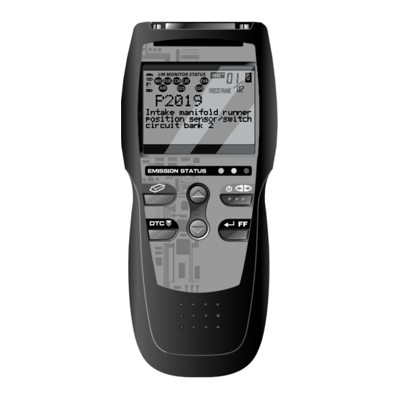
Tool Controls DISPLAY FUNCTIONS DISPLAY FUNCTIONS 11 12 13 Figure 2. Display Functions See Figure 2 for the locations of items 1 through 16, below. 1. I/M MONITOR STATUS field - Identifies the I/M Monitor status area. (This function is applicable to OBD2 systems only.) 2. - Page 14 Tool Controls DISPLAY FUNCTIONS 7. DTC Display Area - Displays the Diagnostic Trouble Code (DTC) number. Each fault is assigned a code number that is specific to that fault. 8. Test Data Display Area - Displays DTC definitions, Freeze Frame data, and other pertinent test information messages.
-
Page 15: Viewing Dtcs In The Tool's Memory
Tool Controls VIEWING DTCs IN THE TOOL’S MEMORY VIEWING DTCs IN THE TOOL’S MEMORY To view DTC’s and other diagnostic data stored in the Tool’s memory, do the following: 1. With no DLC cable connected to the Tool, press the POWER/LINK button to turn the Tool “on”. -
Page 16: Preparation For Testing
Preparation for Testing PRELIMINARY VEHICLE DIAGNOSTIC WORKSHEET PRELIMINARY VEHICLE DIAGNOSTIC WORKSHEET The purpose of this form is to help you gather preliminary information on your vehicle before you retrieve codes. By having a complete account of your vehicle's current problem(s), you will be able to systematically pinpoint the problem(s) by comparing your answers to the fault codes you retrieve. - Page 17 Preparation for Testing PRELIMINARY VEHICLE DIAGNOSTIC WORKSHEET WHEN DID YOU FIRST NOTICE THE PROBLEM: ❏ Just Started ❏ Started Last Week ❏ Started Last Month ❏ Other: LIST ANY REPAIRS DONE IN THE PAST SIX MONTHS: PROBLEMS STARTING ❏ ❏ No symptoms Cranks, but will not start ❏...
- Page 18 Preparation for Testing PRELIMINARY VEHICLE DIAGNOSTIC WORKSHEET AUTOMATIC TRANSMISSION PROBLEMS (if applicable) ❏ ❏ No symptoms Vehicle does not move when in gear ❏ Shifts too early or too late ❏ Jerks or bucks ❏ Changes gear incorrectly PROBLEM OCCURS ❏...
-
Page 19: Before You Begin
Preparation for Testing BEFORE YOU BEGIN BEFORE YOU BEGIN The Enhanced OBD2 & 1 Tool aids in monitoring electronic- and emissions-related faults in your vehicle and retrieving fault codes related to malfunctions in these systems. Mechanical problems such as low oil level or damaged hoses, wiring or electrical connectors can cause poor engine performance and may also cause a fault code to set. -
Page 20: Vehicle Service Manuals
Preparation for Testing VEHICLE SERVICE MANUALS VEHICLE SERVICE MANUALS Always refer to the manufacturer’s service manual for your vehicle before performing any test or repair procedures. Contact your local car dealership, auto parts store or bookstore for availability of these manuals. -
Page 21: General Code Retrieval Procedures
General Code Retrieval Procedures OBD1 SYSTEMS / OBD2 SYSTEMS Procedures for Retrieving Diagnostic Trouble Codes from OBD1 systems are vehicle manufacturer specific. Each manufacturer uses their own procedure. Procedures for retrieving Diagnostic Trouble Codes from OBD2 systems are generic, and apply to all vehicles equipped with OBD2 systems. From the following list, select the procedure that applies to your vehicle’s OBD system, and proceed to appropriate section for detailed code retrieval procedures. -
Page 22: Vehicles Covered
OBD2 Systems VEHICLES COVERED VEHICLES COVERED The Enhanced OBD2 & 1 Tool is designed to work on all OBD2 compliant vehicles. All 1996 and newer vehicles (cars and light trucks) sold in the United States are OBD2 compliant. Federal law requires that all 1996 and newer cars and light trucks sold in the United States must be OBD2 compliant;... -
Page 23: Diagnostic Trouble Codes (Dtcs)
OBD2 Systems DIAGNOSTIC TROUBLE CODES (DTCs) On some Asian and European vehicles the DLC is located behind the “ashtray” (the ashtray must be removed to access it) or on the far left corner of the dash. If the DLC cannot be located, consult the vehicle’s service manual for the location. - Page 24 OBD2 Systems DIAGNOSTIC TROUBLE CODES (DTCs) OBD2 DTC EXAMPLE P0201 - Injector Circuit Malfunction, Cylinder 1 P 0 2 0 1 Body Chassis Powertrain Network Generic Manufacturer Specific Generic Includes both Generic and Manufacturer Specific Codes Identifies the system where the problem is located: Fuel and Air Metering Fuel and Air Metering (injector circuit...
-
Page 25: Code Retrieval Procedure
OBD2 Systems CODE RETRIEVAL PROCEDURE CODE RETRIEVAL PROCEDURE Retrieving and using Diagnostic Trouble Codes (DTCs) for troubleshooting vehicle operation is only one part of an overall diagnostic strategy. Never replace a part based only on the DTC definition. Each DTC has a set of testing procedures, instructions and flow charts that must be followed to confirm the location of the problem. - Page 26 OBD2 Systems CODE RETRIEVAL PROCEDURE If replacing the fuse(s) does not correct the problem, consult your vehicle’s repair manual to identify the proper computer (PCM) fuse/circuit, and perform any necessary repairs before proceeding. 5. Turn the ignition on. DO NOT start the engine. 6.
- Page 27 OBD2 Systems CODE RETRIEVAL PROCEDURE The Tool will display a code only if codes are present in the vehicle’s computer memory. If no codes are present, a “No DTC’s are presently stored in the vehicle’s computer” message is displayed. The Tool is capable of retrieving and storing up to 32 codes in memory, for immediate or later viewing.
- Page 28 OBD2 Systems CODE RETRIEVAL PROCEDURE The green, yellow and red LEDs are used (with the LCD display) as visual aids to make it easier to determine engine system conditions. Green LED – Indicates that all engine systems “OK” operating normally. All monitors supported by the vehicle have run performed their...
- Page 29 OBD2 Systems CODE RETRIEVAL PROCEDURE DTC’s that start with “P1” and some “P3” Manufacturer Specific codes and their code definitions vary with each vehicle manufacturer. When a Manufacturer Specific DTC is retrieved, the LCD display shows a list of vehicle manufacturers. Use the UP and DOWN buttons,...
- Page 30 OBD2 Systems CODE RETRIEVAL PROCEDURE If more than one malfunction is present that causes more than one DTC to be set, only the code with the highest priority will contain Freeze Frame data. The code designated “01” on the Tool display is referred to as the PRIORITY code, and Freeze Frame data always refers to this code.
-
Page 31: Viewing Enhanced Data
OBD2 Systems VIEWING ENHANCED DATA VIEWING ENHANCED DATA Following the code retrieval procedure (see CODE RETRIEVAL PROCEDURE on page 23), when the last retrieved DTC has been displayed and the DTC SCROLL button is pressed, the Tool enters the “enhanced” mode. The “enhanced” mode provides the ability to retrieve enhanced DTCs from most Chrysler/Jeep, Ford/Mazda, GM/Isuzu, Honda/Acura and Toyota/Lexus vehicles. - Page 32 OBD2 Systems VIEWING ENHANCED DATA If a Manufacturer specific DTC was retrieved, and the manufacturer selected for the code was not Chrysler, Jeep, Ford, Mazda, General Motors, Isuzu, Honda, Acura, Toyota or Lexus, the View Vehicle Information confirmation message displays. Press the ENTER/FF button to view vehicle information, or, press the DTC...
- Page 33 OBD2 Systems VIEWING ENHANCED DATA 2. To read the display: Refer to DISPLAY FUNCTIONS on page 11 for a description of LCD display elements. A visible icon indicates that the Tool is being powered through the vehicle’s DLC connector. A visible icon indicates that the Tool is linked to (communicating with) the vehicle’s computer.
- Page 34 OBD2 Systems VIEWING ENHANCED DATA Ford/Mazda Enhanced DTCs Mazda Enhanced DTCs are available for Mazda-branded Ford vehicles only. When Ford/Mazda is selected from the Enhanced DTCs Main menu, the Ford/Mazda Enhanced menu displays. You may view DTCs for either the “Continuous Memory Test”, “KOEO (Key On Engine Off) Test” or “KOER (Key On Engine Running) Test.”...
- Page 35 OBD2 Systems VIEWING ENHANCED DATA I/M MONITOR STATUS icons are not displayed when viewing enhanced DTCs. In the case of long code definitions, or when viewing Freeze Frame data, a small arrow is shown in the upper/lower right-hand corner of the code display area to indicate the presence of additional information.
- Page 36 OBD2 Systems VIEWING ENHANCED DATA If the Tool fails to link to the vehicle’s computer, “Linking Failed” message shows Tool’s display. - Verify the ignition is ON, then press the ENTER/FF button to continue. 2. To read the display: Refer to DISPLAY FUNCTIONS on page 11 for a description of LCD display elements.
- Page 37 OBD2 Systems VIEWING ENHANCED DATA 4. When the last retrieved DTC has been displayed and the DTC SCROLL button is pressed, the Tool returns to the GM/Isuzu Enhanced menu. To view additional enhanced DTCs, repeat steps 1 through 4, above. To exit the enhanced mode, use the UP and DOWN buttons, as necessary, to select Exit from the GM/Isuzu...
- Page 38 OBD2 Systems VIEWING ENHANCED DATA The Diagnostic Trouble Code (DTC) and related code definition are shown in the lower section of the LCD display. MONITOR STATUS icons are not displayed when viewing enhanced DTCs. In the case of long code definitions, or when viewing Freeze Frame data, a small arrow is shown in the upper/lower right-hand corner of the code display area to indicate the presence of additional information.
- Page 39 OBD2 Systems VIEWING ENHANCED DATA Current DTCs or History DTCs Current DTCs, Historical DTCs Readiness DTCs 1. Use the UP and DOWN buttons, as necessary, to highlight the desired option, then press the ENTER/FF button. A “One moment please” message displays, while the Tool retrieves the selected DTCs.
-
Page 40: Viewing Vehicle Information
OBD2 Systems VIEWING VEHICLE INFORMATION 3. If more than one code was retrieved press the DTC SCROLL button, as necessary, to display additional codes one at a time. Whenever the Scroll function is used to view additional codes, the Tool’s communication link with the vehicle’s computer disconnects. -
Page 41: Erasing Diagnostic Trouble Codes (Dtcs)
OBD2 Systems ERASING DIAGNOSTIC TROUBLE CODES (DTCs) 1. On the Vehicle Information menu, use the UP and DOWN buttons, as necessary, to highlight Vehicle ID, then press the ENTER/FF button. 2. A "One moment please..." message displays while the requested information is retrieved from the vehicle's computer. - Page 42 OBD2 Systems ERASING DIAGNOSTIC TROUBLE CODES (DTCs) If you plan to take the vehicle to a Service Center for repair, DO NOT erase the codes from the vehicle's computer. If the codes are erased, valuable information that might help the technician troubleshoot the problem will also be erased.
-
Page 43: I/M Readiness Testing
OBD2 Systems I/M READINESS TESTING If the erase was successful, a confirmation message shows on the LCD display. Press the POWER/LINK button to return to the DTC screen. If the erase was not successful, an advisory message shows on the LCD display. - Page 44 OBD2 Systems I/M READINESS TESTING detect and report any problems or faults that may increase the vehicle's emissions to an unacceptable level. The vehicle's emissions control system consists of several components or sub-systems (Oxygen Sensor, Catalytic Converter, EGR, Fuel System, etc.) that aid in reducing vehicle emissions. To have an efficient Vehicle Emission Control System, all the emissions- related components and systems must work correctly whenever the vehicle is in operation.
- Page 45 OBD2 Systems I/M READINESS TESTING The Tool allows you to retrieve Monitor/System Status Infor-mation to help you determine if the vehicle is ready for an Emissions Test (Smog Check). In addition to retrieving Diagnostic Trouble Codes, the Tool also retrieves Monitor Run/Not Run status. This information is very important since different areas of the state/country have different emissions laws and regulations concerning Monitor Run/Not Run status.
- Page 46 OBD2 Systems I/M READINESS TESTING If a "PENDING" Diagnostic Trouble Code is causing the yellow LED to light, it is possible that the vehicle will be allowed to be tested for emissions and certified. Currently, most areas (states) will allow an Emissions Test (Smog Check) to be performed if the only code in the vehicle's computer is a "PENDING"...
- Page 47 OBD2 Systems I/M READINESS TESTING Take the vehicle to a professional to have it serviced. The problem(s) causing the red LED to light must be repaired before the vehicle is ready for an Emissions Test (Smog Check). Using the I/M Readiness Monitor Status to Confirm a Repair The I/M Readiness Monitor Status function can be used (after repair of a fault has been performed) to confirm that the repair has been performed correctly, and/or to check for Monitor Run Status.
- Page 48 OBD2 Systems I/M READINESS TESTING If, after the Monitor has run, the MIL on the vehicle's dash is not lit, and no stored or pending codes associated with that particular Monitor are present in the vehicle's computer, the repair was successful. If, after the Monitor has run, the MIL on the vehicle's dash lights and/or a DTC associated with that Monitor is present in the vehicle's computer, the repair was unsuccessful.
-
Page 49: Chrysler/Jeep Obd1 Systems
Chrysler/Jeep OBD1 Systems CHRYSLER/JEEP OBD1 SYSTEMS CHRYSLER/JEEP OBD1 SYSTEMS Chrysler Motors On-Board Computer Systems Chrysler Motors introduced its first electronic fuel injected vehicle in late 1983. The on-board computer management systems used on Chrysler vehicles have evolved over the years, and their names have changed accordingly. -
Page 50: Vehicles Covered
Chrysler/Jeep OBD1 Systems VEHICLES COVERED / PANEL INDICATOR LIGHTS / DLC VEHICLES COVERED This section covers Chrysler fuel injected vehicles from 1983-1995. Model Type Year Model Passenger 1983-1995 Chrysler, Dodge and Plymouth Fuel Cars Injected Models Only (Excluding Lasor/Talon 1.8L, 2.0L (ALL YEARS), 1990 Monaco/Premier, 1993-1995 Intrepid, LHS, Concorde and Vision, 1995 Avenger, Stealth (ALL YEARS) and Cirrus 2.5L (ALL... -
Page 51: Code Retrieval Procedure
Chrysler/Jeep OBD1 Systems CODE RETRIEVAL PROCEDURE CODE RETRIEVAL PROCEDURE Retrieving and using Diagnostic Trouble Codes (DTCs) for troubleshooting vehicle operation is only one part of an overall diagnostic strategy. Never replace a part based only on the DTC definition. Each DTC has a set of testing procedures, instructions and flow charts that must be followed to confirm the location of the problem. - Page 52 Chrysler/Jeep OBD1 Systems CODE RETRIEVAL PROCEDURE - From “Current Selection/ Select Vehicle” screen, highlight Current Selection and press the ENTER/FF button. - Proceed to step 5 to continue. To retrieve DTCs from a new vehicle: - From the “Current Selection/Select New Vehicle”...
- Page 53 Chrysler/Jeep OBD1 Systems CODE RETRIEVAL PROCEDURE - Press the ENTER/FF button and repeat steps 4 through 6 as necessary. 7. If the Tool was able to link to the vehicle successfully a "Code retrieval was successful..." message shows tempo- rarily on the Tool’s LCD display followed by any retrieved DTCs.
-
Page 54: Ford Obd1 Systems
Ford OBD1 Systems FORD COMPUTER SYSTEM OVERVIEW - VEHICLES COVERED FORD COMPUTER SYSTEM OVERVIEW The Enhanced OBD2 & 1 Tool is compatible only with EEC-IV Computer Control systems. IMPORTANT: When the computer is in Self-Test mode (is testing the sensors or actuators for proper operation), it relies on voltage signals that is sends to and / or receives from the sensors or actuators to determine whether or not these components are operating properly. - Page 55 Ford OBD1 Systems VEHICLES COVERED - CARS Fuel Systems (Carburetor Computer Engine Digit** Model) Application/Special Notes System 1984-1986 (Cont) 5.0L V-8 F, M CFI, SEFI Capri, Continental, Colony EEC-IV Park, Cougar, Country Squire, Crown Victoria, Grand Marquis, LTD, Mark VII, Marquis, Mustang, T-Bird, Town Car 1987-1993...
- Page 56 Ford OBD1 Systems VEHICLES COVERED - TRUCKS/VANS Fuel Systems (Carburetor Computer Engine Digit** Model) Application/Special Notes System 1995 (Cont) 4.6L V8 DOHC Mark VIII EEC-IV 5.0L V-8 HO Mustang 5.0L V-8 SHP NOTES * Carburetor Model. Carburetor model numbers are usually stamped on top of the carburetor, or on a metal tab attached to the carburetor.
-
Page 57: Test Connectors
Ford OBD1 Systems VEHICLES COVERED – TRUCKS/VANS - TEST CONNECTORS Fuel Systems (Carburetor Computer Engine Digit** Model) Application/Special Notes System 1991-1994 (Cont) 4.0L V-6 EFI, MFI Aerostar, Explorer, Ranger EEC-IV 4.9L I-6 Y, H EFI, MFI, SFI Bronco, E and F Series Trucks/Vans (8500 lb. -
Page 58: Connecting The Tool
Ford OBD1 Systems CONNECTING THE TOOL – DIAGNOSTIC TROUBLE CODES (DTCs) Near the front corner (right or left). Near the fender well (right or left). Near the fire wall (right or left). CONNECTING THE TOOL The Tool's Ford Connector Cable Adaptor is designed to match the vehicle's computer DLC. -
Page 59: Code Retrieval Procedures
Ford OBD1 Systems CODE RETRIEVAL PROCEDURES - OVERVIEW - KOEO TEST fault code will be stored in memory as a history DTC. If the malfunction that caused the history DTC to set does not recur within a predetermined length of time (usually within 40-80 ignition key start cycles), the computer will automatically erase the related fault code from its memory. - Page 60 Ford OBD1 Systems CODE RETRIEVAL PROCEDURES - KOEO TEST Check your vehicle thoroughly before performing any test. See BEFORE YOU BEGIN on page 17 for details. ALWAYS observe safety precautions whenever working on a vehicle. See Safety Precautions on page 3 for more informa- tion.
- Page 61 Ford OBD1 Systems CODE RETRIEVAL PROCEDURES - KOEO TEST As soon as the ignition is turned "on", the vehicle's computer enters the Self-Test mode. Clicking sounds will be heard coming from the engine. This is normal. It indicates that the vehicle's computer is activating relays, solenoids, and other components to check their operation.
- Page 62 Ford OBD1 Systems CODE RETRIEVAL PROCEDURES – ENGINE TIMING CHECK In the case of long code definitions, a small arrow is shown in the upper/lower right-hand corner of the code display area to indicate the presence of additional information. Use the buttons, as necessary, to view the additional information.
- Page 63 Ford OBD1 Systems CODE RETRIEVAL PROCEDURES – ENGINE TIMING CHECK following "Timing Check" procedure only applicable to 1992 and older vehicles (excluding diesel engines). For 1993 and newer vehicles, refer to the vehicle's service repair manual for procedures to check and adjust timing.
- Page 64 Ford OBD1 Systems ADDITIONAL TESTS FOR EEC-IV SYSTEMS – KOER TEST A "One moment please preparation for test is in progress: message shows temporarily on the Tool's display, followed message "Perform Timing Check within two minutes." 7. When "Perform Timing Check within 2 minutes"...
- Page 65 Ford OBD1 Systems CODE RETRIEVAL PROCEDURES - KOER TEST Ignition timing and timing advance must be operating properly in order for the KOER Self-Test results to be considered valid. Perform an Engine Timing check (page 60) before performing the KOER Self-Test. Check your vehicle thoroughly before performing any test.
- Page 66 Ford OBD1 Systems CODE RETRIEVAL PROCEDURES – KOER TEST Quickly press the accelerator pedal to the floor and then release 8. After above procedures performed a "One moment please KOER test is in progress..." message shows temporarily on the Tool's LCD display, followed "Retrieving...
-
Page 67: Additional Tests For Eec-Iv Systems
Ford OBD1 Systems ADDITIONAL TESTS FOR EEC-IV SYSTEMS – CYLINDER BALANCE TEST See VIEWING DTCs IN THE TOOL’S MEMORY on page 13 to view DTCs stored in the Tool's memory. All retrieved DTCs will remain in the Tool's memory. If the KOER Test procedure is performed again, DTC's from a prior test will automatically clear and will be replaced by the most current DTCs retrieved. - Page 68 Ford OBD1 Systems ADDITIONAL TESTS FOR EEC-IV SYSTEMS - CYLINDER BALANCE TEST multi-port fuel injection systems, the injectors all fire at the same time and at every engine revolution. On other systems the injectors fire in groups and/or at every other engine revolution. What distinguishes Sequential Electronic Fuel Injection systems from other multi-port fuel injection systems is that each injector is independently energized and fires sequentially one after the other in the proper firing order.
- Page 69 Ford OBD1 Systems ADDITIONAL TESTS FOR EEC-IV SYSTEMS – CYLINDER BALANCE TEST 7. When prompted by the message on the Tool's display, lightly press accelerator pedal half way and release to activate the cylinder balance test. For 1986 models ONLY: Fully press accelerator once and re- lease.
- Page 70 Ford OBD1 Systems ADDITIONAL TESTS FOR EEC-IV SYSTEMS - RELAY AND SOLENOID TEST 12. After the repeat Cylinder Balance tests have completed, the computer will identify which cylinder (or cylinders) are not contributing equally, and will send this information to the Tool’s LCD display.
- Page 71 Ford OBD1 Systems ADDITIONAL TESTS FOR EEC-IV SYSTEMS - RELAY AND SOLENOID TEST 4. Start and warm-up engine to normal operating temperature. Press the ENTER/FF button to continue. 5. Turn ignition key OFF and wait for the on screen prompt. If you wish to exit the Output State Check at this time, press the ENTER/FF button.
- Page 72 Ford OBD1 Systems ADDITIONAL TESTS FOR EEC-IV SYSTEMS - WIGGLE TEST 9. If the Tool was able to link to the vehicle successfully an "Output State check active..." message shows temporarily on the Tool's LCD display. This message is followed by a display that instructs you how to perform the test.
- Page 73 Ford OBD1 Systems ADDITIONAL TESTS FOR EEC-IV SYSTEMS - WIGGLE TEST 1986 & Newer - Pressure Feedback EGR Sensor (PFE) 1990 & Newer - Exhaust Gas Oxygen Sensor (EGO), Ignition Diagnostic Monitor (IDM) (DIS or Dual Plug DIS only), Idle Tracking Switch (ITS), Mass Air Flow Sensor (MAF) ALWAYS observe safety precautions whenever working on a vehicle.
- Page 74 Ford OBD1 Systems ADDITIONAL TESTS FOR EEC-IV SYSTEMS - WIGGLE TEST For KOEO Wiggle Test: - Verify the ignition is ON. - Turn the ignition OFF, wait 10 seconds, then turn back ON to reset the computer. Press the ENTER/FF button to continue.
-
Page 75: Gm Obd1 Systems
GM OBD1 Systems YOUR VEHICLE’S COMPUTER SYSTEM - VEHICLES COVERED YOUR VEHICLE'S COMPUTER SYSTEM Today's vehicles are equipped with computer self-testing abilities that can locate problems in your vehicle and store them as Diagnostic Trouble Codes (DTC's) in the vehicle's onboard computer. The Tool allows you access to the computer's memory and retrieves the DTC's. -
Page 76: About The Tool
GM OBD1 Systems ABOUT THE TOOL - DLC – MIL - DTCs In addition to the list on the previous page, this Tool IS ALSO COMPATIBLE with OBD1 GM models that are equipped with "Climate Control Computers". For 1994 and 1995 vehicles, only the models listed above are compatible with the Tool. -
Page 77: Code Retrieval Procedure
GM OBD1 Systems CODE RETRIEVAL PROCEDURE Intermittent/History DTCs Intermittent/History DTCs are stored in the computer's memory for problems that occur intermittently, or for problems that happened in the past but are not currently present. Intermittent DTCs may cause the Malfunction Indicator light to flicker or stay on until the intermittent malfunction goes away. - Page 78 GM OBD1 Systems CODE RETRIEVAL PROCEDURE If a previous vehicle selection is currently saved in the Tool's memory, the "Current Selection/Select New Vehicle" menu displays. If no previous vehicle selection is stored in the Tool's memory, "Select New Vehicle" displays. Use the buttons, as necessary, to make menu selections.
- Page 79 GM OBD1 Systems CODE RETRIEVAL PROCEDURE If the Tool fails to link to the vehicle's computer, a "Vehicle is not responding" message shows on the Tool’s LCD display. Do the following: Verify the ignition is ON. Check the cable connections at the Tool and at the vehicle’s DLC.
- Page 80 GM OBD1 Systems CODE RETRIEVAL PROCEDURE (see Servicing DTCs on page 88) and retesting after each repair is made to be sure the fault was eliminated. Code 12 will appear alone when no other fault codes are present. It may be necessary to test drive the vehicle to reset "hard" fault codes 13, 15, 24, 44, 45, and 55 after they have been erased.
-
Page 81: Toyota/Lexus Obd1 Systems
Toyota/Lexus OBD1 Systems ON-BOARD VEHICLE DIAGNOSTICS / VEHICLES COVERED ON-BOARD VEHICLE DIAGNOSTICS (OBD1) Beginning in 1988, California's Air Resources Board (CARB), and later, the Federal Government's Environmental Protection Agency (EPA), required vehicle manufacturers to include a self diagnostic program capable of identifying an emissions-related fault via the vehicles On-Board Computers (some manufacturers used OBD before it was required). - Page 82 Toyota/Lexus OBD1 Systems VEHICLES COVERED DOHC/ Eng. Eng. Year Model Size Code SOHC Other Type 1992 Celica 2.2L 5S-FE DOHC Convertible 1992 Celica Coupe 1.6L 4A-FE DOHC 1992 Celica Coupe 2.2L 5S-FE DOHC 1993 Celica Coupe 1.6L 4A-FE DOHC 1995 Celica Coupe 1.8L 7A-FE...
- Page 83 Toyota/Lexus OBD1 Systems VEHICLES COVERED DOHC/ Eng. Eng. Year Model Size Code SOHC Other Type 1993 Supra 3.0L 2JZ-GTE DOHC Turbo 1993 Supra 3.0L 2JZ-GE DOHC 1994 Camry 3.0L 3VZ-FE DOHC 1994 Supra 3.0L 2JZ-GTE DOHC Turbo 1994 Supra 3.0L 2JZ-GE DOHC 1995...
-
Page 84: Data Link Connector (Dlc)
Toyota/Lexus OBD1 Systems DATA LINK CONNECTOR (DLC) / MIL DATA LINK CONNECTOR (DLC) Toyota vehicles are equipped with special Test Connectors that make it possible to connect specialized testing equipment that communicates with the vehicle's onboard computer. This Tool is designed for use with two types of Toyota DLC connectors;... -
Page 85: Diagnostic Trouble Codes
Toyota/Lexus OBD1 Systems DIAGNOSTIC TROUBLE CODES / CODE RETRIEVAL PROCEDURE If your instrument panel indicator lights do not come on when you turn on the ignition, please refer to your vehicle's service manual. You may have problems in the car's circuitry. It is recommended that you fix these problems before retrieving DTCs from your vehicle’s computer. - Page 86 Toyota/Lexus OBD1 Systems CODE RETRIEVAL PROCEDURE Check your vehicle thoroughly before performing any test. See BEFORE YOU BEGIN on page 17 for details. ALWAYS observe safety precautions whenever working on a vehicle. See Safety Precautions on page 3 for more information.
- Page 87 Toyota/Lexus OBD1 Systems CODE RETRIEVAL PROCEDURE The Tool will display a code only if codes are present in the vehicle's computer memory. If no codes are present, a "No DTC' are presently stored in the vehicle's computer" message is displayed. 7.
-
Page 88: Servicing Dtcs
Servicing DTCs OBD1 SERVICING DTCs - OBD I Retrieving and using Diagnostic Trouble Codes (DTCs) for troubleshooting vehicle operation is only one part of an overall diagnostic strategy. Never replace a part based only on the DTC definition. Each DTC has a set of testing procedures, instructions and flow charts that must be followed to confirm the location of the problem. -
Page 89: Servicing Dtcs
Servicing DTCs OBD1 4. Red LED - Indicates there is a problem with one or more of the vehicle's systems. The red LED is also used to indicate that DTC(s) present (displayed Tool's screen). In this case, the MIL or Check Engine light on the vehicle's instrument panel will be illuminated. -
Page 90: Erasing Dtcs (Obd I Systems)
Erasing DTCs OBD1 SYSTEMS ERASING DTCs (OBD I SYSTEMS) When the Tool's ERASE function is used to erase DTCs from the vehicle's on-board computer, manufacturer specific data (where applicable) is also erased. If you plan to take the vehicle to a service center for repair, DO NOT erase the codes from the vehicle's computer. - Page 91 Erasing DTCs OBD1 SYSTEMS If the erase was not successful, an advisory message shows on the LCD display. Verify that the Tool is properly connected to the vehicle's DLC and that the ignition is ON. If the erase process still does not complete, turn the ignition OFF, wait 10 seconds, then turn back ON and repeat steps 2 and 3.
-
Page 92: Glossary Of Terms And Abbreviations
Glossary GLOSSARY OF TERMS AND ABBREVIATIONS GLOSSARY OF TERMS AND ABBREVIATIONS CARB – California Air Resources Board CCM – Central Control Module Computer Control System – An electronic control system, consisting of an on-board computer and related sensors, switches and actuators, used to ensure peak performance and fuel efficiency while reducing pollutants in the vehicle’s emissions. - Page 93 Glossary GLOSSARY OF TERMS AND ABBREVIATIONS OBD2 – On-Board Diagnostics Version 2 (also referred to as “OBD II”) On-Board Computer – The central processing unit in the vehicle’s computer control system. PCM – Powertrain Control Module Pending Code – A code recorded on the “first trip” for a “two-trip” code. If the fault that caused the code to be set is not detected on the second trip, the code is automatically erased.
- Page 94 Notes OBD2 & 1...
-
Page 95: Warranty And Servicing
Warranty and Servicing LIMITED ONE YEAR WARRANTY The Manufacturer warrants to the original purchaser that this unit is free of defects in materials and workmanship under normal use and maintenance for a period of one (1) year from the date of original purchase. - Page 96 ® Innova Electronics Corp. 17291 Mt. Herrmann Street Fountain Valley, CA 92708 PRODUCT DESIGN & COPYRIGHT Printed in Taiwan Instruction MRP #93-0092 Rev. B © 2007 Copyright © 2007 IEC. All Rights Reserved.
Need help?
Do you have a question about the 3120 and is the answer not in the manual?
Questions and answers