Table of Contents
Advertisement
Quick Links
THE PRESENT MANUAL IS FOR REFERENCE ONLY AND MIGHT BE NOT UP TO DATE TO THE LATEST
VERSION.PLEASE CONTACT US FOR GETTING THE MOST UPDATED FILE
Via Montefeltro, 6 – 20156 Milano (MI) – Italy
Tel. +39 (02) 3088583 – Fax +39 (02) 33406697
www.blinkmarine.com – info@blinkgroup.com
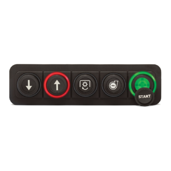
PKP-1500-LI
CANOPEN USER MANUAL
FOR REFERENCE
ONLY
Advertisement
Table of Contents

Subscribe to Our Youtube Channel
Related Manuals for Blink Marine PKP-1500-LI


Summary of Contents for Blink Marine PKP-1500-LI
- Page 1 PKP-1500-LI CANOPEN USER MANUAL THE PRESENT MANUAL IS FOR REFERENCE ONLY AND MIGHT BE NOT UP TO DATE TO THE LATEST VERSION.PLEASE CONTACT US FOR GETTING THE MOST UPDATED FILE Via Montefeltro, 6 – 20156 Milano (MI) – Italy Tel. +39 (02) 3088583 – Fax +39 (02) 33406697 www.blinkmarine.com – info@blinkgroup.com FOR REFERENCE ONLY...
-
Page 2: Table Of Contents
Table of contents 1. How to connect the wires: ..................3 2. Reference ........................4 3. Default settings ......................5 NMT MESSAGES ........................5 4. Start CANopen node (keypad activation message) ............. 5 5. Enter pre-operational ....................5 6. Reset CANopen node ....................6 7. Stop CANopen node ....................6 8. Boot-up service ......................6 9. Heartbeat message ...................... 6 10. Sync message ......................7 PDO messages ........................7 11. Keys state message ..................... 7 -PKP 1500LI ........................ 7 12. Set LED ON message . -
Page 3: How To Connect The Wires
c) Backlight color ......................14 d) Default backlight color .................... 14 e) Default LED indicators brightness level ..............15 f) Default backlight brightness level ................16 20. Object 2010h: Baud rate setting ................16 21. Object 2011h: Set Boot-up service ................17 22. Object 2012h: Set device active on startup ............... 18 23. Object 2013h: Set CANopen node ID ................ 18 24. Object 2014h: Set startup LED show ................. 19 25. Object 2100h: Set DEMO mode ................. 20 26. Object 1016h: Consumer heartbeat time ..............20 27. Object 1017h: Producer heartbeat time ..............21 Heartbeat message ......................21 28. Object 1000h: Device Type ..................22 29. Object 1001h: Error Register ..................22 30. Object 1008h: Manufacturer Device Name . -
Page 4: Reference
1. How to connect Deutsch 4 pin: PIN COLOUR FUNCTION Blue CAN L White CAN H Black Negative battery Red Vbatt. (12-24V) Each end of the CAN bus is terminated with 120Ω resistors in compliance with the standard to minimize signal reflections on the bus. You may need to place a 120Ω resistor between CAN-L and CAN-H. -
Page 5: Default Settings
3. Default settings Default state or level How to change Setting Baud Rate 125 kbit/s Object 2010h CANopen Node ID Object 2013h Device active on startup Not active Object 2012h Default LED indicators 3Fh (Maximum Brightness) Object 2003h brightness Default backlight brightness 00h (OFF) Object 2003h Default backlight color... -
Page 6: Reset Canopen Node
6. Reset CANopen node Identifier Byte 0 Reset CANopen node Keypad CAN ID Byte 1 00h: reset all the keypads 15h: reset the keypad with CAN ID = 15h. Byte 2, 7 Not used Example: Direction Identifier Format Message To Keypad 81 15 7. -
Page 7: Sync Message
10. Sync message This mechanism modifies the PDO operation in the following way: both the RPDOs and TPDOs are stored at the receiving of the 1 SYNC message but, while the RPDOs are always processed with the arrival of next one, the TPDOs are transmitted each n-th time the SYNC message is received depending on the value chosen for transmission type. -
Page 8: Set Led On Message
12. Set LED ON message The keypad must be activated, see NMT Start CANopen Node message. PKP 1500LI • Identifier 200h + current CAN ID Default 215h Byte 0 0 0 0 R5 – R4 R3 R2 R1 Red LED Byte 1 0 0 0 G5 –... -
Page 9: Led Indicators Brightness Level
14. LED indicators brightness level The keypad must be activated, see NMT Start CANopen Node message. Identifier 400h + current CAN ID Default 415h Byte 0 Intensity 00h-3Fhà min-100% Byte 1, 7 Not used Examples: Direction Identifier Format Message To Keypad 1F 00 00 00 00 00 00 00 Brightness = 50% To Keypad... -
Page 10: Object 2001H: Digital Output Module
Examples: Direction Identifier Format Message Data 40 00 20 01 00 00 00 00 Read keys state Keypad Keypad 4F 00 20 01 00 00 00 00 No Key pressed reply 4F 00 20 01 01 00 00 00 Key 1 pressed 4F 00 20 01 02 00 00 00 Key 2 pressed 4F 00 20 01 04 00 00 00... -
Page 11: B) Read Led On
b) Read LED ON The LED have the same mapping of Set LED ON message • PKP 1500LI Identifier 600h + current CAN ID Default 615h Byte 0 Read Device Register Byte 1 CAN Object 2001h Byte 2 Byte 3 XX: Sub index 01h: Red LED 02h: Green LED... -
Page 12: B) Read Led Blink
Examples: Direction Identifier Format Message Data To Keypad 2F 02 20 01 01 00 Set red LED #1 00 00 blink Keypad reply 60 02 20 01 00 00 Command 00 00 accepted To Keypad 2F 02 20 03 10 00 Set blue LED #5 00 00 blink... -
Page 13: B) Backlight Brightness Level
Identifier 615h (600h + current CAN ID) Byte 0 Read Device Register Byte 1 CAN Object 2003h Byte 2 Byte 3 Sub index Byte 4,7 Not used Example: Direction Identifier Format Message Data To Keypad 2F 03 20 01 0D 00 Brightness = 25% 00 00 Keypad... -
Page 14: C) Backlight Color
c) Backlight color Set message: Identifier 615h (600h + current CAN ID) Byte 0 Set Device Register Byte 1 CAN Object 2003h Byte 2 Byte 3 Sub index Byte 4 Color 05h: cyan 01h: red 06h: violet 02h: green 07h: white/light 03h: blue blue 04h: yellow... -
Page 15: E) Default Led Indicators Brightness Level
Read message: Identifier 615h (600h + current CAN ID) Byte 0 Read Device Register Byte 1 CAN Object 2003h Byte 2 Byte 3 Sub index Byte 4,7 Not used Example: Direction Identifier Format Message Data To Keypad 2F 03 20 04 04 00 00 Yellow backlight color Keypad 60 03 20 04 00 00... -
Page 16: F) Default Backlight Brightness Level
f) Default backlight brightness level Set message: Identifier 615h (600h + current CAN ID) Byte 0 Set Device Register Byte 1 CAN Object 2003h Byte 2 Byte 3 Sub index Byte 4 Intensity 00h-3Fhà 0-100% Byte 5,7 Not used Read message: Identifier 615h (600h + current CAN ID) Byte 0... -
Page 17: Object 2011H: Set Boot-Up Service
Read message: Identifier 615h (600h + current CAN ID) Byte 0 Read Device Register Byte 1 CAN Object 2010h Byte 2 Byte 3 Sub index Byte 4,7 Not used Example: Direction Identifier Format Message Data To Keypad 2F 10 20 00 02 00 Baud rate = 500k 00 00 Keypad... -
Page 18: Object 2012H: Set Device Active On Startup
22. Object 2012h: Set device active on startup If keypad is active on startup don’t need the Start CANopen command from host. Set message: Identifier 600h + current CAN ID Default 615h Byte 0 Set Device Register Byte 1 CAN Object 2012h Byte 2 Byte 3 Sub index... -
Page 19: Object 2014H: Set Startup Led Show
Example: Direction Identifier Format Message Data To Keypad 615 2F 13 20 00 17 00 00 00 CANopen node ID set to Keypad 60 13 20 00 00 00 00 00 Command accepted reply To Keypad 617 40 13 20 00 00 00 00 00 Read CANopen node ID Keypad 4F 13 20 00 17 00 00 00... -
Page 20: Object 2100H: Set Demo Mode
25. Object 2100h: Set DEMO mode This message enables the Demo mode function. Demo mode is a special feature that consists in different LED states for each button pressing. Refer to the appendix “Demo mode instructions” to try these special features. Disconnect and reconnect the keypad after the sending the message to enter this mode. -
Page 21: Object 1017H: Producer Heartbeat Time
Heartbeat time: XXYYh (from 000Ah to FFFFh: from 10 to 65535 milliseconds) When the period is set to 0000h, the consumer heartbeat function is disabled. Examples: Direction Identifier Format Message Data To Keypad 40 16 10 00 00 00 Read highest sub-index 00 00 supported Keypad... -
Page 22: Heartbeat Message
Heartbeat message The heartbeat mechanism for a CANopen device is established by transmitting cyclically the heartbeat message by the heartbeat producer. One or more CANopen devices in the network are aware of this heartbeat message. If the heartbeat cycle fails for the heartbeat producer, the local application on the heartbeat consumer will be informed about that event. -
Page 23: Object 1008H: Manufacturer Device Name
30. Object 1008h: Manufacturer Device Name Identifier 600h + current CAN ID Default 615h Byte 0 Read Device Register Byte 1 CAN Object 1008h Byte 2 Byte 3, 7 Not used 1° additional byte Identifier 600h + current CAN ID Default 615h Byte 0 Read Device Register Next Byte... -
Page 24: Object 100Ah: Manufacturer Firmware Revision
32. Object 100Ah: Manufacturer Firmware Revision Identifier 600h + current CAN ID Default 615h Byte 0 Read Device Register Byte 1 CAN Object 100Ah Byte 2 Byte 3, 7 Not used Example: Direction Identifier Format Message Data To Keypad 40 0A 10 00 00 00 00 00 Keypad reply 43 0A 10 00 32 2E 31... -
Page 25: Object 1011H: Restore Default Parameters
40 18 10 01 00 00 00 00 Keypad reply 43 18 10 01 E2 03 00 00 000003E2h Blink Marine Vendor Id: 000003E2h Via Montefeltro, 6 – 20156 Milano (MI) – Italy - 25 - Tel. +39 (02) 3088583 – Fax +39 (02) 33406697 www.blinkmarine.com... -
Page 26: Object 1400H: Receive Pdo Communication Parm 0
36. Object 1400h: Receive PDO Communication Parm 0 Describes the Receive Parameters and sets the transmission type for the LED state PDO Message. Identifier 615h (600h + current CAN ID) Byte 0 Read Device Register Set Device Register Byte 1 CAN Object 1400h Byte 2 Number of mapped objects... -
Page 27: Object 1401H: Receive Pdo Communication Parm 1
37. Object 1401h: Receive PDO communication Parm 1 Describes the Receive Parameters and sets the transmission type for the LED blink PDO Message. Identifier 615h (600h + current CAN Byte 0 Read Device Register Set Device Register Byte 1 CAN Object 1401h Byte 2 Number of mapped objects Byte 3... -
Page 28: Object 1402H: Receive Pdo Communication Parm 2
38. Object 1402h: Receive PDO communication Parm 2 Describes the Receive Parameters for Indicator LED brightness 615h (600h + current CAN ID) Identifier Read Device Register Byte 0 CAN Object 1402h Byte 1 Byte 2 Highest sub-index supported Byte 3 COB Id Transmission Type Not used... -
Page 29: Object 1600H: Receive Pdo Mapping Parameter 0
40. Object 1600h: Receive PDO mapping Parameter 0 Describes the mapping of LED state PDO Message. Identifier 615h (600h + current CAN ID) Byte 0 Read Device Register Byte 1 CAN Object 1600h Byte 2 Byte 3 Number of mapped objects PDO Mapping Entry 1 PDO Mapping Entry 2 PDO Mapping Entry 3... -
Page 30: Object 1602H: Receive Pdo Mapping Parameter 2
Examples: Identifier Format Message Data Direction To Keypad 40 01 16 00 00 00 00 00 Keypad reply 4F 01 16 00 03 00 00 00 To Keypad 40 01 16 01 00 00 00 00 Keypad reply 43 01 16 01 08 01 02 20 2002 01 08 To Keypad 40 01 16 02 00 00 00 00... -
Page 31: Object 1603H: Receive Pdo Mapping Parameter 3
43. Object 1603h: Receive PDO mapping Parameter 3 Describes the mapping of backlight brightness PDO Message. Identifier 615h (600h + current CAN ID) Byte 0 Read Device Register Byte 1 CAN Object 1603h Byte 2 Byte 3 Number of mapped objects PDO Mapping Entry 1 Byte 4,7 Not used... -
Page 32: B) Set Periodic State Transmission
Examples: Direction Identifier Format Message Data To Keypad 40 00 18 00 00 00 00 00 Keypad 4F 00 18 00 05 00 00 00 reply To Keypad 40 00 18 01 00 00 00 00 Keypad 43 00 18 01 95 01 00 00 0000 0195h reply To Keypad... -
Page 33: Object 1A00H Transmit Pdo Mapping Parameter
Examples: Direction Identifier Format Message Data To Keypad 2B 00 18 05 00 00 Switch off the periodic 00 00 state transmission Keypad 60 00 18 05 00 00 Command accepted reply 00 00 To Keypad 2B 00 18 05 32 00 Set period = 50ms 00 00 Keypad... -
Page 34: Object 2200H: Serial Number String
46. Object 2200h: Serial number string Identifier 600h + current CAN ID Default 615h Byte 0 Read Device Register Byte 1 CAN Object 2200h Byte 2 Byte 3,7 Not used 1° additional byte Identifier 600h + current CAN ID Default 615h Byte 0 Read Device Register second byte Byte 1, 7... -
Page 35: Appendix: Demo Mode Instructions
APPENDIX: DEMO Mode instructions In DEMO Mode you can try the following functions by pressing keys on the PKP1500LI. Entering this mode, you turn the LED indicators on with red color (opening feature); each time you press the key 1 you can change the color of the indicators with the following sequence: Red;... - Page 36 48. Revision history Manual Comment Related SW version Date Revision 27/01/2020 First release Via Montefeltro, 6 – 20156 Milano (MI) – Italy - 36 - Tel. +39 (02) 3088583 – Fax +39 (02) 33406697 www.blinkmarine.com – info@blinkgroup.com FOR REFERENCE ONLY...
Need help?
Do you have a question about the PKP-1500-LI and is the answer not in the manual?
Questions and answers