Table of Contents
Advertisement
Quick Links
THE PRESENT MANUAL IS FOR REFERENCE ONLY AND MIGHT BE NOT UP TO DATE TO THE LATEST VERSION.
Via Montefeltro, 6 – 20156 Milano (MI) – Italy
Tel. +39 (02) 3088583 – Fax +39 (02) 33406697
www.blinkmarine.com – info@blinkgroup.com
PKP-2300-SI-FR
CANOPEN USER MANUAL
PLEASE CONTACT US FOR GETTING THE MOST UPDATED FILE
PKP-2300-SI-FR_CANopenUM_REV1.3
Advertisement
Table of Contents

Related Manuals for Blink Marine PKP-2300-SI-FR


Summary of Contents for Blink Marine PKP-2300-SI-FR
- Page 1 PKP-2300-SI-FR CANOPEN USER MANUAL THE PRESENT MANUAL IS FOR REFERENCE ONLY AND MIGHT BE NOT UP TO DATE TO THE LATEST VERSION. PLEASE CONTACT US FOR GETTING THE MOST UPDATED FILE Via Montefeltro, 6 – 20156 Milano (MI) – Italy Tel. +39 (02) 3088583 – Fax +39 (02) 33406697 www.blinkmarine.com – info@blinkgroup.com PKP-2300-SI-FR_CANopenUM_REV1.3...
-
Page 2: Table Of Contents
Indicator LEDs brightness level ...................... 9 Backlight brightness level ........................ 1 0 SDO Messages: ............................ 1 0 Object 2000h: Digital input module, keys states ................ 1 0 PKP-2300-SI-FR .......................... 1 0 • Object 2001h: Digital output module.................... 1 1 Set LED ON ............................ 1 1 PKP-2300-SI-FR . - Page 3 Object 2003: Brightness Level ...................... 1 3 Set Indicator LED brightness level .................... 1 3 Backlight brightness level ........................ 1 3 Backlight color .......................... 1 4 Set default backlight color ....................... 1 4 Set startup Indicator LED brightness level .................. 1 5 Set startup backlight brightness level .
-
Page 4: How To Connect Deutsch 4 Pin
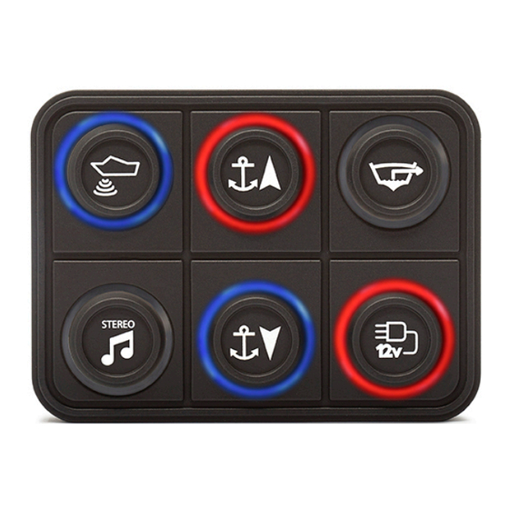
Blue CAN L White CAN H Black Negative battery Red Vbatt. (12-24V) Each end of the CAN bus is terminated with 120Ω resistors in compliance with the standard to minimize signal reflections on the bus. You may need to place a 120Ω resistor between CAN-L and CAN-H. 2. Reference Front view. PKP-2300-SI-FR Via Montefeltro, 6 – 20156 Milano (MI) – Italy - 4 - Tel. +39 (02) 3088583 – Fax +39 (02) 33406697 PKP-2300-SI-FR_CANopenUM_REV1.3 www.blinkmarine.com – info@blinkgroup.com... -
Page 5: Default Settings
3. Default settings Setting Default state or level How to change Baud Rate 125 kbit/s Object 2010h CANopen Node ID 15h Object 2013h Device active on Not active Object 2012h startup Key Brightness 3Fh (Maximum Brightness) Object 2003h Backlight Brightness 00h (OFF) Object 2003h Backlight Color Amber Object 2003h Startup LED Light Show Complete LED Sequence Object 2014h Periodic State Disable Object 1800h Transmission DEMO mode Disable Object 2100h Heartbeat Message Disable Object 1017h Boot-up service Active Object 2011h NMT MESSAGES The Network Management messages follow a master-slave structure. Through NMT services,... -
Page 6: Reset Canopen Node
6. Reset CANopen node Identifier 00h Byte 0 81h Reset CANopen node Keypad CAN ID Byte 1 XXh 00h: reset all the keypads 15h: reset the keypad with CAN ID = 15h. Byte 2, 7 00h Not used Example: Direction Identifier Format Message To Keypad Std 81 15 7. Stop CANopen node Identifier 00h Byte 0 XXh 02h: Stop CANopen node 00h: Stop CANopen node (old PKP sw compatibility) Byte 1 YYh Keypad CAN ID 00h: stop all the keypads 15h: stop the keypad with CAN ID = 15h. -
Page 7: Heartbeat Message
9. Heartbeat message The heartbeat mechanism for a CANopen device is established by cyclically transmitting the heartbeat message by the heartbeat producer. Refer to Object 1017h for more details. PDO messages PDO (Process Data Object) are fast telegram messages that can simply manage most important functions. There are no answers for this kind of messages. Each PDO message has an equivalent Service Data Object message. 10. Keys state message The keypad must be activated, see NMT Start CANopen Node message. PKP-2300-SI-FR • Identifier 180 + current CAN ID Default 195h Byte 0 Keys from #1 to #4 Keys: 1=pressed; 0=released 0 0 K6 K5 - K4 K3 K2 K1 Byte 1, 3 00h Not used Byte 4 XXh Tick Timer Examples: Direction Identifier Format Message Key state From Keypad 195... -
Page 8: Set Led On Message
11. Set LED ON message The keypad must be activated, see NMT Start CANopen Node message. PKP-2300-SI-FR • Identifier 200 + current CAN ID Default 215h Byte 0 0 0 R6 R5 - R4 R3 R2 R1 Red LED Byte 1 0 0 G6 G5 - G4 G3 G2 G1 Green LED Byte 2 0 0 B6 B5 - B4 B3 B2 B1 Blue LED Byte 2,7 00h Not used Examples: Direction Identifier Format Message LED To Keypad 215 Std 00 00 00 00 00 00 00 00 Turn OFF all the LED To Keypad 215 Std 01 00 00 00 00 00 00 00 Only red LED #1 ON To Keypad... -
Page 9: Set Led Blink Message
12. Set LED Blink message The keypad must be activated, see NMT Start CANopen Node message. Note: if the blink message is sent when the LED is already ON, the LED blinks in alternative mode. PKP-2300-SI-FR • Identifier 300 + current CAN ID Default 315h Byte 0 0 0 R6 R5 - R4 R3 R2 R1 Red LED Byte 1 0 0 G6 G5 - G4 G3 G2 G1 Green LED Byte 2 0 0 B6 B5 - B4 B3 B2 B1 Blue LED Byte 2,7 00h Not used Examples: Direction Identifier Format Message LED To Keypad 315 Std 00 00 00 00 00 00 00 00 Turn OFF all the LED To Keypad 315 Std 01 00 00 00 00 00 00 00 Only red LED #1 blinks... -
Page 10: Backlight Brightness Level
515 Std 00 00 00 00 00 00 00 00 Turn off the backlight To Keypad 515 Std 10 00 00 00 00 00 00 00 Backlight brightness = 25% SDO Messages: A SDO (Service Data Object) is providing direct access to object entries of a CANopen device's object dictionary. 15. Object 2000h: Digital input module, keys states This module contains all the Switch State information. A one indicates the switch is pressed, a zero indicates the switch is released. PKP-2300-SI-FR • Identifier 600h + current CAN ID Default 615h Byte 0 40h Read Device Register Byte 1 00h CAN Object 2000h Byte 2 20h Byte 3 01h Sub index... -
Page 11: Object 2001H: Digital Output Module
16. Object 2001h: Digital output module. This module sets and reads the LED Outputs States. Each bit position represents the corresponding LED. A one indicates the LED is ON a zero indicates the LED is OFF. a) Set LED ON PKP-2300-SI-FR • Identifier 600h + current CAN ID Default 615h Byte 0 2Fh Set Device Register Byte 1 01h CAN Object 2001h Byte 2 20h Byte 3 XXh XX: Sub index 01h: Red Led 02h: Green Led 03h: Blue Led Byte 4 YYh 0 0 L6 L5 L4 L3 L2 L1 LED position Byte 5,7 00h Not used ì Examples:... -
Page 12: A) Set Led Blink
17. Object 2002h: Digital output module. This module sets and reads the LED Blink States. Each bit position represents the corresponding LED. A one indicates the LED is blinking a zero indicates the LED is not blinking. If the blink message is sent when the LED is already ON, the LED blinks in alternative mode. a) Set LED blink • PKP-2300-SI-FR Identifier 600h + current CAN ID Default 615h Byte 0 2Fh Set Device Register Byte 1 02h CAN Object 2002h Byte 2 20h Byte 3 XXh XX: Sub index 01h: Red Led 02h: Green Led 03h: Blue Led Byte 4 YYh 0 0 L6 L5 L4 L3 L2 L1 LED position Byte 5,7 00h Not used Examples:... -
Page 13: Object 2003: Brightness Level
18. Object 2003: Brightness Level a) Set Indicator LED brightness level Identifier 615h (600h + current CAN ID) Byte 0 2Fh Set Device Register Byte 1 03h CAN Object 2003h Byte 2 20h Byte 3 01h Sub index Byte 4 YYh Intensity 00h-3Fhà min-100% Byte 5,7 00h Not used Example: Direction Identifier Format Message Data To Keypad 615 Std 2F 03 20 01 10 00 00 00 Brightness = 25% Keypad Reply 595 Std... -
Page 14: C) Backlight Color
c) Backlight color Identifier 615h (600h + current CAN ID) Byte 0 2Fh Set Device Register Byte 1 03h CAN Object 2003h Byte 2 20h Byte 3 03h Sub index Byte 4 XXh Color 01h: red 02h: green 03h: blue 04h: yellow 05h: cyan 06h: violet 07h: white/light blue 08h: amber/orange 09h: yellow/green Byte 5,7 00h Not used Example: Direction Identifier Format Message Data To Keypad 615 Std 2F 03 20 03 01 00 00 00 Red Backlight color Keypad Reply 595... -
Page 15: E) Set Startup Indicator Led Brightness Level
e) Set startup Indicator LED brightness level Identifier 615h (600h + current CAN ID) Byte 0 2Fh Set Device Register Byte 1 03h CAN Object 2003h Byte 2 20h Byte 3 05h Sub index Byte 4 XXh Intensity 00h-3Fhà min-100% Byte 5,7 00h Not used Example: Direction Identifier Format Message Data To Keypad 615 Std 2F 03 20 05 10 00 00 00 Brightness = 25% Keypad Reply 595 Std 60 03 20 05 00 00 00 00 f) Set startup backlight brightness level Identifier... -
Page 16: Object 2011H: Set Boot-Up Service
20. Object 2011h: Set Boot-up service Object 2011h message enable or disable the boot up message sent by the keypad at power up to the CAN network. Identifier 600h + current CAN ID Default 615h Byte 0 2Fh Set Device Register Byte 1 11h CAN Object 2011h Byte 2 20h Byte 3 00h Sub index Byte 4 XXh 00h: Not active 01h: Active Byte 5,7 00h Not used Example: Direction Identifier Format Message Data To Keypad 615 Std 2F 11 20 00 00 00 00 00 Boot-up service not active Keypad Reply 595 Std 60 11 20 00 00 00 00 00... -
Page 17: Object 2014H: Set Startup Led Show
23. Object 2014h: Set startup LED show Identifier 600h + current CAN ID Default 615h Byte 0 2Fh Set Device Register Byte 1 14h CAN Object 2014h Byte 2 20h Byte 3 00h Sub index Byte 4 XXh 00h: Disable 01h: Complete LED Show (default) 02h: Fast Flash Byte 5,7 00h Not used Example: Direction Identifier Format Message Data To Keypad 615 Std 2F 14 20 00 00 00 00 00 Disable startup LED show Keypad Reply 595 Std... -
Page 18: Object 1017H: Producer Heartbeat Time
25. Object 1017h: Producer heartbeat time The producer heartbeat time shall indicate the configured cycle time of the heartbeat. Identifier 600h + current CAN ID Default 615h Byte 0 40h Read Device Register Set device register Byte 1 17h CAN Object 1017h Byte 2 10h Byte 3 00h Sub index Byte 4 YYh YYh: Heartbeat time in milliseconds MSByte Byte 5 XXh XXh: Heartbeat time in milliseconds LSByte Byte 5, 7 00h Not used Heartbeat time: XXYYh (from 000Ah to FFFEh: 10ms to 65534 ms) Examples: Direction Identifier Format Message Data To Keypad 615 Std 40 17 10 00 00 00 00 00 Read heartbeat time... -
Page 19: Object 1000H: Device Type
Direction Identifier Format Message Data From Keypad 715h Std 00h Boot up From Keypad 715h Std 7Fh Pre-operational To keypad 00h Std 01h 15h Start keypad with CAN ID 15h From Keypad 715h Std 05h Operational 26. Object 1000h: Device Type Identifier 600h + current CAN ID Default 615h Byte 0 40h Read Device Register Byte 1 00h CAN Object 1000h Byte 2 10h Byte 3, 7 00h... -
Page 20: Object 1009H: Manufacturer Hardware Revision
Example: Direction Identifier Format Message Data To Keypad 615 Std 40 08 10 00 00 00 00 00 Keypad Reply 595 Std 41 08 10 00 0B 00 00 00 To Keypad 615 Std 60 00 00 00 00 00 00 00 Keypad Reply 595 Std 00 42 6C 69 6E 6B 4D 61 BlinkMa To Keypad 615 Std 70 00 00 00 00 00 00 00 Keypad Reply 595 Std 17 72 69 6E 65 00 00 00 rine Manufacturer Device Name: BlinkMarine The first byte of the last data message replied is 17h. 29. Object 1009h: Manufacturer Hardware Revision Identifier 600h + current CAN ID Default 615h... -
Page 21: Object 100Bh: Model
31. Object 100Bh: Model ID Identifier 600h + current CAN ID Default 615h Byte 0 40h Read Device Register Byte 1 0Bh CAN Object 100Bh Byte 2 10h Byte 3, 7 00h Not used 1° additional byte Identifier 600h + current CAN ID Default 615h Byte 0 60h Read Device Register second byte Byte 1, 7 00h Not used 2° additional byte Identifier 600h + current CAN ID Default 615h Byte 0 70h Read Device Register third byte Byte 1, 7 00h Not used Example: Direction Identifier Format Message... -
Page 22: Object 1018H: Identity Data
32. Object 1018h: Identity Data Identifier 615h (600h + current CAN ID) Byte 0 40h Read Device Register Byte 1 18h CAN Object 1018h Byte 2 10h Byte 3 00h Number of mapped objects 01h Vendor Id 04h Serial number Byte 4,7 00h Not used Examples: Direction Identifier Format Message Data To Keypad 615 Std 40 18 10 00 00 00 00 00 Keypad Reply 595 Std 4F 18 10 00 04 00 00 00 To Keypad 615 Std 40 18 10 01 00 00 00 00... -
Page 23: Object 1401H: Receive Pdo Communication Parm 1
34. Object 1401h: Receive PDO communication Parm 1 Describes the Receive Parameters for the LED blink PDO Message. Identifier 615h (600h + current CAN ID) Byte 0 40h Read Device Register Byte 1 01h CAN Object 1401h Byte 2 14h 00h Number of mapped objects Byte 3 01h COB Id 02h Transmission Type Byte 4,7 00h Not used Examples: Direction Identifier Format Message Data To Keypad 615 Std 40 01 14 00 00 00 00 00 Keypad Reply 595 Std 4F 01 14 00 02 00 00 00... -
Page 24: Object 1403H: Receive Pdo Communication Parm 3
36. Object 1403h: Receive PDO communication Parm 3 Describes the Receive Parameters for backlight LED brightness Identifier 615h (600h + current CAN ID) Byte 0 40h Read Device Register Byte 1 03h CAN Object 1403h Byte 2 14h 00h Highest sub-index supported 01h COB Id Byte 3 02h Transmission Type Byte 4,7 00h Not used Examples: Direction Identifier Format Message Data To Keypad 615 Std 40 03 14 00 00 00 00 00 Keypad Reply 595 Std 4F 03 14 00 02 00 00 00... -
Page 25: Object 1600H: Receive Pdo Mapping Parameter 0
37. Object 1600h: Receive PDO mapping Parameter 0 Describes the mapping of LED state PDO Message. Identifier 615h (600h + current CAN ID) Byte 0 40h Read Device Register Byte 1 00h CAN Object 1600h Byte 2 16h Byte 3 00h Number of mapped objects 01h PDO Mapping Entry 1 02h PDO Mapping Entry 2 03h PDO Mapping Entry 3 Byte 4,7 00h Not used Examples: Direction Identifier Format Message Data To Keypad 615 Std 40 00 16 00 00 00 00 00 Keypad Reply 595... -
Page 26: Object 1601H: Receive Pdo Mapping Parameter 1
38. Object 1601h: Receive PDO mapping Parameter 1 Describes the mapping of LED blink state PDO Message. Identifier 615h (600h + current CAN ID) Byte 0 40h Read Device Register Byte 1 01h CAN Object 1601h Byte 2 16h Byte 3 00h Number of mapped objects 01h PDO Mapping Entry 1 02h PDO Mapping Entry 2 03h PDO Mapping Entry 3 Byte 4,7 00h Not used Examples: Direction Identifier Format Message Data To Keypad 615 Std 40 00 16 00 00 00 00 00 Keypad Reply 595... -
Page 27: Object 1603H: Receive Pdo Mapping Parameter 3
40. Object 1603h: Receive PDO mapping Parameter 3 Describes the mapping of backlight brightness PDO Message. Identifier 615h (600h + current CAN ID) Byte 0 40h Read Device Register Byte 1 03h CAN Object 1601h Byte 2 16h Byte 3 00h Number of mapped objects 01h PDO Mapping Entry 1 Byte 4,7 00h Not used Examples: Direction Identifier Format Message Data To Keypad 615 Std 40 03 16 00 00 00 00 00 Keypad Reply 595 Std 4F 03 16 00 01 00 00 00 To Keypad 615... - Page 28 b) Set periodic state transmission Identifier 600h + current CAN ID Default 615h Byte 0 2Bh Set device register Byte 1 00h CAN Object 1800h Byte 2 18h Byte 3 05h Sub index Byte 4 YYh YYh: Event timer period in milliseconds Byte 5 XXh XXh: Event timer period in milliseconds Byte 5, 7 00h Not used Event timer period: XXYYh (from 000Ah to FFFEh: 10ms to 65534 milliseconds). Examples: Direction Identifier Format Message Data To Keypad 615 Std 2B 00 18 00 00 00 00 00 Switch off the periodic state transmission Keypad Reply 595...
- Page 29 43. Object 2200h: Serial number string Identifier 600h + current CAN ID Default 615h Byte 0 40h Read Device Register Byte 1 00h CAN Object 2200h Byte 2 22h Byte 3,7 00h Not used 1° additional byte Identifier 600h + current CAN ID Default 615h Byte 0 60h Read Device Register second byte Byte 1, 7 00h Not used 2° additional byte Identifier 600h + current CAN ID Default 615h Byte 0 70h Read Device Register third byte Byte 1, 7 00h Not used Example: Direction Identifier...
-
Page 30: Appendix: Demo Mode Instructions
APPENDIX: DEMO Mode instructions In DEMO Mode you can try the following functions by pressing buttons on the PKP2300. Entering this mode, you turn on backlight red; for the key 1 each time you press the button you can change the color of backlight with this sequence: Red; Green; Blue; Yellow; Cyan; Magenta; White/light blue; Amber; Yellow/green; 10. OFF. For the key 4, each time that you press the button, there are different steps in this sequence: 1. Complete LED show of all colors; 2. Backlight active with keys on in sequence (it is possible to change the color of LED keys pressing button 1) 3. Alternate blinking of LED keys number 1 with red color; 2 with amber color; 3 with yellow; 4 with green color; 5 with cyan color and 6 with white/light blue color. Via Montefeltro, 6 – 20156 Milano (MI) – Italy - 30 - Tel. -
Page 31: Revision History
45. Revision History Manual Related SW Date Comment version Revision 27/05/2016 1.0 First Release 1.4 25/07/2016 1.1 Updated wrong paragraphs numbering 1.4 21/11/2016 1.2 Added PDO 400h and 500h, added heartbeat state 1.4 04: stop. 29/01/2018 Added objects 1402h,1403h,1602h,1603h • Corrected minimum value for Indicator LEDs • brightness Corrected limit values for heartbeat and periodic •...
Need help?
Do you have a question about the PKP-2300-SI-FR and is the answer not in the manual?
Questions and answers