Table of Contents
Advertisement
THE PRESENT MANUAL IS FOR REFERENCE ONLY AND MIGHT BE NOT UP TO DATE TO THE LATEST VERSION.
Via Montefeltro, 6 – 20156 Milano (MI) – Italy
Tel. +39 (02) 3088583 – Fax +39 (02) 33406697
www.blinkmarine.com – info@blinkgroup.com
PKP-2400-LI
CANOPEN USER MANUAL
PLEASE CONTACT US FOR GETTING THE MOST UPDATED FILE
PKP-2400-LI_CANopen_UM_REV1.1
Advertisement
Table of Contents

Related Manuals for Blink Marine PKP-2400-LI


Summary of Contents for Blink Marine PKP-2400-LI
- Page 1 PKP-2400-LI CANOPEN USER MANUAL THE PRESENT MANUAL IS FOR REFERENCE ONLY AND MIGHT BE NOT UP TO DATE TO THE LATEST VERSION. PLEASE CONTACT US FOR GETTING THE MOST UPDATED FILE Via Montefeltro, 6 – 20156 Milano (MI) – Italy Tel. +39 (02) 3088583 – Fax +39 (02) 33406697 www.blinkmarine.com – info@blinkgroup.com PKP-2400-LI_CANopen_UM_REV1.1...
-
Page 2: Table Of Contents
4. Start CANopen node (keypad activation message) ............. 5 5. Enter pre-operational ....................5 6. Reset CANopen node ....................6 7. Stop CANopen node ....................6 8. Boot-up service ......................6 9. Heartbeat message ...................... 7 PDO messages ......................8 10. Keys status message ....................8 PKP-2200-LI ....................... 8 PKP-2400-LI ....................... 8 11. Set LED ON message ....................9 PKP-2200-LI ....................... 9 PKP-2400-LI ....................... 9 12. Set LED Blink message ....................10 PKP-2200-LI ......................10 PKP-2400-LI ......................10 SDO Messages: ......................11 13. Object 6500h: Command Module ................11 a) Set single LED state: 01h ..................11... - Page 3 PKP-2200-LI ......................17 PKP-2400-LI ......................17 15. Object 6001h: Digital output module. ............... 18 a) Set LED ON ......................... 18 PKP-2200-LI ......................18 PKP-2400-LI ......................18 b) Read LED ON ......................19 PKP-2200-LI ......................19 PKP-2400-LI ......................19 16. Object 6002h: Digital output module. ............... 20 a) Set LED blink ......................20 PKP-2200-LI ......................20 PKP-2400-LI ......................21 b) Read LED blink ......................21 PKU 2200 ......................... 21 PKU 2400 ......................... 22 17. Object 1017h: Producer heartbeat time ..............22 18. Object 1000h: Device Type ..................23 19. Object 1008h: Manufacturer Device Name ............... 23 20. Object 1009h: Manufacturer Hardware Revision .
-
Page 4: How To Connect Deutsch 4 Pin
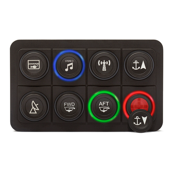
Green CAN L Yellow CAN H Black Negative battery Red Vbatt. (12-24V) Each end of the CAN bus is terminated with 120Ω resistors in compliance with the standard to minimize signal reflections on the bus. You may need to place a 120Ω resistor between CAN-L and CAN-H. 2. Reference Front view. PKP-2400-LI Via Montefeltro, 6 – 20156 Milano (MI) – Italy - 4 - Tel. +39 (02) 3088583 – Fax +39 (02) 33406697 www.blinkmarine.com – info@blinkgroup.com PKP-2400-LI_CANOpen_UM_REV1.1... -
Page 5: Default Settings
3. Default settings Setting Default status or level How to change Baud Rate 125 kbit/s Object 6500h Command 11h CANopen Node ID 15h Object 6500h Command 70h Device active on Not active Object 6500h Command 10h startup Key Brightness 3Fh (Maximum Brightness) Object 6500h Command 02h Backlight Brightness 00h (OFF) Object 6500h Command 03h Backlight Color Amber Object 6500h Command 7Dh Startup LED Light Complete LED Sequence Object 6500h Command 50h Show Periodic Message Disable Object 6500h Command 12h Transmission DEMO mode Disable Object 6500h Command 7Ah Heartbeat Message Disable Object 1017h Boot-up service Active Object 6500h Command 13h NMT MESSAGES... -
Page 6: Reset Canopen Node
6. Reset CANopen node Identifier 00h Byte 0 81h Reset CANopen node Keypad CAN ID Byte 1 XXh 00h: reset all the keypads 15h: reset the keypad with CAN ID = 15h. Byte 2, 7 00h Not used Example: Direction Identifier Format Message To Keypad Std 81 15 7. Stop CANopen node Identifier 00h Byte 0 XXh 02h: Stop CANopen node 00h: Stop CANopen node (old sw compatibility) Byte 1 YYh Keypad CAN ID 00h: stop all the keypads 15h: stop the keypad with CAN ID = 15h. -
Page 7: Heartbeat Message
9. Heartbeat message The heartbeat mechanism for a CANopen device is established by cyclically transmitting the heartbeat message by the heartbeat producer. One or more CANopen devices in the network are aware of this heartbeat message. If the heartbeat cycle fails for the heartbeat producer, the local application on the heartbeat consumer will be informed about that event. If a CANopen device starts with a value for the heartbeat producer time unequal to 0 the boot-up message is regarded as first heartbeat message. Identifier 700h + current CAN ID Default 715h XXh: State of heartbeat producer Byte 0 XXh 00h: Boot-up 05h: Operational 7Fh: Pre-operational Example: Direction Identifier Format Message Data From Keypad 715h Std 00h Boot up From Keypad 715h Std 7Fh Pre-operational To keypad 00h Std 01h 15h Start keypad with CAN id =15h From Keypad 715h Std... -
Page 8: Pdo Messages
PDO messages PDO (Process Data Object) are fast telegram messages that can simply manage most important functions. There are no answers for this kind of messages. Each PDO message has an equivalent Service Data Object message. 10. Keys status message The keypad must be activated, see NMT Start CANopen Node message. PKP-2200-LI • Identifier 180 + current CAN ID Default 195h Byte 0 Keys from #1 to #4 Keys: 1=on; 0=off 0 0 0 0 - K4 K3 K2 K1 Byte 1, 3 00h Not used Byte 4 XXh Tick Timer Examples: Direction Identifier Format Message Key state From Keypad 195 Std 00 00 00 00 XX No key pressed From Keypad 195 Std 04 00 00 00 XX Key #3 pressed From Keypad 195... -
Page 9: Pkp-2400-Li
To Keypad 215 Std 80 00 00 00 00 00 00 00 Only green LED #4 on To Keypad 215 Std 00 01 00 00 00 00 00 00 Only blue LED #1 on To Keypad 215 Std 77 00 00 00 00 00 00 00 Amber LED #1, 2, 3 on To Keypad 215 Std 33 03 00 00 00 00 00 00 White LED #1, 2 on PKP-2400-LI • Identifier 200 + current CAN ID Default 215h Byte 0 R8 R7 R6 R5 - R4 R3 R2 R1 Red LED Byte 1 G8 G7 G6 G5 - G4 G3 G2 G1 Green LED Byte 2 B8 B7 B6 B5 - B4 B3 B2 B1 Blue LED Byte 3,7 00h Not used Examples: Direction... -
Page 10: Set Led Blink Message
315 Std 0F 0F 00 00 00 00 00 00 All magenta LED blink To keypad 315 Std 11 01 00 00 00 00 00 00 Only white LED #1 blinks To Keypad 215 Std 80 00 00 00 00 00 00 00 Only LED #4 blinks red 315 Std 88 00 00 00 00 00 00 00 and green in alternate mode PKP-2400-LI Identifier 300 + current CAN ID Default 315h Byte 0 R8 R7 R6 R5 - R4 R3 R2 R1 Red LED Byte 1 G8 G7 G6 G5 - G4 G3 G2 G1 Green LED Byte 2 B8 B7 B6 B5 - B4 B3 B2 B1 Blue LED Byte 3,7 00h Not used Examples: Direction Identifier Format Message... -
Page 11: Sdo Messages
SDO Messages: A SDO (Service Data Object) is providing direct access to object entries of a CANopen device's object dictionary. 13. Object 6500h: Command Module a) Set single LED state: 01h Identifier 600h + current CAN ID Default 615h Byte 0 23h Set Device Register Byte 1 00h CAN Object 6500h Byte 2 65h Byte 3 01h Sub index Byte 4 01h Command: Set single LED state Key Number (01-04h) for PKU 2200 Byte 5 XXh Key Number (01-08h) for PKU 2400 Key Number (01-0Ch) for PKU 2600 00h OFF 01h – 03h Red: 01h on; 02h blink; 03h alt blink 04h – 06h Green: 04h on; 05h blink; 06h alt blink... -
Page 12: C) Set Backlight Brightness Level: 03H
Set backlight brightness level: 03h Identifier 600h + current CAN ID Default 615h Byte 0 23h Set Device Register Byte 1 00h CAN Object 6500h Byte 2 65h Byte 3 01h Sub index Byte 4 03h Command: Set backlight brightness Byte 5 XXh Intensity 00h-3Fhà 0 – 100% brightness Byte 6,7 00h Not used Example: Direction Identifier Format Message Data To Keypad 615 Std 23 00 65 01 03 2F 00 00 Backlight brightness = 75% Keypad 595... -
Page 13: E) Set Device Active On Startup: 10H
d) Set device active on startup: 10h If keypad is active on startup don’t need Start command from host Identifier 600h + current CAN ID Default 615h Byte 0 23h Set Device Register Byte 1 00h CAN Object 6500h Byte 2 65h Byte 3 01h Sub index Byte 4 10h Command: Set device active on startup Byte 5 XXh 00h: Not active 01h: Active Byte 6,7 00h Not used Example: Direction Identifier Format Message Data To Keypad 615 Std 23 00 65 01 10 01 00 00 Set device active on... -
Page 14: H) Set Boot-Up Service: 13H
g) Set Boot-up service: 13h Identifier 600h + current CAN ID Default 615h Byte 0 23h Set Device Register Byte 1 00h CAN Object 6500h Byte 2 65h Byte 3 01h Sub index Byte 4 13h Command: Set Boot-up service Byte 5 XXh 00h: Not active 01h: Active Byte 6,7 00h Not used Example: Direction Identifier Format Message Data To Keypad 615 Std 23 00 65 01 13 00 00 00 Set Boot-up service not active Keypad reply 595... -
Page 15: K) Set Default Startup Backlight Level: 7Bh
j) Set default startup backlight level: 7Bh Identifier 600h + current CAN ID Default 615h Byte 0 23h Set Device Register Byte 1 00h CAN Object 6500h Byte 2 65h Byte 3 01h Sub index Byte 4 7Bh Command: Set backlight level Byte 5 XXh 0-3Fh à 0 – 100% brightness Byte 6,7 00h Not used Example: Direction Identifier Format Message Data To Keypad 615 Std 23 00 65 01 7B 00 00 00 Backlight off at startup Keypad reply... -
Page 16: M) Set Demo Mode: 7Ah
l) Set DEMO mode: 7Ah This message enables the Demo mode function. Demo mode is a special feature that consists in different LED states for each button pressing. Refer to the appendix “Demo mode instructions” to try these special features. Disconnect and reconnect the keypad after the enable message to enter this mode. To exit the Demo mode, send the Disable Demo mode command or another command message. Identifier 615h (600h + current CAN ID) Byte 0 23h Set Device Register Byte 1 00h CAN Object 6500h Byte 2 65h Byte 3 01h Sub index Byte 4 7Ah Command: Set DEMO mode Byte 5 XXh 01h: on 00h: off... -
Page 17: Object 6000H: Digital Input Module, Keys States
43 00 60 00 01 00 00 00 Key 1 pressed 43 00 60 00 02 00 00 00 Key 2 pressed Keypad 595 std 43 00 60 00 04 00 00 00 Key 3 pressed reply 43 00 60 00 08 00 00 00 Key 4 pressed 43 00 60 00 03 00 00 00 Key 1 and 2 pressed 43 00 60 00 0A 00 00 00 Key 2 and 4 pressed 43 00 60 00 07 00 00 00 Key 1, 2 and 3 pressed 43 00 60 00 0F 00 00 00 All keys pressed • PKP-2400-LI Identifier 600h + current CAN ID Default 615h Byte 0 40h Read Device Register Byte 1 00h CAN Object 6000h Byte 2 60h Byte 3 00h Sub index Byte 4,7 00h Not used Examples:... -
Page 18: Object 6001H: Digital Output Module
Std 60 01 60 00 00 00 00 00 To Keypad 615 Std 23 01 60 00 80 00 00 00 Set green LED #4 ON Keypad reply 595 Std 60 01 60 00 00 00 00 00 To Keypad 615 Std 23 01 60 00 04 00 00 00 Set red LED #3 ON Keypad reply 595 Std 60 01 60 00 00 00 00 00 • PKP-2400-LI Identifier 600h + current CAN ID Default 615h Byte 0 23h Set Device Register Byte 1 01h CAN Object 6001h Byte 2 60h Byte 3 00h Sub index Byte 4 XXh R8 R7 R6 R5 R4 R3 R2 R1 Red LED Byte 5... -
Page 19: B) Read Led On
Green LED #2 To Keypad 615 Std 40 01 60 00 00 00 00 00 Keypad reply 595 Std 43 01 60 00 F0 00 00 00 All green LED To Keypad 615 Std 40 01 60 00 00 00 00 00 Keypad reply 595 Std 43 01 60 00 00 0F 00 00 All blue LED ON • PKP-2400-LI Identifier 600h + current CAN ID Default 615h Byte 0 40h Read Device Register Byte 1 01h CAN Object 6001h Byte 2 60h Byte 3 00h Sub index Byte 4,7 00h Not Used Examples: Direction... -
Page 20: Object 6002H: Digital Output Module
16. Object 6002h: Digital output module. This module sets and reads the LED Blink States. Each bit position represents the corresponding LED. A one indicates the LED is blinking, a zero indicates the LED is normal. If the blink bit is active with the ON bit active, the LED will blink inverse to normal operation (ALT blink). a) Set LED blink • PKP-2200-LI Identifier 600h + current CAN ID Default 615h Byte 0 23h Set Device Register Byte 1 02h CAN Object 6002h Byte 2 60h Byte 3 00h Sub index Byte 4 XYh X: G4 G3 G2 G1 Green LED Y: R4 R3 R2 R1 Red LED Byte 5 0Zh Z: B4 B3 B2 B1 Blue LED Byte 6,7 00h Not used Examples: Direction Identifier... -
Page 21: Pkp-2400-Li
• PKP-2400-LI Identifier 600h + current CAN ID Default 615h Byte 0 23h Set Device Register Byte 1 02h CAN Object 6002h Byte 2 60h Byte 3 00h Sub index Byte 4 XXh R8 R7 R6 R5 R4 R3 R2 R1 Red LED Byte 5 YYh G8 G7 G6 G5 G4 G3 G2 G1 Green LED Byte 6 ZZh B8 B7 B6 B5 B4 B3 B2 B1 Blue LED Byte 7 00h Not used Examples: Direction Identifier Format Message Data To Keypad 615 Std 23 02 60 00 00 00 00 00 No LED blinks Keypad reply... -
Page 22: Pku 2400
• PKP-2400-LI Identifier 600h + current CAN ID Default 615h Byte 0 40h Read Device Register Byte 1 02h CAN Object 6002h Byte 2 60h Byte 3 00h Sub index Byte 4,7 00h Not Used Examples: Direction Identifier Format Message Data To Keypad 615 Std 40 02 60 00 00 00 00 00 Keypad reply 595 Std 43 02 60 00 FF 00 00 00 Only red LED blink To Keypad 615 Std 40 02 60 00 00 00 00 00 Keypad reply 595... -
Page 23: Object 1000H: Device Type
18. Object 1000h: Device Type Identifier 600h + current CAN ID Default 615h Byte 0 40h Read Device Register Byte 1 00h CAN Object 1000h Byte 2 10h Byte 3, 7 00h Not used Example: Direction Identifier Format Data To Keypad 615 Std 40 00 10 00 00 00 00 00 Keypad reply 595 Std 43 00 10 00 91 01 03 00 Device profile number 30191h. 19. Object 1008h: Manufacturer Device Name Identifier 600h + current CAN ID Default 615h Byte 0 40h... -
Page 24: Object 1009H: Manufacturer Hardware Revision
20. Object 1009h: Manufacturer Hardware Revision Identifier 600h + current CAN ID Default 615h Byte 0 40h Read Device Register Byte 1 09h CAN Object 1009h Byte 2 10h Byte 3, 7 00h Not used 1° additional byte Identifier 600h + current CAN ID Default 615h Byte 0 60h Read Device Register second byte Byte 1, 7 00h Not used 2° additional byte Identifier 600h + current CAN ID Default 615h Byte 0 70h Read Device Register third byte Byte 1, 7 00h Not used Example: Direction Identifier... -
Page 25: Object 100Ah: Manufacturer Firmware Revision
21. Object 100Ah: Manufacturer Firmware Revision Identifier 600h + current CAN ID Default 615h Byte 0 40h Read Device Register Byte 1 0Ah CAN Object 100Ah Byte 2 10h Byte 3, 7 00h Not used 1° additional byte Identifier 600h + current CAN ID Default 615h Byte 0 60h Read Device Register second byte Byte 1, 7 00h Not used 2° additional byte Identifier 600h + current CAN ID Default 615h Byte 0 70h Read Device Register third byte Byte 1, 7 00h Not used Example: Direction Identifier... -
Page 26: Object 1018H: Identity Data
Direction Identifier Format Message Data To Keypad 615 Std 40 0B 10 00 00 00 00 00 Keypad reply 595 Std 41 0B 10 00 07 00 00 00 To Keypad 615 Std 60 00 00 00 00 00 00 00 Keypad reply 595 Std 00 50 4B 55 32 34 30 30 PKU2400 To Keypad 615 Std 70 00 00 00 00 00 00 00 Keypad reply 595 Std 1D 00 00 00 00 00 00 00 Model ID: PKU2400 23. Object 1018h: Identity Data 1. Number of mapped objects Identifier 600h + current CAN ID Default 615h... - Page 27 3. Product code Identifier 600h + current CAN ID Default 615h Byte 0 40h Read Device Register Byte 1 18h CAN Object 1018h Byte 2 10h Byte 3 02h Sub index Byte 4,7 00h Not used Example: Direction Identifier Format Message Data To Keypad 615 Std 40 18 10 02 00 00 00 00 Keypad reply 595 Std 43 18 10 02 00 00 00 00 00h Product code: 0h Revision Number Identifier 600h + current CAN ID Default 615h Byte 0 40h...
-
Page 28: Object 1400H: Receive Pdo Communication Parm 0
24. Object 1400h: Receive PDO Communication Parm 0 Describes the receive parameters for the LED States PDO message. Identifier 600h + current CAN ID Default 615h Byte 0 40h Read Device Register Byte 1 00h CAN Object 1400h Byte 2 14h 00h: Number of mapped objects Byte 3 XXh 01h: COB Id 03h: Inhibit Time Byte 4,7 00h Not used Example: Direction Identifier Format Message Data To Keypad 615 Std 40 00 14 00 00 00 00 00 Keypad reply 595 Std 4F 00 14 00 02 00 00 00 To Keypad... -
Page 29: Object 1600H: Output Descriptions
26. Object 1600h: Output Descriptions Receives asynchronously digital outputs mapping Identifier 600h + current CAN ID Default 615h Byte 0 40h Read Device Register Byte 1 00h CAN Object 1600h Byte 2 16h 00h: Number of mapped objects Byte 3 XXh 01h: Set LED outputs 02h: Set LED blink Byte 4,7 00h Not used Example: Direction Identifier Format Message Data To Keypad 615 Std 40 00 16 00 00 00 00 00 Keypad reply 595 Std 4F 00 16 00 02 00 00 00 To Keypad 615 Std 40 00 16 01 00 00 00 00... -
Page 30: Object 1800H: Transmit Pdo Communication Parm 0
27. Object 1800h: Transmit PDO Communication Parm 0 Describes the transmit parameters for the key states PDO message. Identifier 600h + current CAN ID Default 615h Byte 0 40h Read Device Register Byte 1 00h CAN Object 1800h Byte 2 18h 00h: Number of mapped objects 01h: Address base 02h: Transmission Type Byte 3 XXh (asynchronous RTR only). 03h: Inhibit Time 05h: Event Timer/ Writeable Int Value (ms) Byte 4,7 00h Not used Example Direction Identifier Format Message Data To Keypad 615 Std 40 00 18 00 00 00 00 00 Keypad reply... -
Page 31: Object 1A00H: Inputs Description
28. Object 1A00h: Inputs description Identifier 600h + current CAN ID Default 615h Byte 0 40h Read Device Register Byte 1 00h CAN Object 1A00h Byte 2 1Ah Byte 3 XXh 00h: Number of mapped objects 01h: Switch state Byte 4,7 00h Not used Example: Direction Identifier Format Message Data To Keypad 615 Std 40 00 1A 00 00 00 00 00 Keypad reply 595 Std 4F 00 1A 00 01 00 00 00 To Keypad 615 Std 40 00 1A 01 00 00 00 00 Keypad reply 595... -
Page 32: Object 6100H: Device Firmware Specifications
29. Object 6100h: Device firmware specifications This object reads the device firmware specifications. This includes the stored serial Number and the device generic model identification. Identifier 600h + current CAN ID Default 615h Byte 0 40h Read Device Register Byte 1 00h CAN Object 6100h Byte 2 61h 00h: Number of mapped objects Byte 3 XXh 01h: Serial number 02h: Device model ID (2 additional bytes) Byte 4,7 00h Not used Examples: Direction Identifier Format Message Data To Keypad 615 Std 40 00 61 00 00 00 00 00 Keypad reply 595 Std 4F 00 61 00 02 00 00 00 To Keypad... -
Page 33: Object 6201: Device Brightness Control
30. Object 6201: Device brightness control This Object Sets/Reads the device brightness levels of both the key LEDs and the backlight level. Read brightness level Identifier 600h + current CAN ID Default 615h Byte 0 40h Read Device Register Byte 1 01h CAN Object 6201h Byte 2 62h 00h: Number of mapped objects Byte 3 XXh 01h: key-LED brightness level 02h: backlight brightness level Byte 4,7 00h Not used Example: Direction Identifier Format Message Data To Keypad 615 Std 40 01 62 01 00 00 00 00 Keypad reply 595 Std... -
Page 34: Object 6300H: Serial Number String
31. Object 6300h: Serial number string Identifier 600h + current CAN ID Default 615h Byte 0 40h Read Device Register Byte 1 00h CAN Object 6300h Byte 2 63h Byte 3,7 00h Not used 1° additional byte Identifier 600h + current CAN ID Default 615h Byte 0 60h Read Device Register second byte Byte 1, 7 00h Not used 2° additional byte Identifier 600h + current CAN ID Default 615h Byte 0 70h Read Device Register third byte Byte 1, 7 00h Not used Example: Direction Identifier... -
Page 35: Object 6302H: Device Key And Led Count
Object 6302h: Device key and LED count Identifier 600h + current CAN ID Default 615h Byte 0 40h Read Device Register Byte 1 02h CAN Object 6302h Byte 2 63h 00h: Number of objects 01h: Total number of keys Byte 3 XXh 02h: Number of external keys 03h: Total number of LED 04h: Number of external LED Byte 4,7 00h Not used Example: Direction Identifier Format Message Data To Keypad 615 Std 40 02 63 00 00 00 00 00 Keypad reply 595 Std 4F 02 63 00 02 00 00 00 To Keypad... -
Page 36: Appendix: Demo Mode Instructions
APPENDIX: DEMO Mode instructions In DEMO Mode you can try the following functions by pressing buttons on the PKU2200/2400/2600. Entering this mode, you turn on backlight red; for the key 1 each time you press the button you can change the color of backlight with this sequence: Red; Green; Blue; Yellow; Cyan; Magenta; White; Amber; Yellow/green; Revision History Related Manual Date Comment Revision version xx/xx/xxxx 1.0 First release x.x 09/02/2018 1.1 Second release: X.x Updated user’s manual with the • command objects concerning the model PKU2600 Added DEMO MODE instructions • Via Montefeltro, 6 – 20156 Milano (MI) – Italy - 36 - Tel.
Need help?
Do you have a question about the PKP-2400-LI and is the answer not in the manual?
Questions and answers