Table of Contents
Advertisement
Quick Links
Advertisement
Table of Contents

Related Manuals for Qsan Technology XCubeFAS 2026


Summary of Contents for Qsan Technology XCubeFAS 2026
- Page 1 XCubeFAS 2026 Hardware Manual September 2021...
- Page 2 NNOUNCEMENT Copyright © Copyright 2021 QSAN Technology, Inc. All rights reserved. No part of this document may be reproduced or transmitted without written permission from QSAN Technology, Inc. QSAN believes the information in this publication is accurate as of its publication date. The information is subject to change without notice.
-
Page 3: Table Of Contents
Cache-to-Flash Memory Protection ................16 2.6. (Optional) Host Cards ....................20 Installing the System Hardware..................28 3.1. Installation Checklist ..................... 28 3.2. Installing Disk Drives into the Trays ................29 Announcement Official Document © 2021 QSAN Technology, Inc. All rights reserved. www.qsan.com... -
Page 4: Announcement
Getting Technical Support .................... 73 6.2. Online Customer Support ..................... 75 6.3. Accessing Product Updates ..................79 6.4. Documentation Feedback..................... 80 Appendix ..........................81 End-User License Agreement (EULA) ..................81 Announcement Official Document © 2021 QSAN Technology, Inc. All rights reserved. www.qsan.com... - Page 5 Unlock and Open the Carrier Handle of a Disk Drive Tray (SFF) ......... 31 Figure 3-3 Hold the Carrier Handle and Pull out the Disk Drive Tray (SFF) ........31 Announcement Official Document © 2021 QSAN Technology, Inc. All rights reserved. www.qsan.com...
- Page 6 Figure 4-14 Fan Module Installed Successfully ................53 Figure 4-15 Pressing Attention Button of the Flash Module ............55 Figure 4-16 Dummy Cage Screw Location of Cache-to-Flash Module ........... 55 Announcement Official Document © 2021 QSAN Technology, Inc. All rights reserved. www.qsan.com...
- Page 7 Connect the Console Cable ..................75 Figure 6-4 The Procedures of Setup Serial Console by HyperTerminal ........77 Figure 6-5 The Procedures of Setup Serial Console by PuTTY ............79 Announcement Official Document © 2021 QSAN Technology, Inc. All rights reserved. www.qsan.com...
- Page 8 Front Side Components of SFF Disk Drive Trays ............30 Table 4-1 Mechanical Components of the Controller Module ............. 44 Table 4-2 Optional Memory Module Installation Sequence ............48 Announcement Official Document © 2021 QSAN Technology, Inc. All rights reserved. www.qsan.com...
- Page 9 Mechanical Components of the PSU ................50 Table 4-4 Mechanical Components of the Fan Module ............... 53 Table 5-1 Deployment Types ......................62 Table 5-2 System and Expansion Enclosure Configuration Rules ..........63 Announcement Official viii Document © 2021 QSAN Technology, Inc. All rights reserved. www.qsan.com...
-
Page 10: Notices
All of these names are fictitious and any similarity to the names and addresses used by an actual business enterprise is entirely coincidental. Notices Official Document © 2021 QSAN Technology, Inc. All rights reserved. www.qsan.com... -
Page 11: Regulatory Statements
Standards and Specifications listed below. Technical Standard: EMC DIRECTIVE 2014/30/EU (EN55032 / EN55035) UL Statement Rack Mount Instructions - The following or similar rack-mount instructions are included with the installation instructions: Regulatory Statements Official Document © 2021 QSAN Technology, Inc. All rights reserved. www.qsan.com... - Page 12 Recommended operation temperature: 0 ~ 35℃ (31.99 ~ 95°F); operation rating (100-127 Vac, 50-60Hz, 10.0A; 200-240 Vac, 50-60Hz, 5.0A) Regulatory Statements Official Document © 2021 QSAN Technology, Inc. All rights reserved. www.qsan.com...
- Page 13 Las baterias pueden explotar si no se manipulan de forma apropiada. No desmonte ni tire las baterias al fuego. Siga las normativas locales al desechar las baterias agotadas. 警告: (Simplified Chinese) 电池如果更换不正确会有爆炸的危险,请依制造商说明处理用过之电 池。 警告: (Traditional Chinese) 電池如果更換不正確會有爆炸的危險,請依製造商說明處理用過之電 池。 Regulatory Statements Official Document © 2021 QSAN Technology, Inc. All rights reserved. www.qsan.com...
- Page 14 The system may have one or more power supply unit (PSU) cords. To avoid serious injuries, it is recommended that all PSU power cords must be disconnected by trained service technicians before installing or replacing system components. Regulatory Statements Official xiii Document © 2021 QSAN Technology, Inc. All rights reserved. www.qsan.com...
- Page 15 Battery Backup Module or super capacitor module (applies for cache-to- flash module): 1-year limited warranty from date of original purchase. For more detail warranty policy, please refer to QSAN official web site: https://www.qsan.com/warranty Regulatory Statements Official Document © 2021 QSAN Technology, Inc. All rights reserved. www.qsan.com...
-
Page 16: Preface
There are related documents which can be downloaded from the website. XCubeFAS QIG (Quick Installation Guide) XCubeFAS Hardware Manual XCubeFAS XEVO Software Manual Compatibility Matrix White Papers Application Notes Preface Official Document © 2021 QSAN Technology, Inc. All rights reserved. www.qsan.com... -
Page 17: Technical Support
INFORMATION provides useful knowledge, definition, or terminology for reference. TIP provides helpful suggestions for performing tasks more effectively. CAUTION CAUTION indicates that failure to take a specified action could result in damage to the system. Preface Official Document © 2021 QSAN Technology, Inc. All rights reserved. www.qsan.com... -
Page 18: Conventions
Indicates that you have a choice between two or more options | vertical bar or arguments. / Slash Indicates all options or arguments. Indicates the default value. underline Example: [ a | b ] Preface Official xvii Document © 2021 QSAN Technology, Inc. All rights reserved. www.qsan.com... -
Page 19: Product Overview
RODUCT VERVIEW Thank you for purchasing QSAN Technology, Inc. products. XCubeFAS is the leading entry-level flash storage array developed to allow all enterprises to easily enter the era of flash storage. It offers native flash architecture with the exclusive optimization for solid state drive storage, and delivers the best flash data experience of the next generation. -
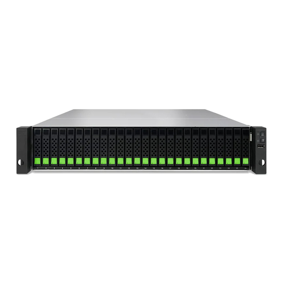
Page 20: Figure 1-1 Xf2026 Form Factors
2 x 16Gb FC ports (SFP+) 2 x 25GbE iSCSI ports (SFP28) 4 x 10GbE iSCSI ports (SFP+) 2 x 10GbE iSCSI ports (RJ45) Product Overview Official Document © 2021 QSAN Technology, Inc. All rights reserved. www.qsan.com... - Page 21 Shipping temperature -10°C to 50°C Operating relative humidity 20% to 80% non-condensing Relative Humidity Non-operating relative humidity 10% to 90% Slot 2 provides 20Gb bandwidth. Product Overview Official Document © 2021 QSAN Technology, Inc. All rights reserved. www.qsan.com...
-
Page 22: Package Contents
XF2026 (2U 26-bay, SFF): 2.5” Disk Drive Tray (x26) Rail Kit AC Power Cords (x2) RS-232 Console Cable Screws Pack for Disk Drives Quick Installation Guide Product Overview Official Document © 2021 QSAN Technology, Inc. All rights reserved. www.qsan.com... -
Page 23: System Components Overview
Please refer to the following for the definition of LED behavior. Figure 2-1 System Controls and Indicators System Components Overview Official Document © 2021 QSAN Technology, Inc. All rights reserved. www.qsan.com... -
Page 24: Table 2-1 Descriptions Of The System Controls And Indicators Leds
Off: There is no host interface activity. Status LED Enclosure Status LED (Indicate current health status of the system.) Solid Amber: System has errors including PSU System Components Overview Official Document © 2021 QSAN Technology, Inc. All rights reserved. www.qsan.com... -
Page 25: Figure 2-2 Disk Drive Numbering
Please insert any one of the first four hard drives, the event log can be saved and displayed at the next system startup. Otherwise, the event log cannot be saved. System Components Overview Official Document © 2021 QSAN Technology, Inc. All rights reserved. www.qsan.com... -
Page 26: Figure 2-3 Disk Drive Indicators Of Sff Disk Drive Tray
(interval of 0.5 sec): The disk Disk Drive Status LED drive is rebuilding. Blinking Amber (interval of 0.05 sec): Identify the disk drive. Off: The disk drive is healthy. System Components Overview Official Document © 2021 QSAN Technology, Inc. All rights reserved. www.qsan.com... -
Page 27: Rear Panel
Power Supply Unit 1 Fan Module 1 Slot for Cache-to-Flash Module: Flash Module Controller Module 1 Controller Module 2 Fan Module 2 Power Supply Unit 2 System Components Overview Official Document © 2021 QSAN Technology, Inc. All rights reserved. www.qsan.com... -
Page 28: Figure 2-5 Components Of Controller Module
(host card is an optional part) Buzzer Mute Button Host Card Slot 2 (host card is an optional part) Reset to Factory Default Button Console Port (3.5mm jack to RS232) System Components Overview Official Document © 2021 QSAN Technology, Inc. All rights reserved. www.qsan.com... - Page 29 UPS.) Then set up the shutdown values for when the power goes out. Please refer to the following for the definition of LED behavior. System Components Overview Official Document © 2021 QSAN Technology, Inc. All rights reserved. www.qsan.com...
-
Page 30: Figure 2-6 Controller Leds
Off: No connection is built. Management Port Blinking Amber: Data is accessing. Accessing LED Blinking Amber: Data is accessing. 10GbE iSCSI Port 1 LED System Components Overview Official Document © 2021 QSAN Technology, Inc. All rights reserved. www.qsan.com... -
Page 31: Power Supply Units
Location of the Power Supply Unit ITEM NUMBER DESCRIPTION PSU 1 PSU 2 Please refer to the following for the definition of component and LED behavior. System Components Overview Official Document © 2021 QSAN Technology, Inc. All rights reserved. www.qsan.com... -
Page 32: Figure 2-8 Components Of The Power Supply Unit
Solid Amber: There is critical event caused shutdown. PSU LED Blinking Amber: There are PSU warning events including high temperature, high power, high current, slow fan, or under input voltage. System Components Overview Official Document © 2021 QSAN Technology, Inc. All rights reserved. www.qsan.com... -
Page 33: Fan Modules
Location of Each Fan Module Installed ITEM NUMBER DESCRIPTION Fan 1 and Fan 2 Fan 3 and Fan 4 Please refer to the following for the definition of component. System Components Overview Official Document © 2021 QSAN Technology, Inc. All rights reserved. www.qsan.com... -
Page 34: Cache-To-Flash Memory Protection
Images and tables below illustrate the location and mechanical components of the cache-to-flash modules. Please refer to the chapter 4.5, Removing / Installing Cache-to-Flash Module to maintain the Cache-to-Flash module. System Components Overview Official Document © 2021 QSAN Technology, Inc. All rights reserved. www.qsan.com... -
Page 35: Figure 2-11 Location Of The Cache-To-Flash Module
Table 2-11 Location of the Cache-to-Flash Module ITEM NUMBER DESCRIPTION Slot for Flash Module Slot for Power Module Figure 2-12 Cache-to-flash Module Pack Figure 2-13 Components of Cache-to-Flash Modules System Components Overview Official Document © 2021 QSAN Technology, Inc. All rights reserved. www.qsan.com... -
Page 36: Figure 2-14 Cache-To-Flash Workflow
Cache-to-Flash technology will first flush CPU cache to memory RAM, then flush memory RAM to M.2 flash module to maintain the upmost data consistency. It leverages the strength of both System Components Overview Official Document © 2021 QSAN Technology, Inc. All rights reserved. www.qsan.com... -
Page 37: Figure 2-15 Flash Module Leds And Button
Blinking Blue Amber Interlaced: Installing Status LED or removing the flash module. Solid Amber: The flash module is failed or wrong PCIe connection speed. System Components Overview Official Document © 2021 QSAN Technology, Inc. All rights reserved. www.qsan.com... -
Page 38: Optional) Host Cards
Installing Optional Host Cards section to maintain optional host cards. Following figure is the overview of the host card installation slots. Figure 2-16 Host Card Installation Slots System Components Overview Official Document © 2021 QSAN Technology, Inc. All rights reserved. www.qsan.com... -
Page 39: Table 2-14 Host Card Installation Slots Of A Controller
/ installing host card. Please DO NOT attempt to hot plug in the host card. Please refer to the following for the definition of LED behavior. System Components Overview Official Document © 2021 QSAN Technology, Inc. All rights reserved. www.qsan.com... -
Page 40: Figure 2-17 2-Port 32Gb Fibre Channel Host Card (Sfp28) Leds
Speed LED Solid White: Asserted when an 8G and below link is established and maintained Off: No link is detected, or link fails. System Components Overview Official Document © 2021 QSAN Technology, Inc. All rights reserved. www.qsan.com... -
Page 41: Figure 2-18 4-Port 16Gb Fibre Channel Host Card (Sfp+) Leds
Speed LED Solid White: Asserted when a 4G and below link is established and maintained Off: No link is detected, or link fails. System Components Overview Official Document © 2021 QSAN Technology, Inc. All rights reserved. www.qsan.com... -
Page 42: Figure 2-19 2-Port 16Gb Fibre Channel Host Card (Sfp+) Leds
Speed LED Solid White: Asserted when a 4G and below link is established and maintained Off: No link is detected, or link fails. System Components Overview Official Document © 2021 QSAN Technology, Inc. All rights reserved. www.qsan.com... -
Page 43: Figure 2-20 2-Port 25Gbe Iscsi Host Card (Sfp28) Leds
Solid Amber: Asserted when not a 25G link is Speed LED established and maintained. Off: No link is detected, or link fails. System Components Overview Official Document © 2021 QSAN Technology, Inc. All rights reserved. www.qsan.com... -
Page 44: Figure 2-21 4-Port 10Gbe Iscsi Host Card (Sfp+) Leds
Solid Amber: Asserted when a 1G link is Speed LED established and maintained. Off: No link is detected, or link fails. System Components Overview Official Document © 2021 QSAN Technology, Inc. All rights reserved. www.qsan.com... -
Page 45: Figure 2-22 2-Port 10Gbase-T Iscsi Host Card (Rj45) Leds
Solid Amber: Asserted when a 1G link is Speed LED established and maintained. Off: No link is detected, or link fails. System Components Overview Official Document © 2021 QSAN Technology, Inc. All rights reserved. www.qsan.com... -
Page 46: Installing The System Hardware
Connecting power cords Chapter 3.6 Powering ON the system Chapter 3.7 Discover and carry out the system Chapter 3.8 Powering OFF the system Chapter 3.9 Installing the System Hardware Official Document © 2021 QSAN Technology, Inc. All rights reserved. www.qsan.com... -
Page 47: Installing Disk Drives Into The Trays
Otherwise, the event log cannot be saved. Key Components of the Disk Drive Tray The following content illustrates the key components of SFF disk drive trays. Installing the System Hardware Official Document © 2021 QSAN Technology, Inc. All rights reserved. www.qsan.com... -
Page 48: Figure 3-1 Front Side Components Of Sff Disk Drive Trays
2. Procedure of opening the SFF disk drive tray carrier handle: shift the carrier handle release button from up to down; then carrier handle will automatically pop out. Installing the System Hardware Official Document © 2021 QSAN Technology, Inc. All rights reserved. www.qsan.com... -
Page 49: Figure 3-2 Unlock And Open The Carrier Handle Of A Disk Drive Tray (Sff)
Hold the Carrier Handle and Pull out the Disk Drive Tray (SFF) Installing a Disk Drive into a Tray Following contents and figures are detail steps of installing a disk drive into the tray. Installing the System Hardware Official Document © 2021 QSAN Technology, Inc. All rights reserved. www.qsan.com... -
Page 50: Installing The Slide Rails
The populated storage system can be very heavy, to avoid any potential injury or harm to installers, or damage to the system, we strongly recommend at least two certified operators or engineers perform the system installation. Installing the System Hardware Official Document © 2021 QSAN Technology, Inc. All rights reserved. www.qsan.com... -
Page 51: Figure 3-5 First Step Of The Slide Rails Installation
1. Take the slide rails from the carton. Pull the inner rail out and slide the intermediate rail back. Figure 3-5 First Step of the Slide Rails Installation 2. Install the inner rail onto the chassis. Installing the System Hardware Official Document © 2021 QSAN Technology, Inc. All rights reserved. www.qsan.com... -
Page 52: Figure 3-6 Second Step Of The Slide Sails Installation
3. Install the outer rail/bracket assembly to the frame. Repeat this installation step for the other side. Figure 3-7 Third Step of the Slide Rails Installation Installing the System Hardware Official Document © 2021 QSAN Technology, Inc. All rights reserved. www.qsan.com... -
Page 53: Installing The Trays Into The System
2. Lock the release button lock by pushing the lock from right to left. Refer to the label on the system chassis for disk drive numbering. (Disk drive numberings are printed on the chassis.) Installing the System Hardware Official Document © 2021 QSAN Technology, Inc. All rights reserved. www.qsan.com... -
Page 54: Connecting The System To A Host
To learn more about advanced types of cabling, please refer to the chapter 5, Deployment Types and Cabling. Installing the System Hardware Official Document © 2021 QSAN Technology, Inc. All rights reserved. www.qsan.com... -
Page 55: Connecting Power Cords
The power cord rating is the minimum requirement. The rating of the power cord that you purchase must equal to or higher than the minimum requirement to ensure the system safety and reliability. Installing the System Hardware Official Document © 2021 QSAN Technology, Inc. All rights reserved. www.qsan.com... -
Page 56: Powering On The System
If the system is online state, after power is recovered, the system will power on automatically. If the system is offline, the system will keep power off. Installing the System Hardware Official Document © 2021 QSAN Technology, Inc. All rights reserved. www.qsan.com... -
Page 57: Discover And Carry Out The System
2. Press and hold the power button for 4 seconds. This is a forced shutdown, unless the first method does not work. Figure 3-14 Power off the System by Power Button Installing the System Hardware Official Document © 2021 QSAN Technology, Inc. All rights reserved. www.qsan.com... -
Page 58: Optional) Connecting A Ups
To learn more how to use USB LCM, please refer to the chapter 3.4, Accessing the Management USB LCM in the XCubeFAS XEVO Software Manual. Installing the System Hardware Official Document © 2021 QSAN Technology, Inc. All rights reserved. www.qsan.com... -
Page 59: Optional) Wake-On-Lan / Wake-On-Sas
SAS is that when you turn on the head system, the expansion enclosures will automatically wake up, so if you forget to turn them on first, you don't need to worry about degrading the volumes on the expansion enclosures. Installing the System Hardware Official Document © 2021 QSAN Technology, Inc. All rights reserved. www.qsan.com... -
Page 60: Quick Maintenance
You need to follow the procedures below to remove problematic controller module and install a healthy one. Quick Maintenance Official Document © 2021 QSAN Technology, Inc. All rights reserved. www.qsan.com... -
Page 61: Figure 4-1 Controller Module Failure Warning
Display Warning of the Controller Module through Status LED The following images illustrate mechanical components of the controller module. Figure 4-3 Mechanical Components of the Controller Module Quick Maintenance Official Document © 2021 QSAN Technology, Inc. All rights reserved. www.qsan.com... -
Page 62: Figure 4-4 Steps Of Removing The Controller Module
2. Align and place the controller to the empty controller slot. 3. Push the controller module all the way into the controller slot until the position of two release levers move upward automatically. Quick Maintenance Official Document © 2021 QSAN Technology, Inc. All rights reserved. www.qsan.com... -
Page 63: Figure 4-5 Installing The Controller Module
2. Follow the Installing the Controller Module steps in the previous section to install the second controller. 3. Power on the system and connect to the XEVO UI. Quick Maintenance Official Document © 2021 QSAN Technology, Inc. All rights reserved. www.qsan.com... -
Page 64: Installing Optional Memory Modules
#1 and #2 are memory bank 1; slot #3 and #4 are bank 2. Balance the memory size of two banks will keep the optimized system performance. The installation sequence is applicable for dual or single controller module. Quick Maintenance Official Document © 2021 QSAN Technology, Inc. All rights reserved. www.qsan.com... -
Page 65: Figure 4-8 Memory Module Slot Number
XCubeFAS 2026 Hardware Manual Figure 4-8 Memory Module Slot Number The following table is the suggested installation sequence for optional memory module. Quick Maintenance Official Document © 2021 QSAN Technology, Inc. All rights reserved. www.qsan.com... -
Page 66: Table 4-2 Optional Memory Module Installation Sequence
The platform does not support mixed installation of DIMMs, so mixed installation of memory combinations is not allowed. Insert two DIMMs or more will boost performance. Quick Maintenance Official Document © 2021 QSAN Technology, Inc. All rights reserved. www.qsan.com... -
Page 67: Removing / Installing Power Supply Unit
The images and the table below provide description of mechanical components of the PSU. Please be sure to use the correct installation direction of the PSU to prevent any potential damage by improper installation. Quick Maintenance Official Document © 2021 QSAN Technology, Inc. All rights reserved. www.qsan.com... -
Page 68: Figure 4-10 Mechanical Components Of The Psu
Installing the Power Supply Unit The following are detailed steps of installing the PSU into the system chassis. Quick Maintenance Official Document © 2021 QSAN Technology, Inc. All rights reserved. www.qsan.com... -
Page 69: Removing / Installing Fan Module
Recommended place for installing / removing a fan module: the system is on the well secured rack or onto stable surface. Quick Maintenance Official Document © 2021 QSAN Technology, Inc. All rights reserved. www.qsan.com... -
Page 70: Figure 4-12 Fan Module Failed Warning
Figure 4-12 Fan Module Failed Warning Removing the Fan Module Figures below are fan modules for XF2026 system chassis. Figure 4-13 Mechanical Components of the Fan Module Quick Maintenance Official Document © 2021 QSAN Technology, Inc. All rights reserved. www.qsan.com... -
Page 71: Figure 4-14 Fan Module Installed Successfully
Confirm the Fan Module Installation If the fan module is successfully installed, the Fan Module displays green in the XEVO UI System -> Arrays. Figure 4-14 Fan Module Installed Successfully Quick Maintenance Official Document © 2021 QSAN Technology, Inc. All rights reserved. www.qsan.com... -
Page 72: Removing / Installing Cache-To-Flash Module
1. Press the attention button of flash module until the flash module status LED is blinking. After blinking for a while, the LED will light off. At this point, you can safely remove the flash module. Quick Maintenance Official Document © 2021 QSAN Technology, Inc. All rights reserved. www.qsan.com... -
Page 73: Figure 4-15 Pressing Attention Button Of The Flash Module
1. Remove the dummy cache-to-flash cage by losing the screw on it and then remove the dummy cage from the system chassis. Follow the same procedure for both sides. Figure 4-16 Dummy Cage Screw Location of Cache-to-Flash Module Quick Maintenance Official Document © 2021 QSAN Technology, Inc. All rights reserved. www.qsan.com... -
Page 74: Removing / Installing Optional Host Cards
If the host card has fault, all the ports will have a fault and will show as Down. The following figure is the example of one port failed of the 10GbE iSCSI host card. Quick Maintenance Official Document © 2021 QSAN Technology, Inc. All rights reserved. www.qsan.com... -
Page 75: Figure 4-18 Example Of A Failed Port On The 10Gbe Iscsi Host Card
2. Press the host card release button and disconnect the host card with the connector in the controller cage. 3. Pull the host card out until it is free from the controller cage. Quick Maintenance Official Document © 2021 QSAN Technology, Inc. All rights reserved. www.qsan.com... -
Page 76: Figure 4-19 Removing The Host Card
Figure 4-20 Pull out the Host Card and Install the Dummy Host Card Cage 5. Tighten two screws on the top. Figure 4-21 The Finished Installed Dummy Host Card Cage Quick Maintenance Official Document © 2021 QSAN Technology, Inc. All rights reserved. www.qsan.com... -
Page 77: Figure 4-22 Procedures Of Removing The Host Card Dummy Cage
3. Align the host card to the slot to be installed and then push all the way into the controller cage until hear a “click” sound and make sure the host card is well connected with the connector in the controller module. Quick Maintenance Official Document © 2021 QSAN Technology, Inc. All rights reserved. www.qsan.com... -
Page 78: Figure 4-23 Procedures Of Installing The Host Card
If the host card is installed properly, you can check the host card connections status in XEON UI -> System -> Data Ports. If your host cards are properly installed, the status column will show the connection speed. Quick Maintenance Official Document © 2021 QSAN Technology, Inc. All rights reserved. www.qsan.com... -
Page 79: Figure 4-24 Connection And Status Of The Host Cards
9.3.2, Configure iSCSI Data Ports section in the XCubeFAS XEVO Software Manual. Quick Maintenance Official Document © 2021 QSAN Technology, Inc. All rights reserved. www.qsan.com... -
Page 80: Deployment Types And Cabling
The following examples illustrate how to configure the cabling for the XCubeFAS series. If you want to connect to expansion enclosures, it is recommended that the length of the SAS cable Deployment Types and Cabling Official Document © 2021 QSAN Technology, Inc. All rights reserved. www.qsan.com... -
Page 81: Table 5-2 System And Expansion Enclosure Configuration Rules
One host is direct connected to the built-in 10GBASE-T iSCSI port in a single controller XCubeFAS series using CAT 6 network cable. Deployment Types and Cabling Official Document © 2021 QSAN Technology, Inc. All rights reserved. www.qsan.com... -
Page 82: Figure 5-1 One Host / One Xcubefas / Single Path
Wake-on-SAS, SFF-8644 to SFF-8644). Host XCubeSAN Wake-on-SAS Cable XCubeDAS Figure 5-2 One Host / One XCubeFAS / One XCubeDAS / Single Path Deployment Types and Cabling Official Document © 2021 QSAN Technology, Inc. All rights reserved. www.qsan.com... -
Page 83: Figure 5-3 One Host / One Hba / Two Switches / One Xcubefas / Dual Path
XCubeFAS series using CAT 6 network cables. Host Switch XCubeFAS Figure 5-3 One Host / One HBA / Two Switches / One XCubeFAS / Dual Path Deployment Types and Cabling Official Document © 2021 QSAN Technology, Inc. All rights reserved. www.qsan.com... -
Page 84: Figure 5-4 One Host / One Hba / One Xcubefas / One Xcubedas / Dual Path
SAS, SFF-8644 to SFF-8644). Host XCubeFAS Wake-on-SAS Cable Wake-on-SAS Cable XCubeDAS Figure 5-4 One Host / One HBA / One XCubeFAS / One XCubeDAS / Dual Path Deployment Types and Cabling Official Document © 2021 QSAN Technology, Inc. All rights reserved. www.qsan.com... -
Page 85: Figure 5-5 Two Hosts / One Hba Per Host / Two Switches / One Xcubefas / Dual Path
XCubeFAS series using CAT 6 network cables. Host Switch XCubeFAS Figure 5-5 Two Hosts / One HBA per Host / Two Switches / One XCubeFAS / Dual Path Deployment Types and Cabling Official Document © 2021 QSAN Technology, Inc. All rights reserved. www.qsan.com... -
Page 86: Figure 5-6 Ten Hosts / One Hba Per Host / One Xcubefas / Dual Path
4.6, Removing / Installing Optional Host Cards. Figure 5-6 Ten Hosts / One HBA per Host / One XCubeFAS / Dual Path Deployment Types and Cabling Official Document © 2021 QSAN Technology, Inc. All rights reserved. www.qsan.com... -
Page 87: Figure 5-7 Cascade Topology: One Xcubefas / One Xcubedas / Dual Path
XCubeDAS XD5300 series using mini SAS HD to mini SAS HD cable (SAS 12G expansion cable with Wake-on-SAS, SFF-8644 to SFF-8644). XCubeFAS Wake-on-SAS Cable Wake-on-SAS Cable XCubeDAS Figure 5-7 Cascade Topology: One XCubeFAS / One XCubeDAS / Dual Path Deployment Types and Cabling Official Document © 2021 QSAN Technology, Inc. All rights reserved. www.qsan.com... -
Page 88: Figure 5-8 Cascade Topology: One Xcubefas / Two Xcubedas / Dual Path
XCubeFAS Wake-on-SAS Cable Wake-on-SAS Cable XCubeDAS 1 Wake-on-SAS Cable Wake-on-SAS Cable XCubeDAS 2 Figure 5-8 Cascade Topology: One XCubeFAS / Two XCubeDAS / Dual Path Deployment Types and Cabling Official Document © 2021 QSAN Technology, Inc. All rights reserved. www.qsan.com... -
Page 89: Figure 5-9 Reverse Topology: One Xcubefas / Two Xcubedas / Dual Path
XCubeFAS Wake-on-SAS Cable Wake-on-SAS Cable XCubeDAS 1 Wake-on-SAS Cable XCubeDAS 2 Wake-on-SAS Cable Figure 5-9 Reverse Topology: One XCubeFAS / Two XCubeDAS / Dual Path Deployment Types and Cabling Official Document © 2021 QSAN Technology, Inc. All rights reserved. www.qsan.com... -
Page 90: Figure 5-10 Tree Topology: One Xcubefas / Two Xcubedas / Dual Path
Wake-on-SAS Cable XCubeFAS Wake-on-SAS Cable Wake-on-SAS Cable XCubeDAS 1 Wake-on-SAS Cable XCubeDAS 2 Figure 5-10 Tree Topology: One XCubeFAS / Two XCubeDAS / Dual Path Deployment Types and Cabling Official Document © 2021 QSAN Technology, Inc. All rights reserved. www.qsan.com... -
Page 91: Support And Other Resources
Information for Technical Support The following system information is necessary for technical support. Please refer to following for what and where to get the information of QSAN product. Support and Other Resources Official Document © 2021 QSAN Technology, Inc. All rights reserved. www.qsan.com... -
Page 92: Figure 6-1 Download Service Package
Package button to download. Then the system will automatically generate a zip file the default download location of your web browser. Figure 6-1 Download Service Package Support and Other Resources Official Document © 2021 QSAN Technology, Inc. All rights reserved. www.qsan.com... -
Page 93: Online Customer Support
Procedures to Setup the Serial Console 1. Setup the serial cable between the controller and one host like in the below image. Figure 6-3 Connect the Console Cable Support and Other Resources Official Document © 2021 QSAN Technology, Inc. All rights reserved. www.qsan.com... - Page 94 3. Here we first demonstrate HyperTerminal. The console settings are on the following. Baud rate: 115200, 8 data bit, no parity, 1 stop bit, and no flow control Terminal type: vt100 Support and Other Resources Official Document © 2021 QSAN Technology, Inc. All rights reserved. www.qsan.com...
-
Page 95: Figure 6-4 The Procedures Of Setup Serial Console By Hyperterminal
XCubeFAS 2026 Hardware Manual Figure 6-4 The Procedures of Setup Serial Console by HyperTerminal 4. If you are using PuTTY instead, please refer to below Support and Other Resources Official Document © 2021 QSAN Technology, Inc. All rights reserved. www.qsan.com... - Page 96 XCubeFAS 2026 Hardware Manual Support and Other Resources Official Document © 2021 QSAN Technology, Inc. All rights reserved. www.qsan.com...
-
Page 97: Accessing Product Updates
4. Please provide the ID/password showed on the application to QSAN support team member to join the online support session. 6.3. Accessing Product Updates To download product updates, please visit QSAN website: https://www.qsan.com/download_center Support and Other Resources Official Document © 2021 QSAN Technology, Inc. All rights reserved. www.qsan.com... -
Page 98: Documentation Feedback
When submitting your feedback, include the document title, part number, revision, and publication date located on the front cover of the document. Support and Other Resources Official Document © 2021 QSAN Technology, Inc. All rights reserved. www.qsan.com... -
Page 99: Appendix
WHERE YOU PURCHASED IT FOR A REFUND IN ACCORDANCE WITH THE RESELLER'S APPLICABLE RETURN POLICY. General QSAN Technology, Inc. ("QSAN") is willing to grant you (“User”) a license of software, firmware and/or other product sold, manufactured or offered by QSAN (“the Product”) pursuant to this EULA. - Page 100 Termination If User breaches any of its obligations under this EULA, QSAN may terminate this EULA and take remedies available to QSAN immediately. Appendix Official Document © 2021 QSAN Technology, Inc. All rights reserved. www.qsan.com...
- Page 101 This EULA shall be governed by and constructed according to the laws of R.O.C. Any disputes arising from or in connection with this EULA, User agree to submit to the jurisdiction of Taiwan Shilin district court as first instance trial. Appendix Official Document © 2021 QSAN Technology, Inc. All rights reserved. www.qsan.com...
Need help?
Do you have a question about the XCubeFAS 2026 and is the answer not in the manual?
Questions and answers