Table of Contents
Advertisement
Quick Links
Advertisement
Table of Contents

Subscribe to Our Youtube Channel
Related Manuals for Tuthill Fill-Rite FR102PH


Summary of Contents for Tuthill Fill-Rite FR102PH
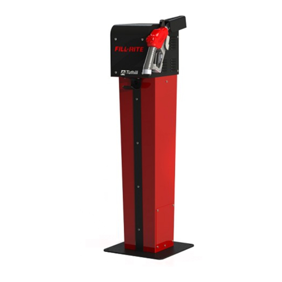
- Page 1 Owners Installation, Operation, and Safety Manual Remote Dispensing Cabinets Models FR102PH FR302DP FR902DP FR910PM mdi - Manufacturers Distributor Inc. | Phone: (813) 241 - 4900 | Fax: (813) 571 - 0422 | www.FillRitePumpSales.com | Sales@FillRitePumpSales.com...
-
Page 2: Table Of Contents
Table of Contents About This Manual ........................... 2 Safety Information ........................... 3 Locking ..............................3 Installation ............................... 3 Mechanical Installation ..........................5 Electrical Installation ..........................5 Wiring Diagrams ..........................6-13 Plumbing Instructions ..........................14 Operating Instructions ..........................14 Fluid Compatibility ..........................16 Wetted Parts ............................ -
Page 3: Safety Information
Safety Information WARNING! To ensure safe and proper operation of your equipment, it is critical to read and adhere to all of the following safety warnings and precautions. Improper installation or use of this product can cause serious bodily injury or death! 1) NEVER smoke near the dispenser, or use the dispenser near open flames when dispensing a flammable liquid! Fire can result! 2) A Fill-Rite filter should be used on the dispenser outlet to insure no foreign material is... - Page 4 Additionally, the Fill-Rite Cabinet Dispensers require a safety approved pressure relief valve be incorporated into the installation, either as part of the pump or separately at the dispenser itself. To assure proper operation your dispenser cabinet must be secured to a solid mounting surface. Fill-Rite recommends installing Cabinet Dispensers on either the KITWB Mounting Bracket kit, or the KITPD pedestal.
-
Page 5: Mechanical Installation
Mechanical Installation 1. Install the pump (if not included) securely to the top of the fuel tank per the instructions included with the pump. 2. Install mounting plate or pedestal as applicable for your installation. Refer to the mounting plate “Tank Mounting”... -
Page 6: Wiring Diagrams
FR102PH Wiring Diagram (110 VAC 60Hz) mdi - Manufacturers Distributor Inc. | Phone: (813) 241 - 4900 | Fax: (813) 571 - 0422 | www.FillRitePumpSales.com | Sales@FillRitePumpSales.com... - Page 7 FR102PH Wiring Diagram (220 VAC 60 Hz) mdi - Manufacturers Distributor Inc. | Phone: (813) 241 - 4900 | Fax: (813) 571 - 0422 | www.FillRitePumpSales.com | Sales@FillRitePumpSales.com...
- Page 8 FR302DP Wiring Diagram (110 VAC 60 Hz) Pump Wiring (110 VAC) Intrinsic Safety Barrier Wiring (110 VAC) IMPORTANT! Voltage selector switch on pump must be set to 220 VAC for 220 VAC installations (see pump manual for details). Pump comes from factory set to 110 VAC. mdi - Manufacturers Distributor Inc.
- Page 9 FR302DP Wiring Diagram (220 VAC 60 Hz) WARNING! DO NOT attempt to wire the Intrinsic Safety Barrier or the 900DP meter to 220 VAC in any way. Damage and potential destruction to those components will result. Pump Wiring (220 VAC) 220 VOLT PUMP WIRING DIAGRAM AUX LEAD RATED 1.0 AMP Figure 1...
- Page 10 FR902DP Wiring Diagram (110 VAC 60Hz) mdi - Manufacturers Distributor Inc. | Phone: (813) 241 - 4900 | Fax: (813) 571 - 0422 | www.FillRitePumpSales.com | Sales@FillRitePumpSales.com...
- Page 11 FR902DP Wiring Diagram (220 VAC 60Hz) mdi - Manufacturers Distributor Inc. | Phone: (813) 241 - 4900 | Fax: (813) 571 - 0422 | www.FillRitePumpSales.com | Sales@FillRitePumpSales.com...
- Page 12 FR910PM Wiring Diagram (110 VAC 60Hz) mdi - Manufacturers Distributor Inc. | Phone: (813) 241 - 4900 | Fax: (813) 571 - 0422 | www.FillRitePumpSales.com | Sales@FillRitePumpSales.com...
- Page 13 FR910PM Wiring Diagram (220 VAC 60Hz) mdi - Manufacturers Distributor Inc. | Phone: (813) 241 - 4900 | Fax: (813) 571 - 0422 | www.FillRitePumpSales.com | Sales@FillRitePumpSales.com...
-
Page 14: Plumbing Instructions
Plumbing Instructions IMPORTANT! Remote dispensers and tank top pumps must be installed in accordance with all local, state, and national electrical code NEC/ANSI/NFPA 70, NFPA 30, NFPA 30A, and NFPA 395. Your Fill-Rite dispenser cabinet should be installed in a manner that does not use the plumbing to support the cabinet in any way. - Page 15 Typical Pedestal Mount Plumbing Item Description Remote Dispenser Cabinet (applicable to FR102PH, FR902DP, FR910PM) 1” Inlet Pipe 1” Shut-Off Valve Safety Breakaway Valve Electrical Conduit (Threaded rigid conduit, sealed fittings, conductor seal) Exterior Cover (Right side shown; left side not shown for clarity of installation) CAUTION! Threaded pipe joints and connections should be sealed with the appropriate sealant or sealant tape to minimize the possibility of leaks.
-
Page 16: Fluid Compatibility
For accurate measurement and to prevent dispenser damage, dispenser and piping must always be filled with liquid and be free of air. Where applicable, the meter portion of your dispenser should be calibrated per instructions in the meter manual prior to its use. 1. - Page 17 Assembly and Disassembly (cont’d) Access to the internal components is gained by removing the top and side panels. 1. Remove the screws on the front and sides of the cabinet. The screws are located around the perimeter at the top. The front screws pass through the sun visor over the display on metering cabinets.
-
Page 18: Cabinet Exterior Dimensions
FR102PH Dispenser Cabinet Measurements Nozzle Boot Power Switch Nozzle Rest Hose Hook mdi - Manufacturers Distributor Inc. | Phone: (813) 241 - 4900 | Fax: (813) 571 - 0422 | www.FillRitePumpSales.com | Sales@FillRitePumpSales.com... - Page 19 FR302DP and FR902DP Cabinet Measurements Nozzle Boot Power Switch Nozzle Rest Hose Hook Nozzle Boot Power Switch Nozzle Rest Hose Hook 57.74 mdi - Manufacturers Distributor Inc. | Phone: (813) 241 - 4900 | Fax: (813) 571 - 0422 | www.FillRitePumpSales.com | Sales@FillRitePumpSales.com...
- Page 20 FR910PM Precision Meter Cabinet Dimensions Nozzle Boot Power Switch Nozzle Rest Hose Hook Nozzle Boot Power Switch Nozzle Rest Hose Hook mdi - Manufacturers Distributor Inc. | Phone: (813) 241 - 4900 | Fax: (813) 571 - 0422 | www.FillRitePumpSales.com | Sales@FillRitePumpSales.com...
Need help?
Do you have a question about the Fill-Rite FR102PH and is the answer not in the manual?
Questions and answers