
Related Manuals for Peimar EDITUS Series


Summary of Contents for Peimar EDITUS Series
- Page 1 EDITUS LINE - MAGNUS LINE Manuale dell’Utente Inverter Trifase User Manual Three Phase Inverters www.peimar.com...
- Page 3 Si precisa che i dati tecnici, le informazioni e le raffigurazioni riportate nel presente documento mantengono un valore puramente indicativo. Peimar si riserva in qualsiasi momento e senza preavviso di modificare i dati, i disegni e le informazioni riportate nel...
-
Page 4: Table Of Contents
Indice Capitolo 1 Misure di sicurezza ................6 1.1 Campo d’applicazione ............6 1.2 Istruzioni di sicurezza ............. 6 1.3 Personale interessato ............. 6 Capitolo 2 Preparazione ..................7 2.1 Istruzioni di sicurezza ............. 7 2.2 Spiegazione dei simboli ............8 Capitolo 3 Informazioni sul prodotto .............. - Page 5 Capitolo 6 Istruzioni per il debugging..............33 6.1 Presentazione dell’interfaccia uomo-macchina ....33 6.2 Configurazione al primo avvio ..........34 6.3 Display dell’inverter .............. 36 6.4 Impostare i parametri generali dell’inverter ......37 6.5 Registro dei parametri dell'inverter ........48 Capitolo 7 Codici di errore e risoluzione dei problemi ........
-
Page 6: Misure Di Sicurezza
Capitolo 1 - Misure di sicurezza 1.1 Campo d’applicazione Questo manuale d’uso definisce istruzioni e procedure dettagliate per l’installazione, il funzionamento, la manutenzione e la risoluzione dei problemi dei seguenti inverter Peimar connessi alla rete elettrica: PSI-J12000-TP PSI-J15000-TP PSI-J17000-TP PSI-J20000-TP... -
Page 7: Preparazione
Qualsiasi azione non autorizzata, tra cui la modifica di qualsiasi tipo di funzionalità del prodotto, può comportare un pericolo letale per l’operatore, per terzi, per i componenti o le loro caratteristiche. In tali casi Peimar non è responsabile per perdita e per reclami in garanzia. •... -
Page 8: Spiegazione Dei Simboli
ATTENZIONE • L’inverter fotovoltaico può raggiungere elevate temperature durante il funzionamento. Si prega di non toccare il dissipatore di calore o la superficie laterale durante il funzionamento o subito dopo lo spegnimento. • Rischio di danni dovuti a modifiche improprie. AVVISO •... - Page 9 PERICOLO parti calde Gli elementi all’interno dell’inverter raggiungono elevate temperature durante il funzionamento. Non toccare la custodia metallica quando l’inverter è attivo (rischio di ustione). SI È VERIFICATO UN ERRORE Si rimanda al Capitolo 7 “Codici di Errore e Risoluzione dei Problemi”...
-
Page 10: Informazioni Sul Prodotto
Capitolo 3 - Informazioni sul prodotto 3.1 Campo di impiego I prodotti delle serie Editus e Magnus sono inverter trifase senza trasformatore, da connettere alla rete elettrica. Essi sono componenti fondamentali negli impianti fotovoltaici connessi in rete. Gli inverter Editus e Magnus ricevono l’energia elettrica generata in corrente continua (CC) dai pannelli solari e la convertono in corrente alternata (CA) conformemente ai requisiti della rete pubblica, per poter essere dunque utilizzata per l’alimentazione delle utenze elettriche dell’abitazione o della propria attività,... -
Page 11: Panoramica E Dimensioni Dei Prodotti
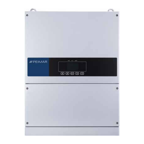
3.2 Panoramica e dimensioni dei prodotti 450 mm Serie Editus PSI-J12000-TP / PSI-J15000-TP / PSI-J17000-TP / PSI-J20000-TP 530 mm Serie Magnus PSI-J25000-TP / PSI-J33000-TP 550 mm Serie Magnus PSI-J40000-TP / PSI-J50000-TP / PSI-J60000-TP... -
Page 12: Scheda Tecnica - Editus Line
3.3 Scheda tecnica - EDITUS LINE PSI-J12000-TP PSI-J15000-TP PSI-J17000-TP PSI-J20000-TP Ingresso CC Potenza massima CC 14520 W 18150 W 20570 W 24200 W Tensione massima CC 1000 V 1000 V 1000 V 1000 V 180-900 V 180-900 V 180-900 V Range di tensione MPPT 180-900 V Tensione nominale CC... - Page 13 Staffa di fissaggio a parete Montaggio 640 x 450 x 232 mm Dimensioni (H x L x P) Peso netto 29 kg 33 kg 5 Anni (standard) / 10 Anni (opzionale) Garanzia Certificati Per un elenco completo dei certificati fare riferimento al sito www.peimar.com...
-
Page 14: Scheda Tecnica - Magnus Line
3.4 Scheda tecnica - MAGNUS LINE PSI-J25000-TP PSI-J33000-TP Ingresso CC Potenza massima CC 30300 W 36300 W Tensione massima CC 1000 V 1000 V 180-900 V Range di tensione MPPT 180-900 V Tensione nominale CC 600 V 600 V Tensione di avvio 200 V 200 V Tensione minima CC... - Page 15 Staffa di fissaggio a parete Montaggio 700 x 530 x 260 mm Dimensioni (H x L x P) 48 kg Peso netto 5 Anni (standard) / 10 Anni (opzionale) Garanzia Certificati Per un elenco completo dei certificati fare riferimento al sito www.peimar.com...
-
Page 16: Scheda Tecnica - Magnus Line
3.5 Scheda tecnica - MAGNUS LINE PSI-J40000-TP PSI-J50000-TP PSI-J60000-TP Ingresso CC Potenza massima CC 48400 W 60500 W 72000 W Tensione massima CC 1000 V 1000 V 1000 V 280-900 V 280-900 V Range di tensione MPPT 280-900 V Tensione nominale CC 600 V 600 V 600 V... - Page 17 Staffa di fissaggio a parete Montaggio 800 x 550 x 280 mm Dimensioni (H x L x P) 68 kg Peso netto 5 Anni (standard) / 10 Anni (opzionale) Garanzia Certificati Per un elenco completo dei certificati fare riferimento al sito www.peimar.com...
-
Page 18: Istruzioni Per L'installazione
Il luogo di installazione deve essere ben ventilato. 4.2 Controllo prima dell’installazione 4.2.1 Controllare l’imballaggio Sebbene gli inverter Peimar abbiano superato collaudi rigorosi e vengano controllati prima che lascino la fabbrica, non è escluso che possano subire dei danni durante il trasporto. -
Page 19: Individuazione Modalità E Posizione Di Installazione
4.3 Individuazione modalità e posizione di installazione 4.3.1 Modalità di montaggio Si prega di montare l’inverter correttamente. MAX 15° Il dispositivo viene raffreddato mediante convezione naturale e ventilazione regolata. Può essere installato in ambienti interni o esterni. 2. Si prega di installare il dispositivo come in figura. Si consiglia l’installazione verticale, o con un’inclinazione massima di 15°... - Page 20 Per assicurare un’adeguata ventilazione nel luogo di installazione, in caso di compresenza nella medesima area di diversi inverter fotovoltaici Peimar, è necessario rispettare le distanze minime di sicurezza indicate. 30 cm 50 cm 50 cm 80 cm 80 cm 80 cm...
-
Page 21: Procedura Di Montaggio
4.4 Procedura di montaggio 4.4.1 Segnare i punti di perforazione per il montaggio della staffa di ancoraggio La posizione di montaggio deve essere segnata come mostrato. Serie Editus PSI-J12000-TP / PSI-J15000-TP / PSI-J17000-TP / PSI-J20000-TP Serie Magnus PSI-J25000-TP / PSI-J33000-TP... - Page 22 Serie Magnus PSI-J40000-TP / PSI-J50000-TP / PSI-J60000-TP 4.4.2 Perforare e posizionare i tasselli di fissaggio Praticare nel muro 8 fori in corrispondenza dei punti segnati in base alla posizione della staffa e successivamente inserirvi i tasselli di fissaggio utilizzando un martello di gomma.
- Page 23 Serie Magnus PSI-J25000-TP / PSI-J33000-TP Serie Magnus PSI-J40000-TP / PSI-J50000-TP / PSI-J60000-TP...
- Page 24 4.4.3 Applicare le viti e montare la staffa di ancoraggio Le staffe devono essere installate in posizione tramite viti 4.4.4 Montare l’inverter Appendere con attenzione l’inverter. Assicurarsi che la parte posteriore del dispositivo sia a stretto contatto con la staffa. Utilizzare le apposite viti per bloccare l’inverter alla staffa.
-
Page 25: Connessione Elettrica
Capitolo 5 - Connessione elettrica 5.1 Istruzioni di sicurezza per lavori sulla linea di alimentazione La connessione elettrica deve essere effettuata esclusivamente da tecnici professionisti. Si tenga presente che l’inverter è un dispositivo a doppia alimentazione elettrica. Prima della connessione i tecnici devono munirsi dei necessari dispositivi di protezione, tra cui guanti isolanti, scarpe isolanti e casco protettivo. -
Page 26: Caratteristiche Degli Ingressi Di Connessione
5.2 Caratteristiche degli ingressi di connessione DC SWITCH Ingresso CC RS-485 RS-232 Porta connessione messa a terra Valvola di decompressione Sezionatore CC Ingresso di connessione CA 5.3 Connessione lato CA Raccomandato cavo di rame Tipologia Sezione cavi mm Sezione cavi (mm Sezione cavi mm Diametro esterno (mm) PSI-J12000-TP... - Page 27 5.3.1 Aprire la scocca frontale inferiore dell'inverter Allacciare il cavo CA attraverso il foro corrispondente, connettendo le 3 fasi, il neutro e la linea di terra ai terminali all'interno dell'inverter.
-
Page 28: Connessione Lato Cc
5.3.2 Assicurare ogni parte del connettore per renderlo impermeabile e ripristinare la scocca con le viti 5.4 Connessione lato CC Sezione dei cavi (mm²) Diametro esterno dei cavi (mm) Minimo-massimo Valore consigliato 4.0-6.0 4.2-5.3 La connessione CC è costituita dal connettore positivo e dal connettore negativo. Vite di bloccaggio Involucro isolante... - Page 29 Vite di bloccaggio Involucro isolante AVVISO • Posizionare separatamente connettore dopo disimballaggio per evitare errori nella connessione dei cavi. • Collegare il connettore positivo al polo positivo dei pannelli solari, e il connettore negativo al polo negativo dei pannelli solari. Assicurarsi che la connessione sia effettuata nella corretta posizione.
- Page 30 3. Inserire il cavo positivo e quello negativo nelle rispettive viti di bloccaggio. 4. Inserire i terminali metallici positivo e negativo nei rispettivi cavi a cui è stato rimosso la guaina isolante, e bloccarli saldamente mediante una pinza crimpatrice. Assicurarsi che la forza di estrazione del cavo pressato sia superiore a 400N.
-
Page 31: Connessione Dell'interfaccia Di Comunicazione
L'interfaccia RS-232 può essere connessa al modulo ethernet utilizzabile per il monitoraggio dello stato di funzionamento. Per ulteriori dettagli, fare riferimento alla relativa guida (allegata al dispositivo o scaricabile dal sito www.peimar.com). In alternativa, connettendosi alla rete internet tramite il modulo Wi-Fi (opzionale) e caricando i dati dell'inverter sul server, gli utenti possono monitorare le informazioni di funzionamento da remoto. - Page 32 Presa elettrica Terminale Manicotto di plastica Cavo B (-) Cavo A (+) Cavo schermato in metallo...
-
Page 33: Istruzioni Per Il Debugging
Capitolo 6 - Istruzioni per il debugging 6.1 Presentazione dell’interfaccia uomo-macchina • Spia blu lampeggiante: ricezione dati COMM • Spia gialla lampeggiante: invio dei dati • Spia rossa: errore FAULT • Spia verde: in funzione Quando le spie sono spente, l'inverter è in stato di inizializzazione POWER La spia gialla indica il normale funzionamento dell'inverter Tasto ◄... -
Page 34: Configurazione Al Primo Avvio
I tasti presenti sull’inverter consentono di navigare nel menu per ottenere informazioni sul funzionamento e sui parametri operativi. Questi cinque pulsanti possono essere usati ripetitivamente. 6.2 Configurazione al primo avvio 6.2.1 Impostare la lingua Per accendere l'inverter ruotare il sezionatore CC su ON. Quando l’inverter fotovoltaico inizia a funzionare per la prima volta, deve essere selezionata la lingua, la data e l'ora. - Page 35 Se lo Standard di utilizzo non è presente tra le opzioni disponibili, interrompere la configurazione e rivolgersi all’assistenza tecnica Peimar. NB: Si raccomanda, prima di connettere l'inverter alla rete, di impostare la modalità di ingresso delle stringhe fotovoltaiche accedendo alla funzione "Impos.
-
Page 36: Display Dell'inverter
6.3 Display dell’inverter Menu principale Stat. Opzioni Registro Info Impos. E-Oggi Parametri CA comunicazione E-Mese Lingua & Ora Parametri CC E-Anno Standard rete Regist. errori E-Tot. Azzera errori Info Wi-Fi Esci Azzera energia Esci Opzioni LCD Reset fabbrica Modifica password Impos. -
Page 37: Impostare I Parametri Generali Dell'inverter
6.4 Impostare i parametri generali dell’inverter Statistiche Nell'interfaccia principale premere il pulsante “ENT” per accedere al menu. Premere i tasti ▼ o ▲ per selezionare. Il display LCD mostrerà la capacità di produzione giornaliera, mensile, annuale e totale. Stat. Opzioni Registro Info E-Oggi... - Page 38 2. Premere “ENT” per accedere a “Impos. comunicazione” . Premere ▼ e ▲ per impostare l'indirizzo di comunicazione di RS-232 e RS-485. Stat. Opzioni Registro Info Potenza RS232 indiriz: E-Oggi RS232 baudrate: 115200 bit/s 0.00 kWh RS485 indiriz: E-Tot. 0.00 kWh RS485 baudrate: 9600 bit/s...
- Page 39 2. Premere ▼ e quindi “ENT” per accedere a "Lingua & Ora". Premere ▼ e ▲ per impostare la lingua, la data e l'ora. Stat. Opzioni Registro Info Potenza Lingua: Italiano E-Oggi Data: 05/11/2018 0.00 kWh E-Tot. 15:47:56 0.00 kWh T-Oggi 0.0 h Torna...
- Page 40 Premere ▼ e quindi “ENT” per inserire la password e accedere alle impostazioni del Paese. Attenzione password predefinita: "123456". Stat. Opzioni Registro Info Potenza Verifica Inserire password! E-Oggi 0.00 kWh E-Tot. 0.00 kWh T-Oggi 0.0 h Canc. T-Tot. 0.0 h Normal E-Oggi 0.00 kWh 05-11-19...
- Page 41 Azzera errori Nell'interfaccia principale premere il pulsante “ENT” per accedere al menu, poi il tasto ► per accedere alle "Opzioni". Attenzione password predefinita: "123456". Stat. Opzioni Registro Info Impos. comunicazione Potenza Lingua & Ora 10.8 Standard rete Azzera errori E-Oggi Azzera energia 0.00 kWh Opzioni LCD...
- Page 42 Azzera energia Nell'interfaccia principale premere il pulsante “ENT” per accedere al menu, poi il tasto ► per accedere alle "Opzioni". Stat. Opzioni Registro Info Impos. comunicazione Potenza Lingua & Ora 10.8 Standard rete Azzera errori E-Oggi Azzera energia 0.00 kWh Opzioni LCD Reset fabbrica E-Tot.
- Page 43 Opzioni LCD Nell'interfaccia principale premere il pulsante “ENT” per accedere al menu, poi il tasto ► per accedere alle "Opzioni". Stat. Opzioni Registro Info Impos. comunicazione Potenza Lingua & Ora 10.8 Standard rete Azzera errori E-Oggi Azzera energia 0.00 kWh Opzioni LCD Reset fabbrica E-Tot.
- Page 44 Reset fabbrica Nell'interfaccia principale premere il pulsante “ENT” per accedere al menu, poi il tasto ► per accedere alle "Opzioni". Stat. Opzioni Registro Info Impos. comunicazione Potenza Lingua & Ora 10.8 Standard rete Azzera errori E-Oggi Azzera energia 0.00 kWh Opzioni LCD Reset fabbrica E-Tot.
- Page 45 3. Fare click su Ok per salvare le modifiche. L'inverter si riavvia automaticamente. Stat. Opzioni Registro Info Potenza E-Oggi 0.00 kWh Attenzione: premendo "OK" tutte E-Tot. statistiche e il registro errori verranno 0.00 kWh cancellati! T-Today 1.7 h Canc. T-Tot. 0.0 h Normal Reset fabbrica...
- Page 46 2. Premere ▼ e quindi “ENT” per inserire la password e accedere a "Reset password". Attenzione password predefinita: "123456". Stat. Opzioni Registro Info Potenza Verifica Inserire password! E-Oggi 0.00 kWh E-Tot. 0.00 kWh T-Oggi 0.0 h Canc. T-Tot. 0.0 h Normal E-Oggi 0.00 kWh 05-11-19...
- Page 47 Impostazione modalità fotovoltaica Nell'interfaccia principale premere il pulsante “ENT” per accedere al menu, poi il tasto ► per accedere alle "Opzioni". Stat. Opzioni Registro Info Impos. comunicazione Potenza Lingua & Ora 10.8 Standard rete Azzera errori E-Oggi Azzera energia 0.00 kWh Opzioni LCD Reset fabbrica E-Tot.
-
Page 48: Registro Dei Parametri Dell'inverter
6.5 Registro dei parametri dell'inverter Registro dei parametri operativi Nell'interfaccia principale premere il pulsante “ENT” per accedere al menu, poi il tasto ► per accedere ai parametri. 2. Premere il pulsante “ENT” per accedere a "Registro". Premere ▼ e ▲ per selezionare i parametri. -
Page 49: Codici Di Errore E Risoluzione Dei Problemi
Capitolo 7 - Codici di errore e risoluzione dei problemi 7.1 Codice errore e descrizione Errore 01 Errore relè (Master) Errore 02 Errore memoria EEPROM (Master) Errore 03 Temperatura elevata (Master) Errore 04 Temperatura bassa (Master) Errore 05 Comunicazione interna persa (Master) Errore 06 Errore dispositivi GFCI (Master) Errore 07... - Page 50 Errore 45 - 46 - 47 - 48 Errore ventole 1 - 2 - 3 - 4 (Master) Errore 49 Comunicazione persa DSP power meter Errore 50 Comunicazione interna persa (Slave) Errore 51 - 52 - 53 L1 - L2 -L3 Errore di coerenza dei dati di tensione (Slave) Errore 54 - 55 - 56 L1 - L2 - L3 Errore di coerenza dei dati di frequenza (Slave) Errore 57...
-
Page 51: Indicazione Errore E Risoluzione Del Problema
Controllare l’impostazione del Paese e la frequenza della rete Errore di frequenza elettrica locale; se le suddette condizioni sono nella norma, siete pregati di contattare il vostro rivenditore o l’assistenza tecnica Peimar. Controllare lo stato di connessione tra il lato CA dell’inverter e la Errore di assenza di rete elettrica;... - Page 52 Controllare le impostazioni dei pannelli solari. I tecnici Peimar Tensione Bus elevata possono aiutarvi. Se le suddette condizioni sono nella norma, siete pregati di contattare il vostro rivenditore o l’assistenza tecnica Peimar. Se questo errore è sempre presente, siete pregati di contattare il Corrente PV elevata vostro rivenditore o l’assistenza tecnica Peimar.
-
Page 53: Riciclaggio E Smaltimento
è necessario restituirlo al proprio rivenditore o smaltirlo presso un centro autorizzato di raccolta e riciclaggio nella propria zona. Capitolo 9 - Servizio di Garanzia Per le condizioni di garanzia fare riferimento al relativo documento scaricabile dal sito internet www.peimar.com... - Page 54 Note:...
- Page 55 Note:...
- Page 57 It is important to point out, that all technical specifications, information and figures contained in this document are estimated values. Peimar reserves the right to change the technical specifications, information and figures contained in this document at any time and...
- Page 58 Content Chapter 1 Safety precautions ................60 1.1 Scope of application ............. 60 1.2 Safety instructions ..............60 1.3 Target group ................60 Chapter 2 Preparation ..................61 2.1 Safety instructions ..............61 2.2 Explanations of symbols ............62 Chapter 3 Product information ................
- Page 59 Chapter 6 Debugging instructions ..............87 6.1 Introduction of human-computer interface ......87 6.2 First run setup ..............88 6.3 Display of the inverter ............90 6.4 Settings of general parameters of the inverter ..... 91 6.5 Inquiry of parameters of inverter ........102 Chapter 7 Fault code and troubleshooting .............
-
Page 60: Safety Precautions
Chapter 1 - Safety precautions 1.1 Scope of application This user manual describes instructions and detailed procedures for installing, operating, maintaining, and troubleshooting of the following Peimar grid-tied inverters: PSI-J12000-TP PSI-J15000-TP PSI-J17000-TP PSI-J20000-TP PSI-J25000-TP PSI-J33000-TP PSI-J40000-TP PSI-J50000-TP PSI-J60000-TP Please keep this manual all time available in case of emergency. -
Page 61: Preparation
Peimar is not responsible for the loss and these warranty claims. • The Peimar inverter must only be operated with PV generator. Do not connect any other source of energy to the Peimar inverter. • Be sure that the PV generator and inverter are well grounded... -
Page 62: Explanations Of Symbols
CAUTION • The PV inverter will become hot during operation. Please do not touch the heat sink or peripheral surface during or shortly after operation. • Risk of damage due to improper modifications. NOTICE • The PV inverter is designed to feed AC power directly to the public utility power grid;... - Page 63 AN ERROR HAS OCCURRED Please go to Chapter 7 “Troubleshooting” to remedy the error. This device SHALL NOT be disposed of as residential waste. Please go to Chapter 8 “Recycling and Disposal” for proper treatments. ROHS Restriction of Hazardous Substances Directive WITHOUT TRANSFORMER This inverter does not use transformer for the isolation function.
-
Page 64: Product Information
Chapter 3 - Product information 3.1 Application scope of products Editus and Magnus series products are grid-tied three phase inverters without transformers, and the inverters are important components of grid-tied solar power systems. The Editus and Magnus inverters change the DC generated by solar panels into AC which is in accordance with the requirements of public grid and send the AC into the grid. -
Page 65: Overview And Dimensions Of Products
3.2 Overview and dimensions of products 450 mm Editus series PSI-J12000-TP / PSI-J15000-TP / PSI-J17000-TP / PSI-J20000-TP 530 mm Magnus series PSI-J25000-TP / PSI-J33000-TP 550 mm Magnus series PSI-J40000-TP / PSI-J50000-TP / PSI-J60000-TP... -
Page 66: Datasheet - Editus Line
3.3 Datasheet - EDITUS LINE PSI-J12000-TP PSI-J15000-TP PSI-J17000-TP PSI-J20000-TP Input DC Max. DC Power 14520 W 18150 W 20570 W 24200 W Max. DC Voltage 1000 V 1000 V 1000 V 1000 V 180-900 V 180-900 V 180-900 V MPPT Voltage range 180-900 V Nominal DC Voltage 600 V... - Page 67 Ingress Protection Rear Panel Mounting 640 x 450 x 232 mm Dimensions (H x W x D) [mm] Net Weight 29 kg 33 kg 5 (standard) / 10 (optional) Standard [Year] Certificates For a complete list of certificates visit www.peimar.com...
-
Page 68: Datasheet - Magnus Line
3.4 Datasheet - MAGNUS LINE PSI-J25000-TP PSI-J33000-TP Input DC Max. DC Power 30300 W 36300 W Max. DC Voltage 1000 V 1000 V 180-900 V MPPT Voltage range 180-900 V Nominal DC Voltage 600 V 600 V Start Voltage 200 V 200 V Min. - Page 69 IP65 (Indoor & Outdoor Installation) Ingress Protection Rear Panel Mounting 700 x 530 x 260 mm Dimensions (H x W x D) [mm] 48 kg Net Weight 5 (standard) / 10 (optional) Standard [Year] Certificates For a complete list of certificates visit www.peimar.com...
-
Page 70: Datasheet - Magnus Line
3.5 Datasheet - MAGNUS LINE PSI-J40000-TP PSI-J50000-TP PSI-J60000-TP Input DC Max. DC Power 48400 W 60500 W 72000 W Max. DC Voltage 1000 V 1000 V 1000 V 280-900 V 280-900 V MPPT Voltage range 280-900 V Nominal DC Voltage 600 V 600 V 600 V... - Page 71 Ingress Protection Rear Panel Mounting 800 x 550 x 280 mm Dimensions (H x W x D) [mm] 68 kg Net Weight 5 Anni (standard) / 10 Anni (opzionale) Standard [Year] Certificates For a complete list of certificates visit www.peimar.com...
-
Page 72: Instructions For Installation
The installation site must be well ventilated. 4.2 Pre-installation check 4.2.1 Check the package Although Peimar’s inverters have surpassed stringent testing and are checked before they leave the factory, it is possible that the inverters may suffer damages during transportation. -
Page 73: The Determination Of The Installation Method And Position
4.3 The determination of the installation method and position 4.3.1 Mounting method Please mount the inverter correctly. MAX 15° The equipment employs natural convection cooling and regulated ventilation, it can be installed indoor or outdoor. 2. Please install the device as shown in the figure. Vertical installation on floor level is recommended. - Page 74 To make sure the installation spot is suitably ventilated, if multiple Peimar grid-tied solar inverters are installed same area, the following safety clearance in figure. Shall be followed for proper ventilation conditions. 30 cm 50 cm 50 cm 80 cm...
-
Page 75: Mounting Procedure
4.4 Mounting procedure 4.4.1 Mark the positions of the drill holes of the rear panel The mounting position should be marked as shown. Editus series PSI-J12000-TP / PSI-J15000-TP / PSI-J17000-TP / PSI-J20000-TP Magnus series PSI-J25000-TP / PSI-J33000-TP... - Page 76 4.4.2 Drill holes and place the expansion tubes According to the guides, drill 8 holes in the wall in conformity with position marked and then place expansion tubes in the holes using a rubber mallet. Editus series PSI-J12000-TP / PSI-J15000-TP / PSI-J17000-TP / PSI-J20000-TP...
- Page 77 Magnus series PSI-J25000-TP / PSI-J33000-TP Magnus series PSI-J40000-TP / PSI-J50000-TP / PSI-J60000-TP...
- Page 78 4.4.3 Mount the screws and the rear panel The panels should be mounted in the mounting position by screws as shown. 4.4.4 Mount the inverter Carefully mount the inverter to the rear panel as shown. Make sure that the rear part of the equipment is closely mounted to the rear panel.
-
Page 79: Electrical Connection
Chapter 5 - Electrical connection 5.1 Safety instruction for hot-line job Electrical connection must only be operated on by professional technicians. Please keep in mind that the inverter is a bi-power supply equipment. Before connection, necessary protective equipment must be employed by technicians including insulating gloves, insulating shoes and safety helmet. -
Page 80: Specifications For Electrical Interface
5.2 Specifications for electrical interface DC SWITCH DC Input RS-485 RS-232 Ground Connecting port Decompression valves DC Switch AC output 5.3 AC side connection Recommended copper cable Type Sezione cavi mm Cross section area (mm Sezione cavi mm External diameter (mm) PSI-J12000-TP Sezione cavi mm 4x6+1x4... - Page 81 5.3.1 Open the lower front cover of the inverter Feed AC cable through the AC cable hole, and connect the cable to terminals as the marks L1,L2,L3,N,PE shows...
-
Page 82: Dc Side Connection
5.3.2 Secure each part of the connector to make it waterproof and cover the lid with screws 5.4 DC side connection Cross-sectional Area of Cables (mm²) Outside Diameter of the Cables (mm) Scope Recommended Value 4.0-6.0 4.2-5.3 DC connector is made up of the positive connector and the cathode connector. Lock Screw Insulated Enclosure... - Page 83 Lock Screw Insulated Enclosure NOTICE • Please place the connector separately after unpacking in order to avoid confusion for connection of cables. • Please connect the positive connector to the positive side of the solar panels, and connect the cathode connector to the cathode side of the solar side.
- Page 84 3. Feed the positive and cathode cables into corresponding lock screws. 4. Put the metal positive and cathode terminals into positive cable and cathode cable whose insulated enclosure has been stripped, and crimp them tightly with a wire crimper. Make sure that the withdrawal force of the pressed cable is bigger than 400N.
-
Page 85: Connection To Communication And Monitoring Interface
The RS-232 interface can be connected to the Ethernet module which can be used for monitoring the operating status. For further details, refer to the relevant guide (attached to the device or downloadable from the website www.peimar.com). Alternatively, by connecting to the internet via the Wi-Fi module (optional) and uploading the inverter data to the server, users can monitor operation information remotely. - Page 86 Socket Terminal Plastic Sleeve Cable B (-) Cabla A (+) Metal-shielded wire...
-
Page 87: Debugging Instructions
Chapter 6 - Debugging instructions 6.1 Introduction of human-computer interface • Flashing blue light: receiving data COMM • Flashing yellow light: sending data • Red light: error FAULT • Green light: working When light are off the inverter is in initializing state POWER The yellow light is on during normal operation of the device Button ◄... -
Page 88: First Run Setup
The buttons on the inverter allow you to navigate the menu for inquiry information on operation and operating parameters. These five buttons can be used repeatedly. 6.2 First run setup 6.2.1 Set the language In order to power on the inverter, turn on DC switch. When the solar inverter begins to run for the first time, please configure the language, and the inverter LCD will display as below: Graph... - Page 89 An incorrect choice leads to malfunction of the device. If users can not locate the corresponding country, please abort the setting and contact Peimar assistance. Note: we recommend, before connecting inverter to the grid, to select PV strings input mode, entering "PV mode setting"...
-
Page 90: Display Of The Inverter
6.3 Display of the inverter Main Menu Graph Setting Run-Info About E-Today Communicate Set AC-Parameters E-Month Language &Time DC-Parameters E-Year Grid Compliance Error Records E-Total Clear Errors Module-Inform Exit Clear Energy Exit LCD Setting Factory Reset Change Password PV Mode Setting Authorization Export limit... -
Page 91: Settings Of General Parameters Of The Inverter
6.4 Settings of general parameters of the inverter Graph Set In the main LCD interface, press “ENT” button to enter into the menu, press ▼ or ▲ to select. The LCD displays daily, monthly, yearly and gross generating capacity. Graph Setting Run-Info About... - Page 92 Press “ENT” to enter into “Communication Set” . Press ▼ and ▲ to set the communication address of RS-232 and RS-485. The Fault address is 1. Graph Setting Run-Info About Power RS232 address: E-Today RS232 baudrate: 115200 bit/s 0.00 kWh RS485 address: E-Total 0.00 kWh...
- Page 93 2. Press ▼ and then press “ENT” to enter into “Language & Time” . Press ▲ and ▼ to set the language, date and time. Graph Setting Run-Info About Power Language: English E-Today Date: 30/10/2018 0.00 kWh E-Total Time: 13:23:56 0.00 kWh T-Today 0.0 h...
- Page 94 2. Press ▼ and then press "ENT” to enter password and enter into country setting. Attention default password: "123456". Graph Setting Run-Info About Power Verify Please enter password! E-Today 0.00 kWh E-Total 0.00 kWh T-Today 0.0 h Cancel T-Total 0.0 h Normal E-Today 0.00 kWh 05-11-19...
- Page 95 Clear Errors In the main LCD interface, press “ENT” button, then press ► to enter into “Setting” . "Attention default password: "123456". Graph Setting Run-Info About Communicate set Power Language & Time 10.8 Grid Compliance Clear Errors E-Today Clear Energy 0.00 kWh LCD Setting Factory Reset...
- Page 96 Clear Energy In the main LCD interface, press “ENT” button, then press ► to enter into “Setting” . Attention default password: "123456". Graph Setting Run-Info About Communicate set Power Language & Time 10.8 Grid Compliance Clear Errors E-Today Clear Energy 0.00 kWh LCD Setting Factory Reset...
- Page 97 LCD Setting In the main LCD interface, press “ENT” button, then press ► to enter into “Setting” . Graph Setting Run-Info About Communicate set Power Language & Time 10.8 Grid Compliance Clear Errors E-Today Clear Energy 0.00 kWh LCD Setting Factory Reset E-Total Change Password...
- Page 98 Factory Reset In the main LCD interface, press “ENT” button, then press ► to enter into “Setting” . Graph Setting Run-Info About Communicate set Power Language & Time 10.8 Grid Compliance Clear Errors E-Today Clear Energy 0.00kWh LCD Setting Factory Reset E-Total Change Password 0.00 kWh...
- Page 99 3. Click OK to save the changes. Inverter restart automatically. Graph Setting Run-Info About Power Attention: if you click the button “OK” , all E-Today generated energy datas and error records 0.00kWh saved in inverter will be deleted permanently! the password and grid compliance etc. will E-Total be reset to factory setting.
- Page 100 2. Press ▼ and then press ENT to enter password, and then enter into Reset Password. "Attention default password: 123456" Graph Setting Run-Info About Power Verify Please enter password! E-Today 0.00 kWh E-Total 0.00 kWh T-Today 0.0 h Cancel T-Total 0.0 h Normal E-Today 0.00 kWh...
- Page 101 PV Mode Setting In the main LCD interface, press “ENT” button, then press ► to enter into "Setting". Graph Setting Run-Info About Communicate set Power Language & Time 10.8 Grid Compliance Clear Errors E-Today Clear Energy 0.00 kWh LCD Setting Factory Reset E-Total Change Password...
-
Page 102: Inquiry Of Parameters Of Inverter
6.5 Inquiry of parameters of Inverter Inquiry of operating parameters In the main LCD interface, press “ENT” button, then press ► to enter into “Parameters” . 2. Press ENT to enter into “Run-Info” , then press ▼or ▲to select the needed parameters,press ENT to enter and to check the parameters. -
Page 103: Fault Code And Troubleshooting
Chapter 7 - Fault code and troubleshooting 7.1 Fault code and explanation Error Code 1 Relay Error (Master) Error Code 2 Storer Error (Master) Error Code 3 High Temperature (Master) Error Code 4 Low Temperature Master) Error Code 5 Lost Interior Communication Master) Error Code 6 GFCI Devices Error (Master) Error Code 7... - Page 104 Error Code 45 - 46 - 47 - 48 Fan 1 - 2 - 3 - 4 Error Master Error Code 49 Lost Communication between DSP and PowerMeter Error Code 50 Lost interior communication (Slave) Error Code 51 - 52 - 53 L1 - L2 - L3 Data Consistency of Voltage Error (Slave) Error Code 54 - 55 - 56 L1 - L2 - L3 Data Consistency of Frequency Error (Slave)
-
Page 105: Fault Information And Troubleshooting
Check whether the radiator is blocked, whether the inverter is in too Temperature High Error high or too low temperature, if the above mentioned are in normal, please contact your DNO or contact Peimar assistance. If this error occurs frequently, please contact your DNO or contact GFCI Device Error Peimar assistance. - Page 106 Current High mentioned are normal, please contact your DNO or contact Peimar assistance. Check the settings of the solar panel. Peimar designer can help Bus Voltage High you. If the above mentioned are normal, please contact your DNO or contact Peimar assistance.
-
Page 107: Recycling And Disposal
Chapter 9 - Guarantee Service For warranty conditions please refer to the document downloadable from the website www.peimar.com... - Page 108 Note:...
- Page 109 Note:...
- Page 112 | www.peimar.com Version: 2020_05_00...
Need help?
Do you have a question about the EDITUS Series and is the answer not in the manual?
Questions and answers