Chapters
Table of Contents
Troubleshooting

Related Manuals for Peimar Mirus Series


Summary of Contents for Peimar Mirus Series
- Page 1 MIRUS LINE - UNICUS LINE - GEMINUS LINE Manuale dell’Utente Inverter Monofase..3 User Manual Single Phase Inverters..55 Manual de Usuario Inversor Monofásico...107 www.peimar.com...
- Page 3 Si precisa che i dati tecnici, le informazioni e le raffigurazioni riportate nel presente documento mantengono un valore puramente indicativo. Peimar si riserva in qualsiasi momento e senza preavviso di modificare i dati, i disegni e le informazioni riportate nel...
-
Page 4: Table Of Contents
Indice Capitolo 1 Misure di sicurezza ................6 1.1 Campo d’applicazione ............6 1.2 Istruzioni di sicurezza ............. 6 1.3 Persone interessate ..............6 Capitolo 2 Preparazione ..................7 2.1 Istruzioni di sicurezza ............. 7 2.2 Spiegazione dei simboli ............8 Capitolo 3 Informazioni sul prodotto .............. - Page 5 5.4 Connessione dal lato CC ............. 28 5.5 Connessione di trasmissione ..........31 Capitolo 6 Istruzioni per il debugging..............32 6.1 Presentazione dell’interfaccia uomo-macchina ....32 6.2 Configurazione al primo avvio ..........33 6.3 Display dell’inverter .............. 36 6.4 Impostare i parametri generali dell’inverter ......38 6.5 Auto test completo dell’inverter ..........
-
Page 6: Misure Di Sicurezza
Capitolo 1 - Misure di sicurezza 1.1 Campo d’applicazione Questo manuale d’uso definisce istruzioni e procedure dettagliate per l’installazione, il funzionamento, la manutenzione e la risoluzione dei problemi dei seguenti inverter Peimar connessi alla rete elettrica: PSI-J1000-TL PSI-J1500-TL PSI-J2000-TL PSI-J2500-TL PSI-J3000-TL PSI-J3000-TLM PSI-J4000-TLM... -
Page 7: Preparazione
Qualsiasi azione non autorizzata, tra cui la modifica di qualsiasi tipo di funzionalità del prodotto, può comportare un pericolo letale per l’operatore, per terzi, per i componenti o le loro caratteristiche. In tali casi Peimar non è responsabile per perdita e per reclami in garanzia. •... -
Page 8: Spiegazione Dei Simboli
ATTENZIONE • L’inverter fotovoltaico può raggiungere elevate temperature durante il funzionamento. Si prega di non toccare il dissipatore di calore o la superficie laterale durante il funzionamento o subito dopo lo spegnimento. • Rischio di danni dovuti a modifiche improprie. AVVISO •... - Page 9 PERICOLO parti calde Gli elementi all’interno dell’inverter raggiungono elevate temperature durante il funzionamento. Non toccare la custodia metallica quando l’inverter è attivo (rischio di ustione). SI È VERIFICATO UN ERRORE Si rimanda al Capitolo 7 “Codici di Errore e Risoluzione dei Problemi”...
-
Page 10: Informazioni Sul Prodotto
Capitolo 3 - Informazioni sul prodotto 3.1 Campo di impiego I prodotti delle serie Mirus, Unicus e Geminus sono inverter monofase senza trasformatore, da connettere alla rete elettrica. Essi sono componenti fondamentali negli impianti fotovoltaici connessi in rete. Gli inverter Mirus, Unicus e Geminus ricevono l’energia elettrica generata in corrente continua (CC) dai pannelli solari e la convertono in corrente alternata (CA) conformemente ai requisiti della rete pubblica, per poter essere dunque utilizzata per l’alimentazione delle utenze elettriche dell’abitazione o della... -
Page 11: Specifica Per Il Modello Di Prodotto
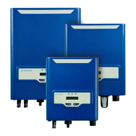
3.2 Specificazione del modello di prodotto PSI-JXXXX-TL PSI-JXXXX-TLM • PSI-J indica il nome del prodotto • XXXX indica la potenza nominale in W dell’inverter • TL indica che si tratta di un inverter senza trasformatore (transformerless) • M indica la funzionalità di doppio MPPT dell’inverter 3.3 Panoramica e dimensioni dei prodotti Le dimensioni dei prodotti sono indicate nella Figura 3.2. -
Page 12: Scheda Tecnica - Mirus Line
3.4 Scheda tecnica - MIRUS LINE PSI-J1000-TL PSI-J1500-TL Ingresso CC Potenza massima CC 1200 W 1800 W Tensione massima CC 450 V 450 V 60-425 V 60-425 V Range di tensione MPPT Tensione nominale CC 360 V 360 V Tensione di avvio 70 V 70 V Tensione minima CC... - Page 13 Staffa di fissaggio a parete Dimensioni (H x L x P) [mm] 315 x 260 x 120 5.6 kg Peso netto Garanzia [Anno] 5 (standard) / 10 (opzionale) Certificati Per un elenco completo dei certificati fare riferimento al sito www.peimar.com...
-
Page 14: Scheda Tecnica - Unicus Line
3.5 Scheda tecnica - UNICUS LINE PSI-J2000-TL PSI-J2500-TL PSI-J3000-TL Ingresso CC Potenza massima CC 2400 W 3000 W 3630 W Tensione massima CC 500 V 500 V 550 V 60-500 V Range di tensione MPPT 60-450 V 60-450 V Tensione nominale CC 360 V 360 V 360 V... - Page 15 Staffa di fissaggio a parete Dimensioni (H x L x P) [mm] 354 x 305 x 120 Peso netto 7.8 kg 8.3 kg 8.4 kg Garanzia [Anno] 5 (standard) / 10 (opzionale) Certificati Per un elenco completo dei certificati fare riferimento al sito www.peimar.com...
-
Page 16: Scheda Tecnica - Geminus Line
3.6 Scheda tecnica - GEMINUS LINE PSI-J3000-TLM PSI-J4000-TLM PSI-J5000-TLM PSI-J6000-TLM Ingresso CC Potenza massima CC 3630 W 4840 W 6050 W 7200 W Tensione massima CC 600 V 600 V 600 V 600 V 90-550 V 90-550 V Range di tensione MPPT 90-550 V 90-550 V Tensione nominale CC... - Page 17 Garanzia [Anno] Certificati Per un elenco completo dei certificati fare riferimento al sito www.peimar.com Soddisfa lo standard di rete secondo cui la massima corrente non supera i 16A per fase Soddisfa il VDE - ARN - N 4105 secondo cui la massima potenza apparente non supera i 4600 VA per fase...
-
Page 18: Istruzioni Per L'installazione
Il luogo di installazione deve essere ben ventilato. 4.2 Controllo prima dell’installazione 4.2.1 Controllare l’imballaggio Sebbene gli inverter Peimar abbiano superato collaudi rigorosi e vengano controllati prima che lascino la fabbrica, non è escluso che possano subire dei danni durante il trasporto. -
Page 19: Individuazione Metodo E Posizione Di Installazione
4.3 Individuazione modalità e posizione di installazione 4.3.1 Modalità di montaggio Si prega di montare l’inverter correttamente come mostrato nella Figura 4.1 . MAX 15° Figura 4.1 Modalità di montaggio Il dispositivo viene raffreddato mediante convezione naturale e può essere installato in ambienti interni o esterni. -
Page 20: Procedura Di Montaggio
Per assicurare un’adeguata ventilazione nel luogo di installazione, in caso di compresenza nella medesima area di diversi inverter fotovoltaici Peimar, è necessario rispettare le distanze minime di sicurezza indicate nella Figura 4.2. 30 cm 50 cm 50 cm Figura 4.2 Distanze minime 4.4 Procedura di montaggio... - Page 21 296,9 77,5 77,5 Figura 4.4 Dimensioni della staffa di PSI-J2000-TL / PSI-J2500-TL / PSI-J3000-TL Figura 4.5 Dimensioni della staffa di PSI-J3000-TLM / PSI-J4000-TLM / PSI-J5000-TLM / PSI-J6000-TLM 4.4.2 Perforare e posizionare i tasselli di fissaggio Come da istruzioni, praticare nel muro i fori in corrispondenza dei punti segnati in base alle indicazioni riportate nella Figura 4.6, Figura 4.7 e Figura 4.8.
- Page 22 77,59 Figura 4.7 Dimensioni dei fori di PSI-J2000-TL / PSI-J2500-TL / PSI-J3000-TL Figura 4.8 Dimensioni dei fori di PSI-J3000-TLM / PSI-J4000-TLM / PSI-J5000-TLM / PSI-J6000-TLM 4.4.3 Applicare le viti e montare la staffa di ancoraggio Le staffe devono essere installate nella posizione di montaggio tramite viti come mostrato nella Figura 4.9, Figura 4.10 e Figura 4.11.
- Page 23 Figura 4.10 Montaggio della staffa di PSI-J2000-TL / PSI-J2500-TL / PSI-J3000-TL Figura 4.11 Montaggio della staffa di PSI-J3000-TLM / PSI-J4000-TLM / PSI-J5000-TLM / PSI-J6000-TLM...
- Page 24 4.4.4 Montare l’inverter Fissare con attenzione l’inverter alla staffa come mostrato nella Figura 4.12, Figura 4.13 e Figura 4.14; assicurarsi che la parte posteriore del dispositivo sia montata a stretto contatto con la staffa. Utilizzare le due viti apposite per bloccare l’inverter alla staffa.
-
Page 25: Connessione Elettrica
Capitolo 5 - Connessione elettrica 5.1 Istruzioni di sicurezza per lavori sulla linea di alimentazione La connessione elettrica deve essere effettuata esclusivamente da tecnici professionisti. Si tenga presente che l’inverter è un dispositivo a doppia alimentazione elettrica. Prima della connessione i tecnici devono munirsi dei necessari dispositivi di protezione, tra cui guanti isolanti, scarpe isolanti e casco protettivo. -
Page 26: Precisazioni Per L'interfaccia Elettrica
5.2 Caratteristiche degli ingressi di connessione Figura 5.1 Ingressi di connessione di PSI-J1000-TL / PSI-J1500-TL / PSI-J2000-TL / PSI-J2500-TL / PSI-J3000-TL Figura 5.2 Ingressi di connessione di PSI-J3000-TLM / PSI-J4000-TLM / PSI-J5000-TLM / PSI-J6000-TLM Ingresso CC Sezionatore CC RS-232 / Porta Wi-Fi Presa di connessione CA Tabella 5.1 Ingressi di connessione... -
Page 27: Connessione Dal Lato Ca
5.3 Connessione lato CA Sezione dei cavi (mm²) Diametro esterno dei cavi (mm) Minimo-massimo Valore consigliato 4.0-6.0 4.2~5.3 Tabella 5.2 Caratteristiche raccomandate per i cavi CA 5.3.1 Infilare il cavo CA nel pressacavo impermeabile Figura 5.3 Infilare il cavo 5.3.2 Connettere i cavi secondo i segni di connessione di L, N e PE Figura 5.4 Connettere i cavi 5.3.3 Fissare saldamente tutte le parti del connettore CA Figura 5.5 Avvitare il connettore... -
Page 28: Connessione Dal Lato Cc
5.3.4 Connettere saldamente il connettore CA al dispositivo, assicurandosi che gli spinotti siano direttamente connessi. La connessione del cavo CA è in tal modo conclusa Figura 5.6 Connettere l’inverter 5.4 Connessione dal lato CC Sezione dei cavi (mm²) Diametro esterno dei cavi (mm) Minimo-massimo Valore consigliato... - Page 29 Vite di bloccaggio Involucro isolante Figura 5.8 Connettore negativo AVVISO • Posizionare separatamente connettore dopo disimballaggio per evitare errori nella connessione dei cavi. • Collegare il connettore positivo al polo positivo dei pannelli solari, e il connettore negativo al polo negativo dei pannelli solari.
- Page 30 3. Inserire il cavo positivo e quello negativo nelle rispettive viti di bloccaggio. 4. Inserire i terminali metallici positivo e negativo nei rispettivi cavi a cui è stato rimosso la guaina isolante, e bloccarli saldamente mediante una pinza crimpatrice. Assicurarsi che la forza di estrazione del cavo pressato sia superiore a 400N.
-
Page 31: Connessione Di Trasmissione
5. GND (Signal Ground) Tabella 5.5 Istruzioni di cablaggio della porta seriale a 9 pin La porta RS-232 può essere connessa esternamente al modulo Wi-Fi. Per ulteriori dettagli, fare riferimento alla relativa guida (allegata al dispositivo o scaricabile dal sito www.peimar.com) -
Page 32: Istruzioni Per Il Debugging
Capitolo 6 - Istruzioni per il debugging 6.1 Presentazione dell’interfaccia uomo-macchina Figura 6.1 Interfaccia uomo-macchina LED giallo: La spia gialla è accesa quando l’inverter è alimentato ALIMENTAZIONE La spia rossa si accende al rilevamento di un errore LED rosso: La spia rossa si spegne dopo la risoluzione degli errori ERRORE LED verde: La spia verde è... -
Page 33: Configurazione Al Primo Avvio
I tasti presenti sull’inverter consentono di navigare nel menu per richiedere informazioni sul funzionamento e sui parametri operativi. Questi due pulsanti possono essere usati ripetitivamente. Premere per Sposta in basso il cursore o riduce il valore meno di 1 secondo numerico selezionato Premere per Torna al menu precedente o cancella il... - Page 34 “Info Inverter > Standard Rete” . Se il Paese di utilizzo non è presente tra le opzioni disponibili, interrompere la configurazione e rivolgersi all’assistenza tecnica Peimar. 6.2.2 Stato Se il Paese è stato impostato, quando l’inverter viene avviato il display mostra il tipo di dispositivo e visualizza automaticamente lo stato operativo dell’inverter...
- Page 35 Note:...
-
Page 36: Display Dell'inverter
6.3 Display dell’inverter 2018/10/30 17:23 Stato Normale P-ca 344 W V-ca 227.9 V I-ca 1.58 A f-ca 50.03 Hz V-PV1 170.5 V I-PV1 2.36 A V-PV2 0.0 V I-PV2 0.00 A Inverter di rete Temp. 28.8 °C PSI-Jxxxx-xx E-oggi 0.00 kWh >... - Page 37 E-Oggi 0.00 kWh E-Mese 0.00 kWh 01/10 0.00 kWh > E-Oggi E-Mese E-Anno 0.00 kWh Gen. 0.00 kWh > E-Anno E-Totale E-Totale 0.01 kWh 2018 0.01 kWh > T-Oggi T-Totale T-Oggi 0.5 h T-Totale Errore 24 0.5 h ... > 18/10/30 13:20 Errore 24 Errore 24...
-
Page 38: Impostare I Parametri Generali Dell'inverter
6.4 Impostare i parametri generali dell’inverter Impostare la lingua Impostare la data E-oggi 0.00 kWh E-oggi 0.00 kWh P-ca 21 W P-ca 21 W > Valori attuali > Valori attuali Statistiche Statistiche ▼ ▼ > Imp. parametri > Imp. parametri Info inverter Info inverter >... - Page 39 Impostare l’orario Reimpostare il paese E-oggi 0.00 kWh E-oggi 0.00 kWh P-ca 21 W P-ca 21 W > Valori attuali > Valori attuali > 15 Italia 0-21 Statistiche Statistiche 16 Portogallo ▼ ▼ > Imp. parametri > Imp. parametri Confermare le Info inverter Info inverter modifiche?
- Page 40 Reimpostare la password Cancellare il registro errori E-oggi 0.00 kWh E-oggi 0.00 kWh P-ca 21 W P-ca 21 W > Valori attuali > Valori attuali Statistiche Statistiche ▼ ▼ > Imp. parametri Imposta nuova > Imp. parametri ****** Info inverter password: Info inverter >...
- Page 41 Azzerare l’energia Impostazioni di fabbrica E-oggi 0.00 kWh E-oggi 0.00 kWh P-ca 21 W P-ca 21 W > Valori attuali > Valori attuali Statistiche Statistiche ▼ ▼ > Imp. parametri > Imp. parametri Confermare le Info inverter Info inverter modifiche? >...
-
Page 42: Auto Test Completo Dell'inverter
6.5 Auto test completo dell’inverter (Solo nei casi in cui il paese impostato sia “Italia 0-21”) Comando test completo > Valori attuali Statistiche ▼ Periferica Test superato! > Auto test > 1 Ovp(59.S2) TestCompleto 2 Ovp10(59.S1) [0] risultato ▼ > 9 Test completo 1 Ovp(59.S2) Vt264.5V Tt200ms ▲... -
Page 43: Auto Test Singoli Dell'inverter
6.6 Auto test singoli dell’inverter (Solo nei casi in cui il paese impostato sia “Italia 0-21”) Test di massima tensione Test di massima tensione (59.S2) (59.S1, a media mobile su 10 min) > Valori attuali > Valori attuali Statistiche Statistiche ▼... - Page 44 Test di minima tensione (27.S1) Test di minima tensione (27.S2) > Valori attuali > Valori attuali Statistiche Statistiche ▼ ▼ Periferica Periferica > Auto test > Auto test > 3 Uvp(27.S1) 3 Uvp(27.S1) 4 Uvp2(27.S2) > 4 Uvp2(27.S2) Uvp(27.S1) Uvp2(27.S2) [0] risultato [0] risultato ▲...
- Page 45 Test di massima frequenza (81>.S1) Test di massima frequenza (81>.S2) > Valori attuali > Valori attuali Statistiche Statistiche ▼ ▼ Periferica Periferica > Auto test > Auto test > 5 Ofp(81>.S1) 5 Ofp(81>.S1) 6 Ofp2(81>.S2) > 6 Ofp2(81>.S2) Ofp(81>.S1) Ofp2(81>.S2) [0] risultato [0] risultato ▲...
- Page 46 Test di minima frequenza (81<.S1) Test di minima frequenza (81<.S2) > Valori attuali > Valori attuali Statistiche Statistiche ▼ ▼ Periferica Periferica > Auto test > Auto test > 7 Ufp(81<.S1) 7 Ufp(81<.S1) 8 Ufp2(81<.S2) > 8 Ufp2(81<.S2) Ufp(81<.S1) Ufp2(81<.S2) [0] risultato [0] risultato ▲...
-
Page 47: Operazione Di Monitoraggio
Nota: Questa operazione deve essere effettuata soltanto quando l’inverter è connesso alla rete elettrica. 2. “Test Completo” comprende le prove dalla 1 alla 8 dell’ A uto test. 3. I risultati dell’ A uto test possono essere visualizzati dopo l’esito positivo dell’operazione. -
Page 48: Codici Di Errore E Risoluzione Dei Problemi
Capitolo 7 - Codici di errore e risoluzione dei problemi 7.1 Codice errore e descrizione Errore 01 Errore relè (Master) Errore 02 Errore memoria EEPROM (Master) Errore 03 Temperatura elevata (Master) Errore 04 Temperatura bassa (Master) Errore 05 Comunicazione interna persa (Master) Errore dispositivi GFCI (Master) Errore 06 Errore 07... -
Page 49: Indicazione Errore E Risoluzione Del Problema
7.2 Indicazione errore e Risoluzione del problema Se questo errore si verifica spesso, siete pregati di contattare il Errore relè vostro rivenditore o l’assistenza tecnica Peimar. Errore memoria Se questo errore si verifica spesso, siete pregati di contattare il EEPROM vostro rivenditore o l’assistenza tecnica Peimar. - Page 50 Controllare l’impostazione del Paese e la frequenza della rete Errore di frequenza elettrica locale; se le suddette condizioni sono nella norma, siete pregati di contattare il vostro rivenditore o l’assistenza tecnica Peimar. Controllare lo stato di connessione tra il lato CA dell’inverter e la Errore di assenza di rete elettrica;...
- Page 51 Errore di tensione PV possono aiutarvi. Se le suddette condizioni sono nella norma, siete pregati di contattare il vostro rivenditore o l’assistenza tecnica Peimar. Controllare la connessione dei cavi di comunicazione tra la scheda di controllo e la scheda di visualizzazione. Se le suddette...
-
Page 52: Riciclaggio E Smaltimento
è necessario restituirlo al proprio rivenditore o smaltirlo presso un centro autorizzato di raccolta e riciclaggio nella propria zona. Capitolo 9 - Servizio di Garanzia Per le condizioni di garanzia fare riferimento al relativo documento scaricabile dal sito internet www.peimar.com... - Page 53 Note:...
- Page 55 It is important to point out, that all technical specifications, information and figures contained in this document are estimated values. Peimar reserves the right to change the technical specifications, information and figures contained in this document at any time and...
- Page 56 Content Chapter 1 Safety precautions ................58 1.1 Scope of application ............. 58 1.2 Safety instructions ..............58 1.3 Target group ................58 Chapter 2 Preparation ..................59 2.1 Safety instructions ..............59 2.2 Explanations of symbols ............60 Chapter 3 Product information ................
- Page 57 5.4 DC side connection .............. 80 5.5 Communication connection ..........83 Chapter 6 Debugging instructions ..............84 6.1 Introduction of human-computer interface ......84 6.2 First run setup ..............85 6.3 Display of the inverter ............88 6.4 Settings of general parameters of the inverter ..... 90 6.5 Complete Selftest of the inverter ..........
-
Page 58: Safety Precautions
Chapter 1 - Safety precautions 1.1 Scope of application This User Manual describes instructions and detailed procedures for installing, operating, maintaining, and troubleshooting of the following Peimar grid-tied inverters: PSI-J1000-TL PSI-J1500-TL PSI-J2000-TL PSI-J2500-TL PSI-J3000-TL PSI-J3000-TLM PSI-J4000-TLM PSI-J5000-TLM PSI-J6000-TLM Please keep this manual all time available in case of emergency. -
Page 59: Preparation
Peimar is not responsible for the loss and these warranty claims. • The Peimar inverter must only be operated with PV generator. Do not connect any other source of energy to the Peimar inverter. • Be sure that the PV generator and inverter are well grounded... -
Page 60: Explanations Of Symbols
CAUTION • The PV inverter will become hot during operation. Please do not touch the heat sink or peripheral surface during or shortly after operation. • Risk of damage due to improper modifications. NOTICE • The PV inverter is designed to feed AC power directly to the public utility power grid;... - Page 61 AN ERROR HAS OCCURRED Please go to Chapter 7 “Troubleshooting” to remedy the error. This device SHALL NOT be disposed of as residential waste. Please go to Chapter 8 “Recycling and Disposal” for proper treatments. ROHS Restriction of Hazardous Substances Directive WITHOUT TRANSFORMER This inverter does not use transformer for the isolation function.
-
Page 62: Product Information
Chapter 3 - Product information 3.1 Application scope of products Mirus, Unicus, Geminus series products are grid-tied single phase inverters without transformers, and the inverters are important components of grid-tied solar power systems. The Mirus, Unicus, Geminus inverters change the DC generated by solar panels into AC which is in accordance with the requirements of public grid and send the AC into the grid, Table 3.1 shows the structural diagram of the typical application system of PSI-J inverters. -
Page 63: Specification For Product Model
3.2 Specification for Product Model PSI-JXXXX-TL PSI-JXXXX-TLM • PSI-J represents the product name • XXXX represents the rated power in W of the inverter • TL represents that the inverter is transformerless • M represents that the inverter has the function of dual MPPT 3.3 Overview and Dimensions of products The dimensions of products is shown in Figure 3.2. -
Page 64: Datasheet - Mirus Line
3.4 Datasheet - MIRUS LINE PSI-J1000-TL PSI-J1500-TL Input DC Max. DC Power 1200 W 1800 W Max. DC Voltage 450 V 450 V 60-425 V 60-425 V MPPT Voltage range Nominal DC Voltage 360 V 360 V Start Voltage 70 V 70 V Min. - Page 65 IP65 (Indoor & Outdoor Installation) Mounting Rear Panel Dimensions (H x W x D) [mm] 315 x 260 x 120 Net Weight 5.6 kg Warranty [Year] 5 (standard) / 10 (optional) Certificates For a complete list of certificates visit www.peimar.com...
-
Page 66: Datasheet - Unicus Line
3.5 Datasheet - UNICUS LINE PSI-J2000-TL PSI-J2500-TL PSI-J3000-TL Input DC Max. DC Power 2400 W 3000 W 3630 W Max. DC Voltage 500 V 500 V 550 V 60-450 V 60-450 V 60-500 V MPPT Voltage range Nominal DC Voltage 360 V 360 V 360 V... - Page 67 IP65 (Indoor & Outdoor Installation) Mounting Rear Panel 354 x 305 x 120 Dimensions (H x W x D) [mm] Net Weight 7.8 kg 8.3 kg 8.4 kg Warranty [Year] 5 (standard) / 10 (optional) Certificates For a complete list of certificates visit www.peimar.com...
-
Page 68: Datasheet - Geminus Line
3.6 Datasheet - GEMINUS LINE PSI-J3000-TLM PSI-J4000-TLM PSI-J5000-TLM PSI-J6000-TLM Input DC Max. DC Power 3630 W 4840 W 6050 W 7200 W Max. DC Voltage 600 V 600 V 600 V 600 V 90-550 V 90-550 V 90-550 V 90-550 V MPPT Voltage range Nominal DC Voltage 360 V... - Page 69 5 (standard) / 10 (optional) Certificates For a complete list of certificates visit www.peimar.com Meet the grid standard that AC current per phase not exceeding 16A Meet the VDE - ARN - N 4105 that biggest apparent power of single-phase is 4600 VA...
-
Page 70: Instructions For Installation
The installation site must be well ventilated. 4.2 Pre-installation check 4.2.1 Check the package Although Peimar’s inverters have surpassed stringent testing and are checked before they leave the factory, it is uncertain that the inverters may suffer damages during transportation. -
Page 71: The Determination Of The Installation Method And Position
4.3 The determination of the installation method and position 4.3.1 Mounting method Please mount the inverter correctly as shown in Figure 4.1 below. MAX 15° Figure 4.1 Mounting method The equipment employs natural convection cooling, and it can be installed indoor or outdoor. -
Page 72: Mounting Procedure
To make sure the installation spot is suitably ventilated, if multiple Peimar grid- tied solar inverters are installed same area, the following safety clearance in Figure 4.2 Shall be followed for proper ventilation conditions. 30 cm 50 cm 50 cm Figure 4.2 Minimum clearance... - Page 73 296,9 77,5 77,5 Figure 4.4 Dimensions of rear panel of PSI-J2000-TL / PSI-J2500-TL / PSI-J3000-TL Figure 4.5 Dimensions of rear panel of PSI-J3000-TLM / PSI-J4000-TLM / PSI-J5000-TLM / PSI-J6000-TLM 4.4.2 Drill holes and place the expansion tubes According to the guides, drill holes in the wall in conformity with position marked in Figure 4.6, Figure 4.7 , Figure 4.8 and then place expansion tubes in the holes using a rubber mallet.
- Page 74 77,59 Figure 4.7 Drill holes’ dimensions of PSI-J2000-TL / PSI-J2500-TL / PSI-J3000-TL Figure 4.8 Drill holes’ dimensions of PSI-J3000-TLM / PSI-J4000-TLM / PSI-J5000-TLM / PSI-J6000-TLM 4.4.3 Mount the screws and the rear panel The panels should be mounted in the mounting position by screws as shown in Figure 4.9, Figure 4.10, Figure 4.11.
- Page 75 Figure 4.10 Mount the rear panel of PSI-J2000-TL / PSI-J2500-TL / PSI-J3000-TL Figure 4.11 Mount the rear panel of PSI-J3000-TLM / PSI-J4000-TLM / PSI-J5000-TLM / PSI-J6000-TLM...
-
Page 76: Mount The Inverter
4.4.4 Mount the inverter Carefully mount the inverter to the rear panel as shown in Figure 4.12, Figure 4.13, Figure 4.14. Make sure that the rear part of the equipment is closely mounted to the rear panel. Use the two specific screws to lock the inverter to the rear panel. -
Page 77: Electrical Connection
Chapter 5 - Electrical connection 5.1 Safety instruction for hot-line job Electrical connection must only be operated on by professional technicians. Please keep in mind that the inverter is a bi-power supply equipment. Before connection, necessary protective equipment must be employed by technicians including insulating gloves, insulating shoes and safety helmet. -
Page 78: Specifications For Electrical Interface
5.2 Specifications for electrical interface Figure 5.1 Electrical interface of PSI-J1000-TL / PSI-J1500-TL PSI-J2000-TL / PSI-J2500-TL / PSI-J3000-TL Figure 5.2 Electrical interface of PSI-J3000-TLM / PSI-J4000-TLM / PSI-J5000-TLM / PSI-J6000-TLM DC Input DC Switch RS-232 /Wi-Fi Port AC Plug Terminal Table 5.1 Specifications for interface... -
Page 79: Ac Side Connection
5.3 AC side connection Cross-sectional Area of Cables (mm²) Outside Diameter of the Cables (mm) Scope Recommended Value 4.0-6.0 4.2~5.3 Table 5.2 Recommended specifications of AC cables 5.3.1 Feed the AC cable through the AC waterproof hole Figure 5.3 Thread the cables 5.3.2 Connect the cables according to connection marks of L, N and PE. -
Page 80: Dc Side Connection
5.3.4 Connect the AC connector to the equipment securely, ensuring the pins are connected directly. Then the connection of AC cable is complete Figure 5.6 Connect the inverter 5.4 DC side connection Cross-sectional Area of Cables (mm²) Outside Diameter of the Cables (mm) Scope Recommended Value 4.0-6.0... - Page 81 Lock Screw Insulated Enclosure Figure 5.8 Negative connector NOTICE • Please place the connector separately after unpacking in order to avoid confusion for connection of cables. • Please connect the positive connector to the positive side of the solar panels, and connect the cathode connector to the cathode side of the solar side.
- Page 82 3. Feed the positive and cathode cables into corresponding lock screws. 4. Put the metal positive and cathode terminals into positive cable and cathode cable whose insulated enclosure has been stripped, and crimp them tightly with a wire crimper. Make sure that the withdrawal force of the pressed cable is bigger than 400N.
-
Page 83: Communication Connection
9. RI (Ring Indicator) 5. GND (Signal Ground) Table 5.5 Instruction of nine serial port pins The RS-232 can be connected externally to Wi-Fi module. For further details, please refer to the relative guide (attached to the device or downloadable from www.peimar.com) -
Page 84: Debugging Instructions
Chapter 6 - Debugging instructions 6.1 Introduction of human-computer interface Figure 6.1 Human-computer interface Yellow LED: The yellow light is on when the inverter is powered POWER SUPPLY The red light goes on when an error occurs Red LED: The red light goes off after errors are resolved ERROR Green LED: The green light is on during normal operation of the device... -
Page 85: First Run Setup
The buttons on the inverter allow you to navigate the menu for inquiry information on operation and operating parameters. These two buttons can be used repeatedly. Press for less than Move down the cursor to enter into the 1 second sub-menu, or reduce the setting value. - Page 86 To check the selection made, access the “Inverter-Info > Grid Compliance” . If users can not locate the corresponding country, please abort the setting and contact Peimar assistance. 6.2.2 State If the country has been set the LCD shows the machine type when the inverter is started up, then it automatically displays the inverter operation status: Normal, Wait, Fault, Update.
- Page 87 Note:...
-
Page 88: Display Of The Inverter
6.3 Display of the inverter 2018/10/30 17:23 State Normal P-ac 344 W V-grid 227.9 V I-grid 1.58 A f-grid 50.03 Hz V-PV1 170.5 V I-PV1 2.36 A V-PV2 0.0 V I-PV2 0.00 A On-Grid Inverter Temp. 28.8 °C PSI-Jxxxx-xx E-today 0.00 kWh >... - Page 89 E-Today 0.00 kWh E-Month 0.00 kWh 01/10 0.00 kWh > E-Today E-Month E-Year 0.00 kWh Jan. 0.00 kWh > E-Year E-Total E-Total 0.01 kWh 2018 0.01 kWh > T-Today T-Total T-Today 0.5 h T-Total Error Code: 24 0.5 h No Grid Err ...
-
Page 90: Settings Of General Parameters Of The Inverter
6.4 Settings of general parameters of the inverter Language Setting Date Setting E-today 0.00 kWh E-today 0.00 kWh P-ac 21 W P-ac 21 W > Running-Info > Running-Info Statistic-Info Statistic-Info ▼ ▼ > Set-Param > Set-Param Inverter-Info Inverter-Info > Language >... - Page 91 Time Setting Reset Country E-today 0.00 kWh E-today 0.00 kWh P-ac 21 W P-ac 21 W > Running-Info > Running-Info 13 Switzerlad Statistic-Info Statistic-Info > 14 UK ▼ ▼ > Set-Param > Set-Param > G83/1 Inverter-Info Inverter-Info G83/2 > Language >...
- Page 92 Reset Password Clear Fault Records E-today 0.00 kWh E-today 0.00 kWh P-ac 21 W P-ac 21 W > Running-Info > Running-Info Statistic-Info Statistic-Info ▼ ▼ > Set-Param Set New Password > Set-Param ****** Inverter-Info Inverter-Info > Language Set Completed! > Language Date Date ▼...
- Page 93 Clear Energy Factory Setting E-today 0.00 kWh E-today 0.00 kWh P-ac 21 W P-ac 21 W > Running-Info > Running-Info Statistic-Info Statistic-Info ▼ ▼ > Set-Param > Set-Param Are you sure Inverter-Info Inverter-Info to set it? > Language > Language Set Completed! Date Date...
-
Page 94: Complete Selftest Of The Inverter
6.5 Complete Selftest of the inverter (Only when the country selected is “Italy 0-21”) All test command E-Today 0.00 kWh P-ac 21 W Peripheral Tests passed! > Selftest > 1 Ovp(59.S2) All test 2 Ovp10(59.S1) [0] result ▼ > 9 All test 1 Ovp(59.S2) Vt264.5V Tt200ms ▲... -
Page 95: Individual Selftest Of The Inverter
6.6 Individual Selftest of the inverter (Only when the country selected is “Italy 0-21”) Over-voltage protection test Over-voltage protection test (59.S2) of average voltage (59.S1) > Running-Info > Running-Info Statistic-Info Statistic-Info ▼ ▼ Peripheral All test Peripheral > Selftest [0] result >... - Page 96 Secondary under-voltage Under-voltage protection test (27.S1) protection test (27.S2) > Running-Info > Running-Info Statistic-Info Statistic-Info ▼ ▼ Peripheral Peripheral > Selftest > Selftest > 3 Uvp(27.S1) 3 Uvp(27.S1) 4 Uvp2(27.S2) > 4 Uvp2(27.S2) Uvp(27.S1) Uvp2(27.S2) [0] result [0] result ▲ ▲...
- Page 97 Secondary over-frequency Over-frequency protection test (81>. S1) protection test (81>. S2) > Running-Info > Running-Info Statistic-Info Statistic-Info ▼ ▼ Peripheral Peripheral > Selftest > Selftest > 5 Ofp(81>.S1) 5 Ofp(81>.S1) 6 Ofp2(81>.S2) > 6 Ofp2(81>.S2) Ofp(81>.S1) Ofp2(81>.S2) [0] result [0] result ▲...
- Page 98 Secondary under-frequency Under-frequency protection test (81 <. S1) protection test (81 <. S2) > Running-Info > Running-Info Statistic-Info Statistic-Info ▼ ▼ Peripheral Peripheral > Selftest > Selftest > 7 Ufp(81<.S1) 7 Ufp(81<.S1) 8 Ufp2(81<.S2) > 8 Ufp2(81<.S2) Ufp(81<.S1) Ufp2(81<.S2) [0] result [0] result ▲...
-
Page 99: Monitoring Operation
Note: This setting shall be operated when the inverter is under normal grid- connected state. 2. “All test” is starting from item 1 to item 8 of Selftest. 3. The Selftest results could be reviewed after successful setting. 4. By “All test” , all test results from item 1 to item 8 could be checked all at once. 6.7 Monitoring operation The equipment is equipped with a RS-232 interface, and the RS-232 interface can be connected to Wi-Fi module which can be used in the monitoring of the... -
Page 100: Fault Code And Troubleshooting
Chapter 7 - Fault code and troubleshooting 7.1 Fault code and explanation Error Code 1 Relay Error (Master) Error Code 2 Storer Error (Master) Error Code 3 High Temperature (Master) Error Code 4 Low Temperature Master) Error Code 5 Lost Interior Communication Master) GFCI Devices Error (Master) Error Code 6 Error Code 7... -
Page 101: Fault Information And Troubleshooting
Check whether the radiator is blocked, whether the inverter is in too Temperature High Error high or too low temperature, if the above mentioned are in normal, please contact your DNO or contact Peimar assistance. If this error occurs frequently, please contact your DNO or contact GFCI Device Error Peimar assistance. - Page 102 Current High mentioned are normal, please contact your DNO or contact Peimar assistance. Check the settings of the solar panel. Peimar designer can help Bus Voltage High you. If the above mentioned are normal, please contact your DNO or contact Peimar assistance.
- Page 103 If this error exists always, please contact your DNO or contact PV Current High Peimar assistance. Check the settings of the solar panel. Peimar designer can help PV Voltage Fault you. If the above mentioned are normal, please contact your DNO or contact Peimar assistance.
-
Page 104: Recycling And Disposal
Chapter 9 - Guarantee Service For warranty conditions please refer to the document downloadable from the website www.peimar.com... - Page 105 Note:...
- Page 107 Se especifica que los datos técnicos, las informaciones y representaciones consignadas en el presente documento mantienen un valor meramente indicativo. Peimar se reserva la facultad de modificar en cualquier momento y sin preaviso, los datos, los diseños y las informaciones consignadas en el presente documento.
- Page 108 Índice Capítulo 1 Medidas de seguridad ..............110 1.1 Ámbito de aplicación ............110 1.2 Instrucciones de seguridad ..........110 1.3 Personal pertinente ..............110 Capítulo 2 Preparación ..................111 2.1 Instrucciones de seguridad ..........111 2.2 Explicación de los símbolos ..........112 Capítulo 3 Información del producto ..............
- Page 109 5.4 Conexión lateral CC ............132 5.5 Conexión del interfaz de comunicación ......135 Capítulo 6 Instrucciones para el debugging ............ 136 6.1 Presentación del interfaz hombre-máquina ......136 6.2 Configuración en el primer inicio ........137 6.3 La pantalla del inversor ............140 6.4 Establecer los parámetros generales del inversor ....
-
Page 110: Medidas De Seguridad
1.1 Ámbito de aplicación Este manual de usuario define en detalle las instrucciones y los procedimientos para instalar, hacer funcionar, realizar el mantenimiento y solucionar los problemas de los siguientes inversores Peimar conectados a la red eléctrica: PSI-J1000-TL PSI-J1500-TL PSI-J2000-TL PSI-J2500-TL PSI-J3000-TL PSI-J3000-TLM... -
Page 111: Preparación
• Antes de abrir la cubierta, se debe desconectar el inversor Peimar de la red y del generador fotovoltaico. Es necesario aguardar al menos cinco minutos para permitir que los condensadores de almacenamiento de energía se descarguen por completo después de que han sido... -
Page 112: Explicación De Los Símbolos
• Asegúrese de que el generador fotovoltaico y el inversor estén conectados correctamente a la toma de tierra de acuerdo con las normas vigentes, para garantizar la seguridad de las personas, los animales y los objetos. PRECAUCIÓN • El inversor fotovoltaico puede alcanzar altas temperaturas durante su funcionamiento. - Page 113 PELIGRO PIEZAS CALIENTES Los elementos internos del inversor alcanzan altas temperaturas durante su funcionamiento. No toque la caja metálica cuando el inversor está activo (existe riesgo de quemaduras) HA OCURRIDO UN ERROR Consulte el Capítulo 7 “Códigos de Error y Solución de Problemas”...
-
Page 114: Información Del Producto
Capítulo 3 - Información del producto 3.1 Ámbito de utilización Los productos de la serie Mirus, Unicus, Geminus son inversores monofásicos sin transformador aptos para conectar a la red eléctrica. Son componentes fundamentales en sistemas fotovoltaicos conectados a la red. Los inversores Mirus, Unicus, Geminus reciben la energía eléctrica generada en corriente continua (CC) de los paneles solares y la convierten en corriente alterna (CA), de acuerdo con los requerimientos de la red pública, de modo... -
Page 115: Especificación Del Modelo Del Producto
3.2 Especificación del modelo del producto PSI-JXXXX-TL PSI-JXXXX-TLM • PSI-J indica el nombre del producto • XXXX indica la potencia nominal en W del inversor • TL indica que es un inversor sin transformador (transformerless) • M indica la funcionalidad de doble MPPT del inversor 3.3 Vista general y dimensiones de los productos Las dimensiones de los productos se muestran en la Figura 3.2. -
Page 116: Fichas Técnicas - Mirus Line
3.4 Fichas técnicas - MIRUS LINE PSI-J1000-TL PSI-J1500-TL Entrada CC Potencia máxima CC 1200 W 1800 W Voltaje máximo CC 450 V 450 V 60-425 V 60-425 V Rango de voltaje MPPT Voltaje nominal CC 360 V 360 V Voltaje de encendido 70 V 70 V Voltaje mínimo CC... - Page 117 IP65 (instalación interior y exterior) Montaje Soporte de pared Dimensiones (H x W x D) [mm] 315 x 260 x 120 Peso neto 5.6 kg Garantía [Año] 5 (estándar) / 10 (opcional) Certificados Para una lista completa de certificados visite www.peimar.com...
-
Page 118: Fichas Técnicas - Unicus Line
3.5 Fichas técnicas - UNICUS LINE PSI-J2000-TL PSI-J2500-TL PSI-J3000-TL Entrada CC Potencia máxima CC 2400 W 3000 W 3630 W Voltaje máximo CC 500 V 500 V 550 V 60-500 V Rango de voltaje MPPT 60-450 V 60-450 V Voltaje nominal CC 360 V 360 V 360 V... - Page 119 Montaje Soporte de pared Dimensiones (H x W x D) [mm] 354 x 305 x 120 Peso neto 7.8 kg 8.3 kg 8.4 kg Garantía [Año] 5 (estándar) / 10 (opcional) Certificados Para una lista completa de certificados visite www.peimar.com...
-
Page 120: Fichas Técnicas - Geminus Line
3.6 Fichas técnicas - GEMINUS LINE PSI-J3000-TLM PSI-J4000-TLM PSI-J5000-TLM PSI-J6000-TLM Entrada CC Potencia máxima CC 3630 W 4840 W 6050 W 7200 W Voltaje máximo CC 600 V 600 V 600 V 600 V 90-550 V 90-550 V Rango de voltaje MPPT 90-550 V 90-550 V Voltaje nominal CC... - Page 121 Garantía [Año] Certificados Para una lista completa de certificados visite www.peimar.com Cumplir con el estándar de red, corriente CA por fase no debe exceder 16A Cumplir con VDE - ARN - N 4105 para que la mayor potencia aparente de una fase sea 4600 VA...
-
Page 122: Instrucciones Para La Instalación
4.2 Control antes de la instalación 4.2.1 Control del embalaje Aunque los inversores Peimar han superado rigurosas pruebas y son verificados antes de salir de fábrica, podrían sufrir daños durante el transporte. Compruebe que el embalaje no presente signo alguno de daño y, en caso de haberlos, no abra la caja y póngase en contacto de inmediato con su distribuidor. -
Page 123: Identificación Del Modo Y De La Posición De Instalación
4.3 Identificación del modo y de la posición de instalación 4.3.1 Modo de montaje Monte el inversor correctamente como se muestra en la Figura 4.1. MAX 15° Figura 4.1 Modo de montaje El dispositivo se enfría por convección natural y puede instalarse en interiores o exteriores. -
Page 124: Procedimiento De Montaje
Para garantizar una ventilación adecuada en el lugar de la instalación, en caso de presencia simultánea de varios inversores fotovoltaicos Peimar en la misma área, se deberán respetar las distancias de seguridad mínimas que se indican en la Figura 4.2. - Page 125 296,9 77,5 77,5 Figura 4.4 Dimensiones del soporte de PSI-J2000-TL/ PSI-J2000-TL / PSI-J2500-TL Figura 4.5 Dimensiones del soporte de PSI-J3000-TLM/PSI-J4000-TLM/ PSI-J3000-TLM / PSI-J4000-TLM 4.4.2 Perfore orificios para colocar los tacos de fijación Siguiendo las instrucciones, taladre orificios en la pared en los puntos marcados de acuerdo con las indicaciones que se muestran en las Figura 4.6, Figura 4.7 , Figura 4.8, y luego inserte los tacos de fijación con un martillo de goma.
- Page 126 77,59 Figura 4.7 Dimensiones de los orificios para PSI-J2000-TL/ PSI-J2500-TL / PSI-J3000-TL Figura 4.8 Dimensiones de los orificios para PSI-J3000-TLM/PSI-J4000-TLM/ PSI-J5000-TLM / PSI-J6000-TLM 4.4.3 Coloque los tornillos y monte el soporte de anclaje Se deben fijar los soportes en la posición de montaje utilizando los tornillos como se muestra en las Figura 4.9;...
- Page 127 Figura 4.10 Montaje del soporte de PSI-J2000-TL/ PSI-J2500-TL / PSI-J3000-TL Figura 4.11 Montaje del soporte de PSI-J3000-TLM/PSI-J4000-TLM/ PSI-J5000-TLM / PSI-J6000-TLM...
- Page 128 4.4.4 Montaje del inversor Conecte con cuidado el inversor al soporte como se muestra en las figura 4.12; figura 4.13 y figura 4.14. Asegúrese de que la parte posterior del dispositivo esté montada en contacto con el soporte. Utilizar los dos tornillos apropiados para bloquear el inversor al soporte.
-
Page 129: Conexión Eléctrica
Capítulo 5 - Conexión eléctrica 5.1 Instrucciones de seguridad para trabajar en la línea eléctrica Exclusivamente técnicos profesionales deben realizar la conexión eléctrica. Tenga en cuenta que el inversor es un dispositivo de alimentación dual. Antes de la conexión, los técnicos deben contar con los equipos de protección necesarios, incluidos guantes aislantes, zapatos aislantes y un casco protector PELIGRO •... -
Page 130: Características Delas Entradas De Conexión
5.2 Características de las entradas de conexión Figura 5.1 Entradas de conexión de PSI-J1000-TL / PSI-J1500-TL / PSI-J2000-TL / PSI-J2500-TL / PSI-J3000-TL Figura 5.2 Entradas de conexión de PSI-J3000-TLM / PSI-J4000-TLM / PSI-J5000-TLM / PSI-J6000-TLM Entrada CC Seccionador de CC RS-232 / Puerto Wi-Fi Toma de conexión de CA Tabla 5.1 Entradas de conexión... -
Page 131: Conexión Lateral Ca
5.3 Conexión lateral CA Sección de cable (mm²) Diámetro exterior de cable (mm) Mínimo-máximo Valor recomendado 4.0-6.0 4.2~5.3 Tabla 5.2 Características recomendadas para cables de CA 5.3.1 Inserte el cable de CA en el prensacable impermeable Figura 5.3 Inserte el cable 5.3.2 Conecte los cables de acuerdo con las marcas de conexión de L, N y PE. -
Page 132: Conexión Lateral Cc
5.3.4 Conecte firmemente el conector de CA al dispositivo y cerciórese de que los enchufes están conectados directamente. De esta manera, la conexión del cable de CA estará completada. Figura 5.6 Conexión del inversor 5.4 Conexión lateral CC Sección de cable (mm²) Diámetro exterior de cable (mm) Mínimo-máximo... - Page 133 Tornillos de bloqueo Cubierta aislante Figura 5.8 Conector negativo AVISO • Coloque el conector por separado después de desembalarlo para evitar errores de conexión del cable. • Conecte el conector positivo al polo positivo de los paneles solares, y el conector negativo al polo negativo de los paneles solares.
- Page 134 3. Inserte los cables positivo y negativo en los respectivos tornillos de bloqueo. 4. Inserte los terminales de metal positivo y negativo en los respectivos cables a los que se les retiró la funda aislante, y apriételos firmemente con una pinza ponchadora. Cerciórese de que la fuerza de extracción del cable prensado sea superior a 400N.
-
Page 135: Conexión Del Interfaz De Comunicación
9. RI (Ring Indicator) 5. GND (Signal Ground) Tabla 5.5 Instrucciones de cableado del puerto serie de 9 pines RS-232 puede conectarse externamente al módulo Wi-Fi. Para obtener más información, consulte la guía pertinente (adjunta al dispositivo o descargable a través de www.peimar.com) -
Page 136: Instrucciones Para El Debugging
Capítulo 6 - Instrucciones para el debugging 6.1 Presentación del interfaz hombre-máquina Figura 6.1 Interfaz hombre-máquina LED amarillo: La luz amarilla está encendida cuando el inversor está ENCENDIDO encendido La luz roja se encenderá cuando ocurra un error LED rojo: La luz roja se apagará... -
Page 137: Configuración En El Primer Inicio
Hay dos teclas disponibles en el inversor para solicitar información y parámetros operativos. Estas dos teclas se pueden usar repetidamente. Mueve el cursor hacia abajo para ingresar Pulsar menos de 1 al menú secundario, o reduce el valor de segundo configuración Pulsar más de 1 Regresa al menú... - Page 138 Pulse la tecla “ENT”: la pantalla mostrará las opciones de país para seleccionar. Pulsar las teclas “▼“ o ”▲“ mover el cursor “>” para seleccionar el país correcto y después pulsar la tecla “ENT” para confirmar la selección. Después configurar fecha y ora.
- Page 139 Notas:...
-
Page 140: La Pantalla Del Inversor
6.3 La pantalla del inversor 2018/10/30 17:23 Estado Normal P-ca 344 W V-ca 227.9 V I-ca 1.58 A f-ca 50.03 Hz V-PV1 170.5 V I-PV1 2.36 A V-PV2 0.0 V I-PV2 0.00 A Inversor de red Temp. 28.8 °C PSI-Jxxxx-xx E-hoy 0.00 kWh >... - Page 141 E-Hoy 0.00 kWh E-Mes 0.00 kWh 01/10 0.00 kWh > E-Hoy E-Mes E-Año 0.00 kWh Ene. 0.00 kWh > E-Año E-Total E-Total 0.01 kWh 2018 0.01 kWh > T-Hoy T-Total T-Hoy 0.5 h T-Total Error: 24 0.5 h ... > 18/10/30 13:20 Error: 24 18/09/30...
-
Page 142: Establecer Los Parámetros Generales Del Inversor
6.4 Establecer los parámetros generales del inversor Establecer el idioma Fijar la fecha E-hoy 0.00 kWh E-hoy 0.00 kWh P-ca 21 W P-ca 21 W > Valor actual > Valor actual Estadistica Estadistica ▼ ▼ > Programar param > Programar param Info. - Page 143 Ajustar la hora Restablecer el país E-hoy 0.00 kWh E-hoy 0.00 kWh P-ca 21 W P-ca 21 W > Valor actual > Valor actual 27 NuevaZelanda Estadistica Estadistica > 28 España ▼ ▼ > Programar param > Programar param Quiere Info.
- Page 144 Restablecer la contraseña Eliminar el registro de errores E-hoy 0.00 kWh E-hoy 0.00 kWh P-ca 21 W P-ca 21 W > Valor actual > Valor actual Estadistica Estadistica ▼ ▼ > Programar param Programe clave > Programar param ****** Info. inversor nueva: Info.
- Page 145 Restablecer la energía Ajustes de fábrica E-hoy 0.00 kWh E-hoy 0.00 kWh P-ca 21 W P-ca 21 W > Valor actual > Valor actual Estadistica Estadistica ▼ ▼ > Programar param > Programar param Quiere Info. inversor Info. inversor confirmar? >...
-
Page 146: Autotest Completo Del Inversor
6.5 Autotest completo del inversor (Solo cuando el país seleccionado es “Italia 0-21”) Todo el comando de prueba > Valor actual Estadistica ▼ Periferica Prueba pasada! > Autotest > 1 Ovp(59.S2) Todos tests 2 Ovp10(59.S1) [0] resultado ▼ > 9 Todos tests 1 Ovp(59.S2) Vt264.5V Tt200ms ▲... -
Page 147: Autotest Individual Del Inversor
6.6 Autotest individual del inversor (Solo cuando el país seleccionado es “Italia 0-21”) Test de tensión máxima Test de tensión máximo (59.S2) (59.S1, promedio móvil de más de 10 min) > Valor actual > Valor actual Estadistica Estadistica ▼ ▼ Periferica Todos tests Periferica... - Page 148 Test de tensión mínimo (27.S1) Test de tensión mínimo (27.S2) > Valor actual > Valor actual Estadistica Estadistica ▼ ▼ Periferica Periferica > Autotest > Autotest > 3 Uvp(27.S1) 3 Uvp(27.S1) 4 Uvp2(27.S2) > 4 Uvp2(27.S2) Uvp(27.S1) Uvp2(27.S2) [0] resultado [0] resultado ▲...
- Page 149 Test de frecuencia máxima (81>. S1) Test de frecuencia máxima (81>. S2) > Valor actual > Valor actual Estadistica Estadistica ▼ ▼ Periferica Periferica > Autotest > Autotest > 5 Ofp(81>.S1) 5 Ofp(81>.S1) 6 Ofp2(81>.S2) > 6 Ofp2(81>.S2) Ofp(81>.S1) Ofp2(81>.S2) [0] resultado [0] resultado ▲...
- Page 150 Test de frecuencia mínima (81<. S1) Test de frecuencia mínima (81<. S2) > Valor actual > Valor actual Estadistica Estadistica ▼ ▼ Periferica Periferica > Autotest > Autotest > 7 Ufp(81<.S1) 7 Ufp(81<.S1) 8 Ufp2(81<.S2) > 8 Ufp2(81<.S2) Ufp(81<.S1) Ufp2(81<.S2) [0] resultado [0] resultado ▲...
-
Page 151: Operación De Control
Nota: Este ajuste se operará cuando el inversor se encuentre en un estado normal conectado a la red. 2. “Todas las pruebas” se inicia desde el elemento 1 al elemento 8 de auto-prueba. 3. Los resultados de la autoprueba pueden revisarse después de una configuración exitosa. -
Page 152: Códigos De Error Y Solución De Problemas
Capítulo 7 - Códigos de error y solución de problemas 7.1 Código error y descripción Error 01 Error de relé (Master) Error 02 Error de memoria EEPROM (Master) Error 03 Alta temperatura (Master) Error 04 Alta temperatura (Master) Error 05 Comunicación interna perdida (Master) Error de dispositivos GFCI (Master) Error 06... -
Page 153: Indicación Del Error Y Solución Del Problema
Si las Alta temperatura condiciones anteriores son correctas, póngase en contacto con su distribuidor o con la asistencia técnica de Peimar. Error de dispositivos Si este error ocurre con frecuencia, comuníquese con su GFCI distribuidor o con el servicio técnico de Peimar. - Page 154 Compruebe el estado de la conexión entre el inversor y la red Corriente eléctrica y verifique si la tensión de la red es estable o no. Si las elevada condiciones indicadas son correctas, póngase en contacto con su distribuidor o con la asistencia técnica de Peimar.
- Page 155 Compruebe los ajustes de los paneles solares. Los técnicos de Peimar pueden ayudarle. Si las condiciones indicadas son Voltaje BUS alto correctas, póngase en contacto con su distribuidor o con la asistencia técnica de Peimar. Si este error está siempre presente, comuníquese con su Corriente PV elevada distribuidor o con el servicio técnico de Peimar.
-
Page 156: Reciclaje Y Eliminación
útil y ya no se puede utilizar, debe devolverse a su distribuidor o eliminarse en un centro autorizado de recolección y reciclaje en su área. Capítulo 9 - Servicio de Garantía Para conocer las condiciones de garantía, consulte el documento correspondiente descargable desde el sitio web www.peimar.com... - Page 157 Notas:...
- Page 160 | www.peimar.com Version: 01/2019...
Need help?
Do you have a question about the Mirus Series and is the answer not in the manual?
Questions and answers