Table of Contents
Advertisement
BLAST CHILLER - QUICK CHILL AND HOLD FUNCTION
CONTENTS
1.
PLEASE READ BEFORE USING THIS MANUAL ....................................................................................... 1
2.
SAFETY PRECAUTIONS ............................................................................................................................. 1
3.
GENERAL FEATURES ................................................................................................................................. 2
4.
MOUNTING & INSTALLATION ..................................................................................................................... 2
5.
ELECTRICAL CONNECTIONS .................................................................................................................... 2
6.
CONNECTIONS ............................................................................................................................................ 2
7.
FRONTAL PANEL......................................................................................................................................... 1
8.
QUICK START .............................................................................................................................................. 1
9.
HOW TO SELECT A CYCLE ........................................................................................................................ 6
10. PARAMETERS ............................................................................................................................................. 7
11. HOW A CYCLE IS DONE. .......................................................................................................................... 10
12. INSTALLATION AND MOUNTING ............................................................................................................. 12
13. XB07PR - PRINTER (OPTIONAL) .............................................................................................................. 13
14. ELECTRICAL CONNECTIONS .................................................................................................................. 14
15. TTL SERIAL LINE ....................................................................................................................................... 15
17. ALARM SIGNALS ....................................................................................................................................... 15
18. TECHNICAL DATA ..................................................................................................................................... 16
19. STANDARD VALUE OF THE CYCLES. ..................................................................................................... 16
20. STANDARD VALUES OF THE PARAMETERS. ........................................................................................ 17
1. PLEASE READ BEFORE USING THIS MANUAL
•
This manual is part of the product and should be kept near the instrument for easy and quick
reference.
•
The instrument shall not be used for purposes different from those described hereunder. It cannot be
used as a safety device.
•
Check the application limits before proceeding.
•
Dixell Srl reserves the right to change the composition of its products, even without notice, ensuring
the same and unchanged functionality.
2. SAFETY PRECAUTIONS
•
Check the supply voltage is correct before connecting the instrument.
•
Do not expose to water or moisture: use the controller only within the operating limits avoiding sudden
temperature changes with high atmospheric humidity to prevent formation of condensation
•
Warning: disconnect all electrical connections before any kind of maintenance.
•
Fit the probe where it is not accessible by the End User. The instrument must not be opened.
•
In case of failure or faulty operation send the instrument back to the distributor or to "Dixell S.r.l." (see
address) with a detailed description of the fault.
•
Consider the maximum current which can be applied to each relay (see Technical Data).
•
Ensure that the wires for probes, loads and the power supply are separated and far enough from each
other, without crossing or intertwining.
•
In case of applications in industrial environments, the use of mains filters (our mod. FT1) in parallel
with inductive loads could be useful.
1592006207 XB570L GB r1.1 23.03.2015
XB570L
XB570L
1/20
Advertisement
Table of Contents

Related Manuals for Emerson Dixell XB Series


Summary of Contents for Emerson Dixell XB Series
-
Page 1: Table Of Contents
XB570L BLAST CHILLER - QUICK CHILL AND HOLD FUNCTION CONTENTS PLEASE READ BEFORE USING THIS MANUAL ..................1 SAFETY PRECAUTIONS ..........................1 GENERAL FEATURES ..........................2 MOUNTING & INSTALLATION ........................2 ELECTRICAL CONNECTIONS ........................2 CONNECTIONS ............................2 FRONTAL PANEL............................1 QUICK START .............................. -
Page 2: General Features
3. GENERAL FEATURES The series XB has been created for fast chilling or freezing goods according to international food safety standards. There are FOUR types of cycles: • The CYCLES: Cy1, Cy2, Cy3, Cy4 are pre-set according to the most common cycles used in food - safety applications;... -
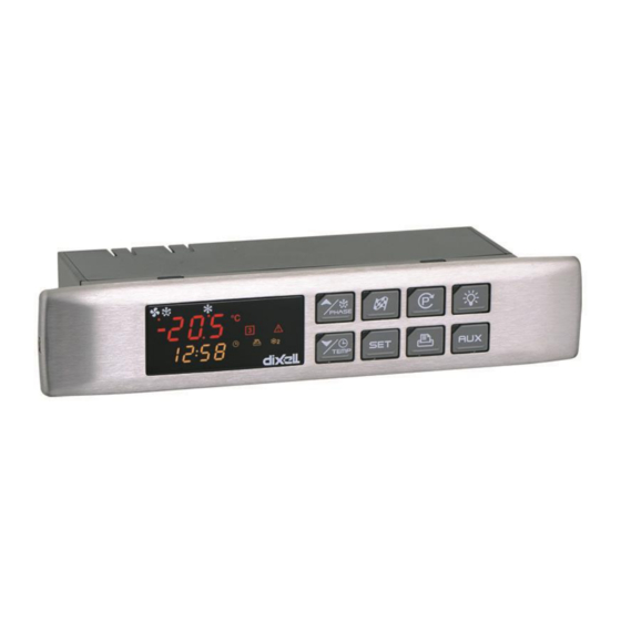
Page 3: Frontal Panel
7. FRONTAL PANEL 8. QUICK START 8.1 DISPLAY The upper display shows the temperature of the room probe. The lower display shows the temperature of the inserts probe or the count down timer. To pass to the one insert probe to the another one use the DOWN key. DISPLAY ... -
Page 4: How To Select A Cycle
8.2 KEYBOARD IN STAND-BY HOW TO SELECT A CYCLE: Push and release the (3) key till the desired cycle is selected. HOW TO START A CYCLE: Push and release the START/STOP button (2). Il The correspondent yellow LED is switched on.. HOW TO TEMPORARILY STOP THE RUNNING CYCLE. - Page 5 HOW DISPLAY / MODIFY THE SET POINT OF THE HOLDING PHASE DISPLAY: push release the SET key (6), the holding point selected cycle is displayed for 5 sec. this example holding set point of the TO MODIFY: while the set cycle 1 is modified.
- Page 6 PH1= phase 1 PHASE DISPLAY: pushing the UP key PH2= phase 2 the running phase is displayed. PH3= phase 3 DISPLAY REGULATION SET POINTS By pushing the SET key the following information are displayed in sequenze: - rSI = Room set point - iSI = Stop phase set point, referred to the insert probe - Back to the room temperature.
-
Page 7: Parameters
8.5 OTHER KEYS LIGHT (4): push the LIGHT (4) key to switch the light on and off. The status of the light is monitored by the yellow LED upper the key. AUX (8): push the AUX (8) key to switch the ausiliary on and off. The status of the auxiliary relay is monitored by the yellow LED upper the key. - Page 8 8.8 MEANING OF THE LEDS A series of light points on the front panels is used to monitor the loads controlled by the instrument. Each LED function is described in the following table. MODE ACTION Compressor enabled Programming Phase (flashing with LED Flashing Anti-short cycle delay enabled Fan enabled...
- Page 9 10. PARAMETERS REGULATION Hy Intervention differential for set point: (0.1 to 12.0 res. 0.1°C or 1°F) always positive. Compressor cut- IN is SET+HY. Compressor cut-OUT is when the temperature reaches the set point. AC Anti-short cycle delay: (0 to 30 min) minimum interval between the compressor stop and the following restart.
- Page 10 rrd Regulation restart with door open alarm: Y=count down and regualtion restart when door open alarm is signalled; n=compressor and fans stay according to the odC parameter when door open alarm is signalled. d2F Second digital input configuration (26-27): (EAL; bAL) EAL=external alarm; bAL=serious alarm, regulation is stopped.;...
- Page 11 HEATING (OSH<0): second compressor cut IN is OSS-OAH. Second compressor cut out is when the temperature OSS. OSi Probe selection for the second compressor: rP=thermostat probe; EP=evaporator probe; tiM=cycle count down; i1P=insert probe 1; i2P=insert probe 2; i3P=insert probe 3. DEFROST tdF Defrost type (not present in the XB350C): rE=electrical heater;...
-
Page 12: How A Cycle Is Done
tP3 Duration of third phase of the last cycle (read only). OTHER Adr Address for RS485: 1 to 247. bUt Buzzer activation at the end of the cycle: (0 to 60 sec; with 0 the buzzer is on till any key will be pushed). - Page 13 11.3 EXAMPLE OF A BLAST CHILLER CYCLE The following drawing explains how a Blast Chiller cycle can be done. Temper. FIRST PHASE: 2 PHASE 3 PHASE °C HARD CHILL SOFT CHILL FREEZING CYCLE Time Insert probe Room Probe 11.3.1 First phase: “Hard chill”. It is normally used to fast chill hot foods.
-
Page 14: Installation And Mounting
NOTE1: with dbH = yES a defrost is done before the holding phase. NOTE2: If the end cycle temperature iS3 is not reached in the maximum time Pd1+Pd2+Pd3 the instrument keep on working, but the alarm message “OCF” is given. 12. -
Page 15: Xb07Pr - Printer (Optional)
13. XB07PR - PRINTER (OPTIONAL) The XB570L is designed to work with the XB07PR. The XB07PR kit is composed by: Printer Power adapter Connecting cables 13.1 PRINTER DIMENSIONS 1592006207 XB570L GB r1.1 23.03.2015 XB570L 13/20... -
Page 16: Electrical Connections
13.2 PRINTER MOUNTING SCREW FIXING PANEL CUT OUT 13.3 CONNECTION TO THE XB570L – XB07PR 14. ELECTRICAL CONNECTIONS The instruments are provided with screw terminal block to connect cables with a cross section up to 2.5mm for the digital and analogue inputs. Relays and power supply have a Faston connection (6.3mm). Heat- resistant cables have to be used. -
Page 17: Ttl Serial Line
15. TTL SERIAL LINE The TTL connector allows, by means of the external module TTL/RS485, to connect the unit to a network line ModBUS-RTU compatible as the dIXEL monitoring system. The same TTL connector is used to upload and download the parameter list of the “HOT KEY”. 16. -
Page 18: Technical Data
18. TECHNICAL DATA Housing: self extinguishing ABS Case: frontal 185x38 mm; depth 70mm Mounting: panel mounting in a 150x31mm panel cut-out Frontal protection: IP65 Connections: screw terminal block ≤ 2.5mm wiring Power supply: 230Vac, ±10% Power absorption: 5VA max Display: dual display Inputs: 5 PTC or NTC probes Relay outputs: Compressor: relay SPST 20(8)A or 8(3) A, 250Vac... -
Page 19: Standard Values Of The Parameters
Cy4: direct fast freezing without holding CyS = tEP iS2=-18°C (0°F) Pd3 = OFF dbC = no rS2=-30°C (-22°F) dbH = no iS1 =-18°C (0°F) Pd2 =OFF HdS = OFF rS1=-30°C (-22°F) iS3=-18°C (0°F) Pd1 = 4.0 rS3=-30°C (-22°F) 20. STANDARD VALUES OF THE PARAMETERS. Lab Description Values Level... - Page 20 Lab Description Values Level FSt Fan stop temperature AFH Differential for the stop temperature and for the alarm Fnd Fan delay after defrost ALU MAXIMUM temperature alarm ALL Minimum temperature alarm ALd Temperature alarm delay EdA Alarm delay after defrost tbA Silencing alarm relay tCy Duration of last cycle - - -...
Need help?
Do you have a question about the Dixell XB Series and is the answer not in the manual?
Questions and answers