
Related Manuals for Emerson Liebert DM Chilled Water Series


Summary of Contents for Emerson Liebert DM Chilled Water Series
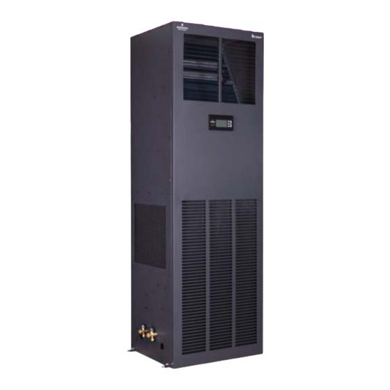
- Page 1 Precision Cooling For Business-Critical Continuity ™ Liebert DM Chilled Water Series ® User Manual...
- Page 2 Version: V1.0 Revision date: Nov. 03, 2012 ROM: 31012828 Emerson Network Power provides customers with technical support. Users may contact the nearest Emerson local sales office or service center. Copyright © 2010 by Emerson Network Power Co., Ltd. All rights reserved. The contents in this document are subject to change without notice.
-
Page 4: Table Of Contents
Contents Chapter 1 Overview ................................1 1.1 Model description ..................................1 1.2 Product introduction .................................1 1.3 Key parts ....................................1 1.4 Options .....................................2 1.4.1 Remote monitor ................................2 1.4.2 Energy-saving card ...............................2 1.5 Environmental requirement ..............................2 1.5.1 Operating environment ..............................2 1.5.2 Storage environment ..............................2 Chapter 2 Mechanical Installation ............................ - Page 5 5.4.1 Function description ..............................21 5.4.2 Operation example ..............................22 5.5 Control interface ..................................22 5.5.1 Shutdown interface ..............................22 5.5.2 Startup interface ................................. 22 5.5.3 Normal interface................................. 23 5.5.4 Password interface ..............................23 5.6 Menu structure..................................23 5.6.1 Main menu ................................. 23 5.6.2 Alarm menu................................
-
Page 6: Chapter 1 Overview
Chapter 1 Overview Chapter 1 Overview This chapter mainly introduces the model description, product profile, main parts, optional parts and environment requirement of Liebert_DM chilled water series cooling unit. 1.1 Model description The model description of Liebert_DM chilled water series cooling unit is as shown in Fig. 1-1 DM H 09 U M H 2 Version Cooling System . -
Page 7: Options
System for Communication Stations, Part III: Protocol for Front-end Intelligent Equipment. It realizes the communication with the host computer through the RS485 port and is controlled by the host software. For details about the monitoring software of Emerson, SiteMonitor, please refer to Appendix IV Introduction to SiteMonitor Monitoring Software. -
Page 8: Chapter 2 Mechanical Installation
: Pipeline provided by the manufacturer. : Pipeline laid onsite (by the technical staff) 3.*: These components are not provided by Emerson Network Power Co., Ltd, but they are recommended to be used for the normal operation of the system and maintenance. -
Page 9: Mechanical Parameters
Chapter 2 Mechanical Installation 2.3.2 Mechanical parameters Dimensions (mm) For the mechanical parameters of the unit, please refer to Fig.2-2 and Table 2-1. DMH09 unit DMH12 unit DMH17 unit DMH25 unit Fig.2-2 Outline dimensions of the units (unit: mm) User Manual of Liebert_DM Chilled Water Series Cooling Unit... - Page 10 Chapter 2 Mechanical Installation Table 2-1 Outline dimensions and weights of the units Product model Size (W×D×H) (mm) Net Weight (kg) ≤90 DMH09 510×386×1740 ≤127 DMH12 608×575×1900 ≤169 DMH17 1102×386×1740 ≤210 DMH25 1202×575×1900 Base cutting position and dimensions The base cutting position and dimensions are as shown in Fig.2-3. Bac k of the unit Bac k of the unit Chilled w ater outlet...
- Page 11 Chapter 2 Mechanical Installation Bac k of the unit Bac k of the unit Chilled w ater outlet Chilled w ater outlet Right s ide Right s ide Lef t s ide of Lef t s ide of Chilled w ater inlet of the unit of the unit the unit...
-
Page 12: Unit Installation
Chapter 2 Mechanical Installation F ro n t o f t h e u n it F ro n t o f t h e u n it B a c k o f t h e u n it B a c k o f t h e u n it C h ille d wa t e r o u t le t C h ille d wa t e r o u t le t... -
Page 13: Installation Space Requirement
Chapter 2 Mechanical Installation 3. All the doors and windows shall be air-tight, and the gaps shall be as small as possible. 2.4.2 Installation space requirement Note The DMH chilled water series cooling unit will produce condensed water. If there exists any water leakage, the adjacent precision equipment may be damaged. - Page 14 Chapter 2 Mechanical Installation 4 个 机 组 安 装 孔 4 个 机 组 安 装 孔 4 unit mounting holes 4 unit mounting holes 橡 胶 垫 ( 8 m m ~ 1 0 m m 厚 ) 橡...
- Page 15 Chapter 2 Mechanical Installation Rubber gasket Rubber gasket Rubber gasket 橡 胶 垫 ( 8 m m ~ 1 0 m m 厚 ) 橡 胶 垫 ( 8 m m ~ 1 0 m m 厚 ) (8mm~10mm) thick (8mm~10mm) thick (8mm~10mm) thick 4 unit mounting...
-
Page 16: Installation Of Unit Pipes
Chapter 2 Mechanical Installation 2.5 Installation of unit pipes The pipes to be connected include: 1. Drainage pipe of the unit: 2. Inlet and outlet pipes of chilled water. Connection of the drainage pipe The external diameter of the condensed water drainage pipe of the unit heat exchanger is 19mm. The condensed water drainage pipe is fixed to the right side of the unit base. -
Page 17: Items For Inspection
Chapter 2 Mechanical Installation 冷冻水进水管 冷冻水进水管 Chilled water inlet pipe Chilled water inlet pipe 冷冻水出水管 冷冻水出水管 Chilled water outlet pipe Chilled water outlet pipe Fig.2-7 Schematic diagram for connection of chilled water pipeTable2-2 External diameter and specifications for chilled water inlet and outlet pipes External diameter for chilled water inlet Specifications for threaded joint of chilled water... -
Page 18: Chapter 3 Electric Installation
Chapter 3 Electric Installation Chapter 3 Electric Installation This chapter introduces the electric installation of the Liebert_DM chilled water series cooling unit, including the task description, precautions, unit wiring and items for inspection. 3.1 Task description The wires to be connected onsite include: 1. -
Page 19: Connection Of Control Cable
Chapter 3 Electric Installation Note 1. Only the copper wire can be used, all the wires shall be firmly connected. 2. Ensure that the power supply voltage is equal to the rated voltage on the equipment nameplate. 3. Install a disconnecting switch before the unit power input, so that the power supply can be easily disconnected for equipment maintenance. -
Page 20: Connection Of Monitoring Cable
LCD will display the corresponding alarm contents. If computer with Emerson monitoring software is connected, the alarm will also be displayed on the computer. -
Page 21: Connection Of Energy-Saving Card
The simultaneous monitoring of several Liebert_DM chilled water series cooling units can be realized through the RS485 bus. Fig.3-7 is the schematic diagram for the networking of two Liebert_DM chilled water series cooling units monitored simultaneously through the RS485 bus, taking Emerson SiteMonitor software as the example. PC 后台 ( 安装... - Page 22 Chapter 3 Electric Installation COMM COMM 前盖 前盖 Front cover Front cover 拨码开关 拨码开关 Toggle switch Toggle switch 接口 接口 Port Port DME07MC1A2 DME07MC1A2 前视图 前视图 底视图 底视图 The energy-saving card adopts 4-core shielded cable for connection, and the Fig.3-8 Energy-saving card recommended cable size shall be no less than 20AWG (0.52mm ) .The reliable grounding of the shielded cable and the energy-saving card shall be ensured to enhance the immunity capacity.
-
Page 23: Items For Inspection
Chapter 3 Electric Installation 9. Use screws or the slot on the enclosure of the energy-saving card to fix the energy-saving card to the place with large thermal load in the room. 10. Enter the “sleep mode” menu to check if the temperature of the energy-saving card is normal. Fig.3-10 and Fig.3-11 are the connection schematic diagrams of single energy-saving card and several energy-saving cards respectively. -
Page 24: Chapter 4 System Test
Note The cooling unit has high voltage inside. Please cut off the power supply to the equipment before the test and operate under the guidance of the professional maintenance personnel of Emerson or other trained and qualified maintenance personnel. Cooling function commissioning Adjust the temperature setting value according to 5.6.3 setting point, so that it is 5º... -
Page 25: Chapter 5 Microprocessor
Chapter 5 Microprocessor Chapter 5 Microprocessor This chapter introduces the features, appearance, LCD, control keys, control interface and menu structure of the microprocessor of Liebert__DM cooling unit. Note Because the Liebert_DM Air cooling and chilled water series units share the same model of microprocessor, the contents related to the compressor control are applicable to the Air cooling series unit only. -
Page 26: Display
Chapter 5 Microprocessor 5.3 Display The LCD adopts Chinese menu and blue backlight. When the system is in normal operation, the LCD will display the indoor temperature and humidity (users may select whether to display humidity or not. For the setting method, please refer to 5.6.5 system setting), equipment output status (cooling, heating, dehumidification, humidification), unit property (single unit, master unit, slave unit), unit running status (running, standby, locked), alarm message and current time, as shown in Fig.5-2. -
Page 27: Operation Example
Chapter 5 Microprocessor 5.4.2 Operation example Example 1: Enter the password and enter the main menu After the system starts up, you can enter the main menu on the normal interface through the following operations: 1. Press ENTER and enter the password interface. 2. -
Page 28: Normal Interface
Chapter 5 Microprocessor Starting Fig.5-5 Startup interface 5.5.3 Normal interface After startup, when 10s (default setting) of hot startup delay is passed or ENTER key is pressed, the normal interface will be displayed, as shown in Fig.5-6. The normal interface displays the current temperature, humidity, equipment running status (cooling, heating, dehumidification, humidification), unit property (single unit, master, slave), unit running status (running, standby, locked), alarm message and the current date and time. -
Page 29: Alarm Menu
Chapter 5 Microprocessor operation of parameter setting, please refer to 5.4.2 Operation example. The setting range of all the settable parameters is shown in appendix III List of parameters. Alarm Menu Help Menu Set Points System Status System Menu Fig.5-8 Main menu interface The menu items in the main menu interface are as shown in Table 5-3. - Page 30 Chapter 5 Microprocessor History: History: Hi Temp Hi Temp 2009/01/11 00:00 2009/01/11 00:00 2009/01/11 01:22 Not Ended Yet Fig.5-11 Alarm history menu Note 1. When several alarms occur, press UP or DOWN key, the relevant alarm history information will be scrolled up or down.
- Page 31 Chapter 5 Microprocessor The alarm output items can be set as enabled, suspended or disabled. The alarm output logic is as shown in Table 5-4. Table 5-4 Alarm output logic Set value Alarm history record Alarm status record Alarm sound Alarm prompt Enabled Available...
-
Page 32: Setting Point
Chapter 5 Microprocessor 5.6.3 Setting point You can enter the setting point menu from the main menu interface, as shown in Fig.5-17. The setting point can be saved permanently. For the parameter setting range, please refer to appendix III list of parameters. -
Page 33: System Menu
Chapter 5 Microprocessor Running time The running time menu is as shown in Fig.5-22.You can inquire the running time of the equipment in this menu. 800h 200h Cool 200h Heat 200h Fig.5-22 Running time menu 5.6.5 System menu You can enter the system menu from the main menu interface, as shown in Fig.5-23. Setup System Change Password Select Options... - Page 34 Chapter 5 Microprocessor 180s 180s UnitStart Cp MinOff 180s Main Fan LP Switch Cp Start Cp MinOn 180s Fig.5-27 Delay time submenu Optional functions The optional function setting can be saved permanently. The optional function menu interface is as shown in Fig.5-28. For the parameter setting range, please refer to appendix III list of parameters.
- Page 35 Chapter 5 Microprocessor Note In the master/slave mode, one unit must be set as the master. If the two units are set as slave, neither of the two units can operate normally. Sensor calibration The sensor calibration menu allows the technician to calibrate the temperature or humidity sensor with the reference instrument (precision: 0.1º...
-
Page 36: Help Menu
Supplier Info Product Info Operation Help Fig.5-37 General information interface 1. The manufacturer information interface is as shown in Fig.5-38. EMERSON NETWORK POWER Co., Ltd Fig.5-38 Manufacturer information 2. The product information interface is as shown in Fig.5-39. Fig.5-39 Product information 3. - Page 37 Chapter 5 Microprocessor Service Record 3/10 2009/01/11 11:45 Fig.5-41 Maintenance record User Manual of Liebert_DM Chilled Water Series Cooling Unit...
-
Page 38: Chapter 6 System Maintenance
Chapter 6 System Maintenance Chapter 6 System Maintenance This chapter describes the system maintenance of the Liebert_DM chilled water series cooling unit, including the electric inspection, unit maintenance and maintenance checklist. Note 1. During the equipment maintenance, the circuit breaker shall be disconnected, and the equipment power supply shall be cut off, unless power supply is needed for the commissioning. -
Page 39: Fan
Chapter 6 System Maintenance Fig.6-1 Take out filter 6.2.2 Fan The monthly inspection of the fan components includes the motor operating status, fan impeller status, fixing of the fan components and the fit clearance between the fan and impeller. The operating status of the motor bearing and fan blades shall be checked monthly. If any damaged blade is found, the fan impeller shall be replaced in time. - Page 40 Chapter 6 System Maintenance 执行器 执行器 Actuator Actuator 连接件 连接件 Connector Connector 阀体 阀体 Valve body Valve body Fig.6-2 Water flow regulating valve Adjusting method The water flow regulating valve will automatically adjust the opening of the valve according to the cooling demand, so as to ensure that the temperature and humidity within the air conditioning room are controlled within the precision range.
-
Page 41: Maintenance Checklist
Chapter 6 System Maintenance 6.3 Maintenance checklist Note To ensure the normal operation of the equipment, routine maintenance and inspection shall be carried out regularly. Table 6-1 Maintenance checklist Liebert_DM cooling unit Date Maintenance personnel: Equipment model: Number on the unit body: Maintain or Type Objects for maintenance... -
Page 42: Chapter 7 Failure Diagnosis And Troubleshooting
Chapter 7 Failure Diagnosis and Troubleshooting Chapter 7 Failure Diagnosis and Troubleshooting This chapter introduces the failure diagnosis and troubleshooting of the Liebert_DM chilled water series cooling unit. For the failure diagnosis and troubleshooting measures, please refer to Table 7-1. Table 7-1 Failure Diagnosis and Troubleshooting Failure symptom Potential causes... -
Page 44: Appendix 1 Menu Structure Diagram
Appendix 2 Menu Structure Diagram Appendix 1 Menu Structure Diagram 主菜单 主菜单 Main menu Main menu 报警菜单 报警菜单 设定点 设定点 系统状态 系统状态 系统菜单 系统菜单 帮助菜单 帮助菜单 Setting point Setting point System status System status Help menu Help menu Alarm menu Alarm menu System menu System menu... -
Page 45: Appendix 2 List Of Parameters
Appendix 3 List of Parameters Appendix 2 List of Parameters Setting range menu Parameter name Default value High temperature The larger of (the temperature setting 30º C alarm points +5º C, 28º C) ~45º C Low temperature 5º C~the smaller of ( the temperature 18º... - Page 46 Appendix III List of Parameters menu Parameter name Default value Setting range Unit status Single unit Single unit, master Optional function _ Switching mode Master/slave Master/slave, polling mater/slave Polling cycle 1 day 1 day to 7 days Polling time 12: 00 0: 00~23: 00 Temperature 0.0º...
-
Page 47: Appendix 3 Introduction To Sitemonitor Software
Appendix 4 Introduction to SiteMonitor Software Appendix 3 Introduction to SiteMonitor Software SiteMonitor is the equipment monitoring software developed by Emerson. It can monitor the UPS, cooling units (CM+, Liebert_DM, Deluxe) and LTS series static transfer system (STS) developed by Emerson, control and handle various environment parameter values (such as temperature, humidity, smoke detector, flooding, infrared signal) through the equipment room signal adaptor and other relevant options. -
Page 48: Appendix 4 Symbol Table For Toxic/Hazardous Substances And Elements
Appendix 4 Symbol Table for Toxic/Hazardous Substances and Elements Note 1. SiteMonitor supports and works together with safe shutdown software to protect the computer data. For detailed information, please refer to User Manual for Safe Shutdown Software (Windows) and User Manual for Network Safe Shutdown Software (UNIX &... - Page 49 It means the content of this hazardous substance in at least one homogeneous material of this part is above the limit regulated in SJ/T-11363 –006; Emerson Network Power Co., Ltd. has always been devoted to designing and manufacturing environment friendly products. We will try to reduce and eliminate the toxic/hazardous substances in the products through continuous research. The following parts or the toxic/hazardous substances do not have reliable replacement or mature solutions due to the limitation of current technical level.
- Page 50 Emerson, Business-Critical Continuity and Emerson Network Power are trademarks of Emerson Electric Co. or one of its affi liated companies. ©2013 Emerson Electric Co.
Need help?
Do you have a question about the Liebert DM Chilled Water Series and is the answer not in the manual?
Questions and answers