Advertisement
Quick Links
INSTALLATION AND OPERATION MANUAL
FVT/FVR15M2
VIDEO WITH RETURN DATA
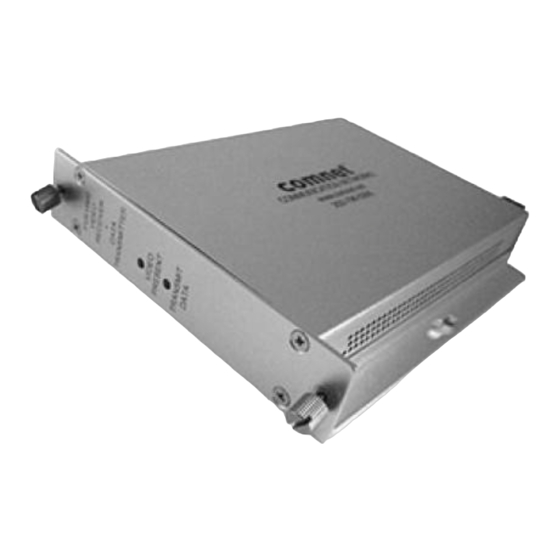
The ComNet™ FVT/FVR15M2 series video and data transceiver supports the
simultaneous transmission of video and return data over two multimode
optical fibers. The module is universally compatible with all major CCTV camera
manufacturers and supports RS232 and RS422 data interfaces and all major data
protocols. Plug-and-play design ensures ease of installation and no electrical or
optical adjustments are ever required.
Each transceiver incorporates a bi-color (Red/Green) indicating LED for monitoring
proper system operation. See Figure 6 on Page 3 for LED Indicator explanations.
The FVT/FVR15M2 may be directly plugged into the ComNet Rack (Part C1) or may be
either wall-mounted, rack-mounted, or DIN-rail mounted by the addition of ComNet
model DINBKT1 adaptor plate. See Figure A on Page 4 for mounting instructions.
See Figures 1 – 6 for complete installation details.
INS_FVTFVR15M2_REV–
09/23/11
PAGE 1
Advertisement

Related Manuals for Comnet ComNet FVT15M2


Summary of Contents for Comnet ComNet FVT15M2
- Page 1 Each transceiver incorporates a bi-color (Red/Green) indicating LED for monitoring proper system operation. See Figure 6 on Page 3 for LED Indicator explanations. The FVT/FVR15M2 may be directly plugged into the ComNet Rack (Part C1) or may be either wall-mounted, rack-mounted, or DIN-rail mounted by the addition of ComNet model DINBKT1 adaptor plate.
- Page 2 INSTALLATION AND OPERATION MANUAL FVT/FVR15M2 FIGURE 1 – FVT/FVR15M2 MULTIMODE OR SINGLE MODE OPTICAL FIBER BLACK BLACK WITH WHITE STRIPE/RED Power Supply: Surface Mount: 8–15 VDC @ 250mA Rack Mount: From Rack FIGURE 2 – FVT15M2 TRANSMITTER FIGURE 3 – FVR15M2 RECEIVER FRONT PANEL REAR PANEL FRONT PANEL...
- Page 3 INSTALLATION AND OPERATION MANUAL FVT/FVR15M2 FIGURE 4 – DATA CONNECTIONS TRANSMITTER RECEIVER RS-232/RS-422 RS-232/RS-422 (-) DATA IN RS-232 OUT RS-422 (+) DATA IN (+) DATA OUT RS-232 RS-422 (-) DATA OUT Manchester/Bi-phase Manchester/Bi-phase (-) DATA IN Manchester/ Bi-phase (+) DATA OUT Manchester/ (+) DATA IN Bi-phase...
- Page 4 8 TURNbERRy PARk ROAD | GILDERSOME | MORLEy | LEEDS, Uk LS27 7LE T: +44 (0)113 307 6400 | F: +44 (0)113 253 7462 | INFO-EUROPE@cOMNET.NET INS_FVTFVR15M2_REV– 09/23/11 © 2011 Communications Networks Corporation. All Rights Reserved. “ComNet” and the “ComNet Logo” are registered trademarks of Communication Networks, LLC. PAGE 4...
Need help?
Do you have a question about the ComNet FVT15M2 and is the answer not in the manual?
Questions and answers